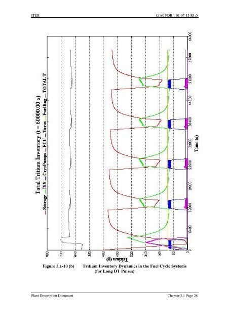
ITER G A0 FDR 1 01-07-13 R1.0Figure <strong>3.1</strong>-10 (b)<strong>Tritium</strong> Inventory Dynamics in the Fuel Cycle Systems(for Long DT Pulses)<strong>Plant</strong> Description Document Chapter <strong>3.1</strong> Page 26
ITER G A0 FDR 1 01-07-13 R1.0<strong>3.1</strong>.2.4 <strong>Tritium</strong> Confinement <strong>and</strong> <strong>Detritiation</strong> SubsystemsHVACBecause of their functional requirements during off-normal events in the tokamak, tritium,hot cell <strong>and</strong> radwaste buildings, the HVAC systems are safety classified systems thereforethere are 2 emergency room isolation dampers (high leak tightness butterfly valves) in seriesbacked up by emergency power <strong>and</strong>/or emergency compressed gas (N 2 ). However, allHVAC equipment such as blowers, heating <strong>and</strong> cooling coils, pre-filters <strong>and</strong> HEPA (highefficiency particulate) filters, emergency isolation dampers, <strong>and</strong> fire isolation dampers areindustrial items, <strong>and</strong> no specific R&D has been required for their use in ITER.Atmosphere <strong>Detritiation</strong> SystemsAs described in <strong>3.1</strong>.1.2, different atmosphere detritiation systems are employed to meet theconfinement <strong>and</strong> detritiation requirements at different operation states of the tokamak,tritium, hot cell <strong>and</strong> radwaste buildings. The process configurations of these atmospheredetritiation systems are different, based on the confinement strategy <strong>and</strong> safety requirements(off-normal event scenarios).Figure <strong>3.1</strong>-11 shows a conceptual process flow diagram of the st<strong>and</strong>by atmospheredetritiation system, which is a typical safety classified atmosphere detritiation systemsimilar to the normal vent detritiation system, st<strong>and</strong>by vent detritiation system, hot cellatmosphere detritiation system <strong>and</strong> the hot cell vent detritiation system. The st<strong>and</strong>byatmosphere detritiation system is designed to process various tritiated source gases containinghigh levels of elemental tritium, tritiated hydrocarbons, <strong>and</strong> saturated moisture. The processconfiguration is characterised by the three loops described below.a) Recombiner loop composed of inlet filter (F-1), inlet blower battery (BL1-A/B/C: 50%capacity/each blower; one blower is redundant), two stage recombiners (Rec-L, Rec-H),two stage recuperative heat exchangers (HX-1, HX-2), one stage electric heater (EH-1),one stage condenser (CX-1), <strong>and</strong> one-stage molecular sieve dryer bed battery (DX-A/B/C). Elemental tritium included in the source gas/air is catalytically converted(conversion factor > 10 4 ) into tritiated water molecules by the first stage recombiner(operating temperature 150°C), <strong>and</strong> tritiated organic species are oxidised (conversionfactor > 10 3 ) to tritiated water molecules <strong>and</strong> CO 2 by the second stage recombiner(operating temperature 500°C). The converted tritiated water molecules are adsorbed bythe molecular sieve dryer bed. Thus, overall tritium permeation through vessel walls <strong>and</strong>pipe lines in the recombiner loop can be minimised by the two-stage recombinerconfiguration. This configuration was selected as an essential design feature to processtritiated source gases containing elemental tritium <strong>and</strong> organic tritium. The glove boxatmosphere detritiation system process uses only a one stage recombiner (operatingtemperature 150°C) because the expected tritiated species in the glove box atmosphereare elemental tritium <strong>and</strong> tritiated moisture (HTO).<strong>Plant</strong> Description Document Chapter <strong>3.1</strong> Page 27