DMX 3-in-1 splitter/isolator/repeater - Chameleon
DMX 3-in-1 splitter/isolator/repeater - Chameleon
DMX 3-in-1 splitter/isolator/repeater - Chameleon

You also want an ePaper? Increase the reach of your titles
YUMPU automatically turns print PDFs into web optimized ePapers that Google loves.
GENERALINTEREST<br />
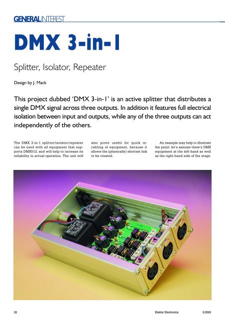
<strong>DMX</strong> 3-<strong>in</strong>-1<br />
Splitter, Isolator, Repeater<br />
Design by J. Mack<br />
This project dubbed ‘<strong>DMX</strong> 3-<strong>in</strong>-1’ is an active <strong>splitter</strong> that distributes a<br />
s<strong>in</strong>gle <strong>DMX</strong> signal across three outputs. In addition it features full electrical<br />
isolation between <strong>in</strong>put and outputs, while any of the three outputs can act<br />
<strong>in</strong>dependently of the others.<br />
The <strong>DMX</strong> 3-<strong>in</strong>-1 <strong>splitter</strong>/<strong>isolator</strong>/<strong>repeater</strong><br />
can be used with all equipment that supports<br />
<strong>DMX</strong>512, and will help to <strong>in</strong>crease its<br />
reliability <strong>in</strong> actual operation. The unit will<br />
also prove useful for quick recabl<strong>in</strong>g<br />
of equipment, because it<br />
allows the (physically) shortest l<strong>in</strong>k<br />
to be created.<br />
An example may help to illustrate<br />
the po<strong>in</strong>t: let’s assume there’s <strong>DMX</strong><br />
equipment at the left-hand as well<br />
as the right-hand side of the stage.<br />
20<br />
Elektor Electronics 5/2003
GENERALINTEREST<br />
+5V-1<br />
C5<br />
2<br />
3<br />
IC9<br />
8<br />
7<br />
6<br />
4k7<br />
R3<br />
1<br />
2<br />
3<br />
4<br />
IC6 8<br />
R<br />
D<br />
7<br />
6<br />
100n<br />
GND1<br />
K3<br />
TR1<br />
6V<br />
B1<br />
C2<br />
IC2<br />
7805<br />
+5V-1<br />
C8<br />
+5V<br />
5<br />
6N137<br />
5<br />
LTC485<br />
B40C1000<br />
470µ<br />
16V<br />
GND1<br />
1µ<br />
16V<br />
K2<br />
120Ω<br />
R1<br />
6<br />
7<br />
C12<br />
100n<br />
IC5<br />
8<br />
1<br />
R 2<br />
3<br />
220Ω<br />
D 4<br />
5 LTC485<br />
R2<br />
+5V-2<br />
IC10<br />
2<br />
3<br />
+5V-3<br />
8<br />
7<br />
6<br />
5<br />
6N137<br />
4k7<br />
GND1<br />
R4<br />
GND2<br />
1<br />
2<br />
3<br />
4<br />
IC7 8<br />
R<br />
7<br />
6<br />
D<br />
5<br />
LTC485<br />
C6<br />
100n<br />
GND2<br />
K4<br />
F1<br />
100mA T<br />
K1<br />
230V<br />
2x 1VA5<br />
TR2<br />
6V<br />
6V<br />
B2<br />
B40C1000<br />
B3<br />
IC1<br />
7805<br />
C1<br />
470µ<br />
16V<br />
GND<br />
IC4<br />
7805<br />
C4<br />
+5V<br />
C9<br />
1µ<br />
16V<br />
+5V-3<br />
C10<br />
GND<br />
IC11<br />
2<br />
3<br />
8<br />
7<br />
6<br />
4k7<br />
R5<br />
1<br />
2<br />
3<br />
4<br />
IC8 8<br />
R<br />
D<br />
7<br />
6<br />
C7<br />
100n<br />
GND3<br />
K5<br />
2x 1VA5<br />
6V<br />
B40C1000<br />
B4<br />
470µ<br />
16V<br />
GND3<br />
IC3<br />
7805<br />
C3<br />
1µ<br />
16V<br />
+5V-2<br />
C11<br />
5<br />
6N137<br />
5<br />
LTC485<br />
B40C1000<br />
470µ<br />
16V<br />
1µ<br />
16V<br />
GND3<br />
GND2<br />
020117 - 11<br />
Figure 1. The circuit diagram of the <strong>DMX</strong> 3-<strong>in</strong>-1 comprises four electrically isolated subsections.<br />
Without the <strong>splitter</strong>, it would be<br />
awkward to feed one cable to one<br />
side only, then take it back all the<br />
way to the orig<strong>in</strong>, then on to the<br />
other side, and then from equipment<br />
to equipment. Arguably, this is not<br />
the best solution to distribut<strong>in</strong>g<br />
<strong>DMX</strong> signals across equipment.<br />
The <strong>DMX</strong> <strong>splitter</strong> makes the<br />
cabl<strong>in</strong>g job much easier. Only one<br />
cable is required at each side,<br />
where it is used to <strong>in</strong>terconnect all<br />
equipment.<br />
Repetitia Placet<br />
A quick glance at the circuit diagram<br />
<strong>in</strong> Figure 1 shows that the <strong>DMX</strong> 3-<br />
<strong>in</strong>-1 consist of three identical sub-circuits.<br />
Resistor R1 at the <strong>in</strong>put of the<br />
circuit acts as a term<strong>in</strong>ator (‘term<strong>in</strong>at<strong>in</strong>g<br />
resistance’) for the <strong>DMX</strong> bus,<br />
which, as you may know, works <strong>in</strong><br />
compliance with well established<br />
RS485 standards. The <strong>DMX</strong> signal is<br />
first converted to TTL by level converter<br />
IC5. The LTC485 from L<strong>in</strong>ear<br />
Technology is an <strong>in</strong>terface component<br />
that translates RS485 signals<br />
<strong>in</strong>to TTL (receiver, R), and vice versa,<br />
TTL <strong>in</strong>to RS485 (driver, D). In this circuit<br />
the transmitter section of the<br />
chip has been disabled. The<br />
datasheets of this <strong>in</strong>terest<strong>in</strong>g chip<br />
may be found at<br />
www.l<strong>in</strong>ear-tech.com/pdf/485ff.pdf<br />
Beh<strong>in</strong>d IC5, the signal is split across<br />
three identical circuits. High-speed<br />
optocouplers type 6N137 guarantee<br />
electrical isolation. Resistor R2 limits<br />
the current through the LEDs <strong>in</strong>side<br />
the optocouplers. The optocouplers<br />
are enabled by means of a High level<br />
at p<strong>in</strong> 7. Pull-up resistors (R3, R4, R5)<br />
are required at their outputs which<br />
are of the open-collector (OC) variety.<br />
Next, the signal once aga<strong>in</strong> meets<br />
an LT485. This time, however, only<br />
the transmitter (D) is employed. A<br />
small difference may be noted with<br />
respect to IC5: Because of the <strong>in</strong>vert<strong>in</strong>g<br />
action of the optocouplers, the<br />
outputs of the LTC485’s are transposed<br />
to prevent unwanted <strong>in</strong>version.<br />
The tripled <strong>DMX</strong> signal leaves<br />
the circuit via connectors K3, K4 and<br />
K5. The electrical isolation that exist<br />
between the three outputs will<br />
prove <strong>in</strong>valuable when errors occur.<br />
An error on one <strong>DMX</strong> l<strong>in</strong>e will only cause one<br />
output to fail <strong>in</strong>stead of the complete unit —<br />
the other outputs will cont<strong>in</strong>ue to operate<br />
normally!<br />
The power supply is seen <strong>in</strong> the righthand<br />
section of the circuit diagram. Because<br />
we are deal<strong>in</strong>g with four electrically isolated<br />
sub-circuits <strong>in</strong> the <strong>DMX</strong>512 path, there is a<br />
requirement for four <strong>in</strong>dependently operat<strong>in</strong>g<br />
power supplies. Although this requirement<br />
could be fulfilled us<strong>in</strong>g a ma<strong>in</strong>s supply <strong>in</strong>corporat<strong>in</strong>g<br />
special DC/DC converters, the current<br />
consumption of the circuit is so low that<br />
two 1.5-VA transformers, each hav<strong>in</strong>g two<br />
secondary w<strong>in</strong>d<strong>in</strong>gs, are probably cheaper<br />
and less demand<strong>in</strong>g <strong>in</strong> respect of board<br />
space, albeit less elegant. Each of the four<br />
secondaries is followed by a small rectifier<br />
bridge feed<strong>in</strong>g a three-p<strong>in</strong> fixed voltage regulator<br />
type 7805.<br />
Construction<br />
The artwork for the pr<strong>in</strong>ted circuit board (Figure<br />
2) shows a dead conventional project<br />
when it comes to build<strong>in</strong>g it. Ready-made<br />
pr<strong>in</strong>ted circuit boards for the project may be<br />
obta<strong>in</strong>ed from The PCBShop (i.e., they are not<br />
available through Elektor’s Readers Services).<br />
Do not forget to fit all 4 (four) wire l<strong>in</strong>ks on the<br />
5/2003 Elektor Electronics 21
H2<br />
H1<br />
ELEKTOR<br />
(C)<br />
020117-1<br />
H3<br />
H4<br />
GENERALINTEREST<br />
K1<br />
F1 100mAT<br />
TR2<br />
TR1<br />
B4<br />
B3<br />
B1<br />
B2<br />
C3<br />
IC4<br />
C4<br />
IC2<br />
C2<br />
IC1<br />
C1<br />
IC3<br />
C11<br />
C10<br />
C8<br />
C9<br />
C12<br />
R2<br />
IC5<br />
R1<br />
T<br />
IC9 IC11 IC10<br />
R4<br />
C6<br />
R5<br />
R3<br />
- +<br />
020117-1<br />
IC6 IC8 IC7<br />
K5<br />
C7<br />
K2<br />
C5<br />
K4<br />
K3<br />
+<br />
-<br />
T<br />
+<br />
-<br />
T<br />
+<br />
-<br />
T<br />
board and be sure to mount all ICs<br />
with the correct orientation. IC sockets<br />
are recommended, but not obligatory.<br />
The enclosure that holds the <strong>DMX</strong><br />
3-<strong>in</strong>-1 must be ‘stage, bullet and foolproof’<br />
as well as electrically safe,<br />
comply<strong>in</strong>g with Class-2 electrical<br />
isolation requirements. In particular,<br />
the distance between ma<strong>in</strong>s-carry<strong>in</strong>g<br />
parts on the PCB and the metal<br />
case should be 6 mm m<strong>in</strong>imum. This<br />
rules out the use of 5-mm PCB spacers.<br />
The XLR chassis-mount sockets/plugs<br />
and the IEC appliance<br />
socket are best secured to the case<br />
with rivets.<br />
(020117-1)<br />
COMPONENTS LIST<br />
Resistors:<br />
R1 = 120Ω<br />
R2 = 220Ω<br />
R3,R4,R5 = 4kΩ7<br />
Capacitors:<br />
C1-C4 = 470µF 16V radial<br />
C5,C6,C7,C12 = 100nF<br />
C8-C11 = 1µF 16V radial<br />
(C) ELEKTOR<br />
020117-1<br />
Semiconductors:<br />
B1-B4 = B40C1000, round case<br />
(40V piv, 1A)<br />
IC1-IC4 = 7805<br />
IC5-IC8 = LTC485CN8 or<br />
SN75176BP<br />
IC9,IC19,IC11 = 6N137<br />
Figure 2. Copper track layout and component mount<strong>in</strong>g plan (board available from The<br />
PCBShop).<br />
Miscellaneous :<br />
F1 = fuse holder, PCB mount,<br />
with fuse 100mA(T) (slow)<br />
K1 = 2-way PCB term<strong>in</strong>al block,<br />
lead pitch 7.5mm<br />
K2-K5 = 3- way PCB term<strong>in</strong>al<br />
block, lead pitch 5mm<br />
Tr1,Tr2 = ma<strong>in</strong>s transformer, 2x6<br />
V secondaries, 1.5VA or 2 VA<br />
1 off IEC ma<strong>in</strong>s appliance socket<br />
3 off XLR socket (female), 3-way,<br />
chassis mount, 180 degrees<br />
1 off XLR plug (male), 3-way,<br />
chassis mount, 180 degrees<br />
PCB, available from The<br />
PCBShop<br />
22 Elektor Electronics 5/2003