Nivtec Assembly instructions 2009 - Chameleon
Nivtec Assembly instructions 2009 - Chameleon
Nivtec Assembly instructions 2009 - Chameleon

You also want an ePaper? Increase the reach of your titles
YUMPU automatically turns print PDFs into web optimized ePapers that Google loves.
nivtec-flexibel Bühnensysteme GmbH<br />
Walter-Freitag-Str. 31<br />
D-42899 Remscheid<br />
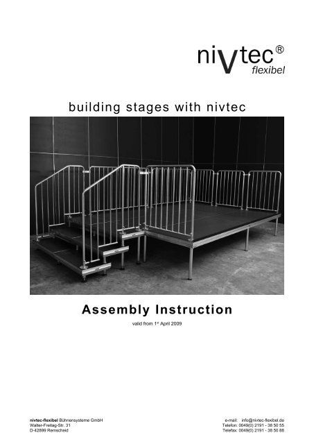
building stages with nivtec<br />
<strong>Assembly</strong> Instruction<br />
valid from 1 st April <strong>2009</strong><br />
e-mail: info@nivtec-flexibel.de<br />
Telefon: 0049(0) 2191 - 38 50 55<br />
Telefax: 0049(0) 2191 - 38 50 88
valid from 1 st April <strong>2009</strong> page 1 of 15<br />
<strong>Assembly</strong> Instruction nivtec Staging System<br />
This assembly instruction for a standard modular stage size 6 x 4 m and its extensions. It contains step by step <strong>instructions</strong><br />
how to assemble a safe and stable stage and how to attach additional nivtec system parts such as stairways, rails etc.<br />
Besides standard stages also specially shaped stages are possible. The assembly of these stages is, however, not<br />
executed according to the general <strong>instructions</strong> but is subject to an individual assembly instruction and structural analysis.<br />
In this case please contact us enabling us to either authorize your plans or to instruct our structural engineers to work out<br />
an individual measurement and strutting plan at fair local conditions.<br />
The selected legs should be appropriate for the local ground surface. Depending on the nature of the floor surface it is<br />
essentiel to use floor protectors, especially on slippery or sensible surfaces (concrete, tiles, parquet etc.).<br />
Stage constructions may only be set up on stable ground and have to be aligned horizontally. For constructions on rough<br />
grounds it is essentiel to use wooden underpinnings acc. to the standard values listed in DIN 4112, item 6.3.<br />
ill. 1: mounting of legs (bottom of platform)<br />
open<br />
leg support<br />
locked<br />
I. connection of legs and nivtec platform<br />
Fit the leg (see ill. 6 – 8) into the corner leg support at the bottom of the platform and tighten it by pulling the clamping<br />
lever (see ill. 1). For position and quantity of legs please see ill. 2. If the standard module is to be altered in depth and /<br />
or width please proceed according to the pattern shown.<br />
II. connection of platforms<br />
The assembly starts with the first platform on 4 legs at the rear right end.<br />
The tongue profiles are pointed to the rear resp. to the right side (see ill. 3).<br />
ill. 4: tongue and groove profiles<br />
To connect the system<br />
platforms the tongue profile<br />
is hooked into the<br />
groove profile (see ill. 4).<br />
For tightening the platform connection please move the handle bar of<br />
the locking mechanism at the bottom of the tongue profiles (see ill. 5).<br />
Immediately after a platform has been hooked to the previous one it is<br />
absolutely essential to securely lock this connection by moving the<br />
handle bar into position “locked” and to check the stability of the connection.<br />
Now the next platform can be mounted.<br />
ill. 2: stage module 6 x 4 m<br />
ill. 3: position of platforms<br />
tongue profile<br />
ill. 5: locking of platforms<br />
open locked<br />
1<br />
locked<br />
open
valid from 1 st April <strong>2009</strong> page 2 of 15<br />
ill. 6: nivtec-levelling leg<br />
with adj. spindle<br />
locknut<br />
III. height adjustment of stage<br />
Up to a stage height of 80 cm nivtec legs ø48,3 x 4 mm made of aluminium or steel may be used, for heights exceeding<br />
80 cm steel legs are essential.<br />
For height adjustment please turn the adjusting spindle (see ill. 6). Adjustments of 6 cm are possible. If you use legs with<br />
adj. spindle for stages exceeding 60 cm please tighten the locknut after finishing the fine adjustment.<br />
nivtec extension legs (see ill. 7) allow height adjustment from 40 to 60 cm, from 60 to 100 cm and from 80 to 140 cm in<br />
intervals of 5 cm. In order to adjust the height the inner and outer tubes of the leg are moved until the respective holes<br />
overlap. Then the leg height is fixed with the safety bolt clip. For fine adjustment please turn the adjusting spindle and<br />
tighten the locknut.<br />
Quick, easy and stepless adjustments can also be achieved by using nivtec legs with Layher scaffold spindle (see ill. 8).<br />
The following maximum spindle ways for leg raster 2 x 1 m are to be respected: 25 cm for spindle 60 cm, 40 cm for spindle<br />
80 cm. To achieve the required stage height adapter legs in appropriate sizes are to be used. (For spindle ways for leg<br />
raster 2 x 2 m please see our construction plans.)<br />
For <strong>instructions</strong> how to equip the various base constructions of stages with appropriate braces please see page 6. Warranty<br />
of stability is subject to exclusive use of original nivtec parts resp. to stage assembly according to nivtec <strong>instructions</strong> (for<br />
example when using Layher parts).<br />
ill. 9: assembly of stairway (hook on - stairway)<br />
1<br />
2<br />
3<br />
ill. 7: nivtec extension leg ill. 8: nivtec levelling leg<br />
with Layher scaffold spindle<br />
IV. assembly of nivtec stairway<br />
step leg<br />
support bolt ø39 mm<br />
hook on - stairway<br />
slip on nivtec<br />
adapter leg<br />
complete Layher<br />
scaffold spindle<br />
1. Equip the first step with 4 levelling<br />
legs 20 cm and 2 support bolts<br />
ø39 mm for the next step and<br />
tighten them.<br />
2. Equip the second step with<br />
nivtec step legs 20 cm at the front<br />
and 2 stage legs 40 cm at the rear<br />
and attach the support bolts. Repeat<br />
this for the next steps. The length of<br />
the rear legs is always increased by<br />
20 cm.<br />
3. Hook the tongue profile of the last<br />
step into the groove profile of the<br />
stage and lock the connection.<br />
4. For attachment of stairway at the<br />
tongue profile of a stage attached<br />
apater lath.
valid from 1 st April <strong>2009</strong> page 3 of 15<br />
push on - stairway<br />
Steps 1 and 2 of assembly of a push-on stairway are the same as for the hook-on stairway. Please mind the special size of<br />
the last step (depth 39 cm – with adapted leg support) necessary for achieving a uniform tread. Next please align stairway<br />
to stage at the position required.<br />
Connection of stairway and stage:<br />
solution 1 for groove stage profile: 1 gallery link 110 mm, Art.No. 401 10 0, 1 special link N-F, Art.No. 402 01 0<br />
solution 2 for groove stage profile: 2 special links N-F, Art.No. 402 01 0 (if there is no stage leg)<br />
solution for tongue stage profile: 2 gallery links 110 mm, Art.No. 401 10 0, if necessary add stage leg<br />
ill. 10: assembly of safety rails<br />
link<br />
V. fastening of safety rails<br />
adapter<br />
ill. 10a: support bolt ill. 10b: set screws<br />
1. Remove the blue caps.<br />
2. Screw in support bolt<br />
ø26 mm (see ill. 10a) and<br />
tighten it with spanner<br />
size 19.<br />
3. At places without a leg<br />
underneath please equip<br />
the leg support with a<br />
thread adapter (see ill. 10).<br />
4. Slip rails on support bolts.<br />
5. Tighten the set screws<br />
(see ill.10b).<br />
6. The rails are connected with<br />
links Art.No. 310 10 0 at the<br />
top range of the rail post.<br />
tighten screw
valid from 1 st April <strong>2009</strong> page 4 of 15<br />
ill. 11: connection of rails at corners<br />
1. Remove the blue caps of the stairway.<br />
metal clamp<br />
ill. 12: assembly of safety stairway rail<br />
first part<br />
middle part<br />
2. Screw in support bolt ø26 mm (see ill. 10a) and tighten it.<br />
VI. attachment of safety stairway rail<br />
Start the assembly of the safety rail at the rear<br />
of the stage. Next the side rails are attached.<br />
The side and the rear rail have to be connected<br />
with two corner links Art.No. 310 21 0 per<br />
corner.<br />
Fit the metal clamp around both rails posts and<br />
tighten the screw of the clamp.<br />
new execution since 01.04.<strong>2009</strong>:<br />
fit screw between rails posts, fit metal clamps<br />
around the posts and tighten the screw.<br />
3. Combine first, middle and final parts to form the stairway rail required. Depending on the size of the stairway the<br />
rail size can be adjusted by using single, double or triple middle parts.<br />
4. Slip the complete rail on the support bolts.<br />
new execution<br />
tighten screw<br />
metal clamp<br />
tighten screw<br />
5. Tighten the set screws. These screws have to be at the outside of the rail.<br />
6. hook-on stairway: connect final part of stairway rail and stage rail with safety rail link 150 mm, Art.No. 310 10 0,<br />
and tighten the screw.<br />
8. push-on stairway: connect final part of stairway rail and stage rail with safety rail link 110 mm, Art.No. 310 11 0,<br />
and tighten the screw.<br />
final part<br />
set screw<br />
(see ill. 10b)
valid from 1 st April <strong>2009</strong> page 5 of 15<br />
VII. safety rails with vertical bars<br />
For attachment of safety rails with vertical bars the same regulations are valid. Stairway rails are supplied<br />
as complete rails depending on the size of the stairway. The following drawings show examples of stages /<br />
galleries equipped with safety rails with vertical bars. Contrary to the method shown in illustration 14 with a rail<br />
85 cm per platform you may also use a rail 185 cm covering two platforms. It is absolutely necessary that rails<br />
are connected and secured with rail links resp. corner links. When attaching a stairway at the side of a stage<br />
the stage rails have to be adapted. Please take special care in closing gaps. In case of need please ask for<br />
further details.<br />
ill. 13 - example: rails at the back of stages and galleries<br />
1 safety rail with vertical bars 185 cm 2 rail link 150 mm 3 corner link<br />
Nr.: 303 03 0 Nr.: 310 10 0 Nr.: 310 21 0<br />
ill. 14 - example: rails at the side of stages and galleries<br />
1 safety rail with vertical bars 85 cm 2 stairway rail with vertical bars for 3-step stairway<br />
Nr.: 303 02 0 Nr.: 305 02 1<br />
1 rail link 110 mm 2 safety rail with vertical bars 85 cm 3 gallery link<br />
Nr.: 310 11 0 Nr.: 303 02 0 Nr.: 401 10 0
valid from 1 st April <strong>2009</strong> page 6 of 15<br />
VIII. bracing <strong>instructions</strong><br />
In order to always achieve maximum safety for the stage users we have modified our assembly <strong>instructions</strong> for building<br />
stages with various base constructions. The modifications have been made in observance of the latest safety regulations<br />
and considering the maximum load capacity of a stage. They also serve as protection of the material used and its<br />
durability. For details about the required bracing parts please see page 15.<br />
Base constructions with stage legs from height 80 cm are reinforced with diagonal braces at each corner and in intervals<br />
of two free bays at the outside. Braces are to be attached as follows:<br />
- at each stage corner<br />
- covering one bay at the sides with 2 m leg distance (see ill. 15)<br />
- covering one or two bays at the sides with 1 m leg distance (see ill. 17 or 16)<br />
- no more than two free bays in a row are allowed at any stage side<br />
ill. 15:<br />
ill. 16:<br />
ill. 17:<br />
Additional horizontal braces at the outside are only required when using extension legs at heights exceeding 120 cm – see<br />
drawing of stage module at the bottom of page 8.<br />
Base constructions for stage heights exceeding 140 cm up to 240 cm are to be equipped with diagonal and horizontal<br />
braces - see drawing of stage module on page 9.<br />
The same regulations apply to gallery constructions - see drawings of gallery modules on pages 11 - 14.<br />
Stage constructions of nivtec weight girder system in combination with Layher Metric Allround Scaffold System can be<br />
built up to a height of 300 cm - see drawings of stage module on page 10.<br />
The stage modules shown on the following pages are to be considered as review of the various possibilities to<br />
build different base constructions of the nivtec staging system in raster 2 x 1 m resp. 2 x 2 m. The assembly has<br />
to be executed exclusively according to our <strong>instructions</strong>. Please ask for the construction plan of the stage you<br />
are planning.
valid from 1 st April <strong>2009</strong> page 7 of 15<br />
IX. review of stage modules<br />
stage nivtec-flexibel, 6 x 4 m - in modular design – leg raster 2 x 1 m<br />
stage height: below 80 cm<br />
stage nivtec-flexibel, 6 x 4 m - in modular design – leg raster 2 x 1 m<br />
stage height: 80 cm
valid from 1 st April <strong>2009</strong> page 8 of 15<br />
IX. review of stage modules<br />
stage nivtec-flexibel, 6 x 4 m - in modular design – leg raster 2 x 1 m<br />
stage height: from 80 cm up to 140 cm<br />
stage height with extension legs: from 80 cm up to 120 cm<br />
stage nivtec-flexibel, 6 x 4 m - in modular design – leg raster 2 x 1 m<br />
stage height with extension legs: exceeding 120 cm up to 140 cm
valid from 1 st April <strong>2009</strong> page 9 of 15<br />
IX. review of stage modules<br />
stage nivtec-flexibel, 6 x 4 m - in modular design – leg raster 2 x 1 m<br />
stage height: exceeding 140 cm up to 240 cm
valid from 1 st April <strong>2009</strong> page 10 of 15<br />
IX. review of stage modules<br />
stage nivtec-flexibel, 6 x 6 m - in modular design – leg raster 2 x 2 m<br />
nivtec weight girder system in combination with Layher base construction<br />
stage height: 180 cm<br />
stage nivtec-flexibel, 6 x 6 m - in modular design – leg raster 2 x 2 m<br />
nivtec weight girder system in combination with Layher base construction<br />
stage height: 300 cm
valid from 1 st April <strong>2009</strong> page 11 of 15<br />
IX. review of stage modules<br />
seat gallery nivtec-flexibel in modular desgin<br />
gallery height: 140 cm tier height: 20 cm
valid from 1 st April <strong>2009</strong> page 12 of 15<br />
IX. review of stage modules<br />
seat gallery nivtec-flexibel in modular desgin<br />
gallery height: 240 cm tier height: 20 cm
valid from 1 st April <strong>2009</strong> page 13 of 15<br />
IX. review of stage modules<br />
seat gallery nivtec-flexibel in modular desgin<br />
gallery height: 120 cm tier height: 40 cm
valid from 1 st April <strong>2009</strong> page 14 of 15<br />
IX. review of stage modules<br />
seat gallery nivtec-flexibel in modular desgin<br />
gallery height: 240 cm tier height: 40 cm
valid from 1 st April <strong>2009</strong> page 15 of 15<br />
braces: steel tube 48,3 x 4 mm - diagonal<br />
swivel coupling<br />
Layher 48,3 mm<br />
swivel coupling<br />
Layher 48,3 mm<br />
reduction swivel coupling<br />
Plettac 48,3 / 38 mm<br />
for use with<br />
all legs at the top<br />
for use with extension legs<br />
at zero adjustement at the bottom<br />
braces: steel tube 48,3 x 4 mm - horizontal<br />
standard coupling<br />
Layher 48,3 mm<br />
for use on the inner tube of<br />
extensions legs at the bottom<br />
for use with<br />
all legs<br />
except:<br />
reduction swivel coupling<br />
Plettac 48,3 / 38 mm<br />
for use with other<br />
legs at the bottom<br />
for use on the inner tube<br />
of extension legs