Newsletter47 - Winter 2012 61.vp - DYNO-mite Dynamometer
Newsletter47 - Winter 2012 61.vp - DYNO-mite Dynamometer
Newsletter47 - Winter 2012 61.vp - DYNO-mite Dynamometer

You also want an ePaper? Increase the reach of your titles
YUMPU automatically turns print PDFs into web optimized ePapers that Google loves.
<strong>DYNO</strong><strong>mite</strong> News<br />
<strong>Winter</strong> <strong>2012</strong> – in this issue:<br />
Manufacturing Expansion. . 1<br />
Question of the Month...? . 2<br />
Tip of the Month! ......2<br />
<strong>DYNO</strong><strong>mite</strong> EEPROM 9.973 . 3<br />
Customer Spotlight .....3<br />
<strong>DYNO</strong><strong>mite</strong> Pro+ Console. . 4<br />
www.land-and-sea.com<br />
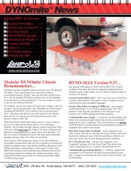
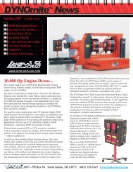
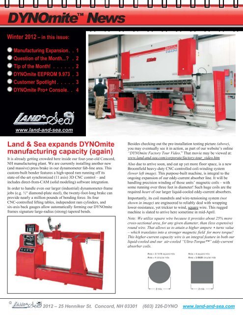
Land & Sea expands <strong>DYNO</strong><strong>mite</strong><br />
manufacturing capacity (again)<br />
It is already getting crowded here inside our four-year-old Concord,<br />
NH manufacturing plant. We are currently installing another new<br />
(and massive) press brake in our dynamometer fab-line area. This<br />
custom-built bender features a high-speed ram running off its<br />
state-of-the-art synchronized (11 axis) 3D CNC control – and<br />
includes direct-from-CAM (solid modeling) software integration.<br />
In order to handle even our larger (industrial) dynamometer-frame<br />
jobs (e.g. ½“ diamond-plate steel), the twenty-foot-long brake can<br />
provide nearly a million pounds of bending force. Its four<br />
CNC-controlled lifting tables, independent ram cylinders, and<br />
six-axis back gauges allow automatically forming our <strong>DYNO</strong><strong>mite</strong><br />
frames signature large-radius (strong) tapered bends.<br />
Besides checking out the pre-installation testing picture (above),<br />
you may eventually see it in action, as part of our website’s online<br />
“<strong>DYNO</strong><strong>mite</strong> Factory Tour Video.” That movie may be viewed at:<br />
www.land-and-sea.com/corporate/factory-tour_video.htm<br />
Also due to arrive soon, and eat up yet more floor space, is a new<br />
Broomfield heavy-duty CNC-controlled coil-winding system<br />
(lower left image). This purpose-built machine, is integral to the<br />
ongoing expansion of our eddy-current absorber line. It will be<br />
handling precision winding of those units’ magnetic coils – with<br />
some running over three feet in diameter! Such huge coils are the<br />
required heart of our larger liquid-cooled eddy-current absorbers.<br />
Importantly, its coil mandrels and wire-tensioning system (not<br />
shown in image) are engineered to reliably deal with wrapping<br />
lower-resistance, yet trickier to wind, square wire. This rugged<br />
machine is slated to arrive here sometime in mid-April.<br />
Note: We utilize square wire because it provides about 25% more<br />
cross-sectional area, for any given diameter, than (less expensive)<br />
round wire. That allows us to attain a higher ampere * turns value<br />
– which translates into a stronger magnetic field for more torque!<br />
This higher-current capacity wire is an integral feature in both our<br />
liquid-cooled and our air-cooled “Ultra-Torque” eddy-current<br />
absorber coils.<br />
<br />
<strong>2012</strong> – 25 Henniker St. Concord, NH 03301 (603) 226-<strong>DYNO</strong> www.land-and-sea.com
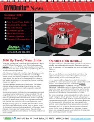
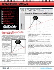
Question of the month...?<br />
“Can I change the order of the columns on my run’s Data-Points<br />
listings? I want the Hp to be on the left of my Torque column.”<br />
Sure, this is very simple to do – in <strong>DYNO</strong>-MAX 2010, as well as in<br />
the older <strong>DYNO</strong>-MAX 2000 version. Here are the steps to follow:<br />
1) As with many customization settings in <strong>DYNO</strong>-MAX, you first<br />
decide if you want this customization to apply to just this run, or all<br />
future tests. If it is a one-time thing, then perform your subsequent<br />
graph-setup steps after you save this one run’s data. Conversely, to<br />
apply your new column format for the foreseeable future, perform<br />
the graph setup changes on a “New Run” (before recording data).<br />
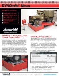
2) Open the graph-setup editor, and click on the first graph tab that<br />
you wish to alter the data-points listing column order for.<br />
3) Highlight (click on) the formula line you wish to move left on<br />
the column listing, and click the “Up” button (as shown in the<br />
example images below).<br />
4) Now examine your results (in the second pair of images below).<br />
Notice that the selected Hp formula line has moved on up in the list<br />
box. It will now appear to the left of the Torque formula column in<br />
the data-points listing. In other words, the formula-row order (in the<br />
graph-setup editor) corresponds with the the column order for the<br />
data-points listing.<br />
5) Repeat these steps to move columns into any order. Each graph<br />
tab is individually configurable, different orders may apply to each.<br />
Note: The far-left RPM (X-axis) column cannot be moved right.<br />
Tip of the Month!<br />
ZIP YOUR TEST RUN FILES FOR<br />
E-MAILING TO CUSTOMERS OR SUPPORT…<br />
<strong>DYNO</strong>-MAX 2000 first introduced features to<br />
make it easy for you to bundle up recorded<br />
runs for easy e-mailing, to your customers or<br />
support, using most MAPI-compliant e-mail<br />
packages (Messaging Application Programming<br />
Interface). You may have already used the<br />
“File - Send To - E-Mail Current Run to Land &<br />
Sea…” menu choice to automatically create a<br />
pre-addressed e-mail, with attachments, for<br />
“support@land-and-sea.com...” – ready to hit<br />
send. This was the quickest way to e-mail all<br />
an open test’s run information (.run) file, data<br />
(.raw) files, etc.<br />
However, today many people use non-MAPI<br />
internet-based e-mail programs – like Gmail or<br />
Hotmail. For them, the above method is out.<br />
Fortunately, if you run <strong>DYNO</strong>-MAX 2010, this<br />
need not be an issue. Simply click on the “File<br />
- Send To - Zip Current Run for E-Mailing to<br />
Owner” choice. It automatically creates an<br />
appropriately named, zipped file on your<br />
Desktop, ready for attaching to any e-mail.<br />
Note: You may even set an alternate ‘copy<br />
location’ from the “Tools - Preferences -<br />
General” tab.<br />
The above “Owner” menu choice will include<br />
just the files your customer would need to<br />
review their runs (e.g. using the free Demo<br />
download of <strong>DYNO</strong>-MAX 2010). Naturally, there<br />
is also a “File - Send To - Zip Current Run for<br />
E-Mailing to Support” option. It works the<br />
same way, but bundles in all the relevant<br />
setting and log files that help our support<br />
technicians and engineers to answer your<br />
<strong>DYNO</strong>-MAX related questions.<br />
We actively encourage <strong>DYNO</strong>-MAX 2010 users,<br />
who are under a current Priority Support Plan,<br />
to take advantage of the program’s built-in<br />
zipping and/or e-mail technical-support<br />
features. If your PC or laptop has e-mail<br />
capability, help is only a couple of mouse<br />
clicks away.<br />
<br />
<strong>2012</strong> – 25 Henniker St. Concord, NH 03301 (603) 226-<strong>DYNO</strong> www.land-and-sea.com
<strong>DYNO</strong><strong>mite</strong> EEPROM Version<br />
9.973 is now available<br />
Operators running our <strong>DYNO</strong><strong>mite</strong>-Pro (or Lite) may update to<br />
EEPROM version 9.973 – as always, this is a free upgrade. This<br />
verison adds the following two enhancements:<br />
There is now support for a new “Minimum Hold RPM-C” loadcontrol<br />
parameter. This new parameter specifies an absorber<br />
RPM that must be exceeded before the <strong>DYNO</strong><strong>mite</strong> auto-load<br />
control will apply any power absorption. The resulting delay<br />
helps avoid excessive “off the line” stalling or loading, during<br />
hard chassis-dynamometer launching – from near zero MPH.<br />
Such overloading is typically only an issue when utilizing an<br />
absorber capable of delivering significant low-speed resistance<br />
(e.g. large AC-motor or hydraulic-gear absorbers).<br />
This setting is end-user accessible from the <strong>DYNO</strong>-MAX “Pro”<br />
“Electronics - Configure <strong>DYNO</strong><strong>mite</strong> Controls” screen, of the<br />
new <strong>DYNO</strong>-MAX 2010 versions – 10.17 (or later). Be aware, it<br />
is only applicable in “RPM Source #3 (RPM-A, RPM-C)” mode<br />
– and while operating at a relatively low shift ratio. “Out of the<br />
box,” this new setting initially defaults to 0 RPM.<br />
Adds RPM-C “Smart Latency” synchronization, for improving<br />
the inertial-compensation accuracy and the inertial-torque data<br />
smoothness – meaning less spiky. Providing accurate inertial<br />
compensation, for the flywheel-energy involved in spinning up<br />
(engine, absorber and/or chassis roller) masses, requires precise<br />
acceleration measurements. It also demands that this interruptderived<br />
(RPM-encoder based) acceleration data be kept in phase<br />
(time) with the sampled (strain-gauge based) torque data. This is<br />
easier said than done, since the encoder refresh rate increases<br />
with RPM, while the torque data has a fixed time lag (based on<br />
circuit capacitance). Smart Latency utilizes sliding frames, with<br />
micro-second interpolation, to minimize RPM/time/torque shift –<br />
resulting in more accurate data out.<br />
The new EEPROM, with Smart Latency, does not require adding<br />
higher-count encoders to see the benefits of the new algorithms.<br />
In fact, even systems running just a single pulse-per-revolution<br />
RPM source (1 PPR) will often attain acceleration RPM data<br />
smoothness and “inertial versus measured” torque<br />
synchronization that surpasses systems running encoders with<br />
counts of 60, 100, or even 1,024 lines.<br />
To get the EEPROM upgrade, obtain the required flash update file<br />
– either from an e-mail (from Support) or via our online downloads<br />
(as described below):<br />
<strong>DYNO</strong>-MAX operators who have their dynamometer’s PC online,<br />
may select “Electronics - Display <strong>DYNO</strong><strong>mite</strong> Parameters...” and<br />
then click the “Check for Updates...” button. Or, using any PC with<br />
Internet access, you may visit our web site’s <strong>DYNO</strong><strong>mite</strong> Support<br />
Documents section to download the update file. Before flashing, be<br />
sure to review the “Electronics - Flash <strong>DYNO</strong><strong>mite</strong> Firmware” help<br />
topic in <strong>DYNO</strong>-MAX.<br />
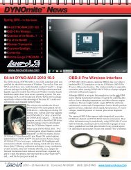
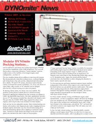
Customer Spotlight<br />
Gifford Brothers Racing<br />
Howard Gifford, of Ottawa Ontario Canada, has been<br />
in the top level of oval track snowmobile racing since 1975. In<br />
2007 he won the Eastern Pro Tour Champ 440 season-points<br />
championship. After winning that, Howard retired from driving,<br />
and today, Gifford Brothers Racing specializes in designing and<br />
building hydroformed pipes – for most of the top race teams.<br />
Howard says “the exhaust on a two stroke is where 75% of the<br />
power comes from. A two-stroke pipe is a supercharger – without<br />
moving parts. It uses sonic waves to extract a fresh charge into<br />
the pipe, stuffing it back into the cylinder (trapped) at the precise<br />
moment the exhaust-port closes. Without a dyno, development of<br />
race pipes is almost impossible. Until recently, I relied on someone<br />
else’s dyno, but that li<strong>mite</strong>d my ability to perfect my designs.<br />
“By hydroforming, I can build a perfectly ripple-free and seamless<br />
curved pipe – within 1mm of the design spec. This is why my<br />
pipes have won more races than any other pipe builder in the<br />
Eastern Pro circuit.<br />
“My test cell started out as a 30’ x 30’ garage. I had to take into<br />
consideration that I live in a residential area – soundproofing was<br />
a must. I built a 16’ x 20’ addition as my test-cell room. The walls<br />
are built with double-offset studs with both the pink and the green<br />
insulation – along with two layers of drywall. The ceiling has 24"<br />
thick blown-in insulation. I left the existing garage door in place,<br />
to create two rooms – and act as a second sound barrier. The cell<br />
has double insulated doors, so I can even roll in a sled – to test in<br />
the chassis. Two 16" ducts in the ceiling and blowers circulate air<br />
through the gable-end wall. The exhaust is extracted through a<br />
double-muffled vacuum unit, that exits into a 5" truck muffler.<br />
Outside, the sound is barely audible.<br />
“The dyno itself now has the ability to do manual hold-RPM runs<br />
and automated-test pulls. At the push of a button it measures<br />
RPM, torque, power, BSFC, EGT, fuel flow, airflow, air-to-fuel<br />
ratio, water-in and water-out temp, and dyno-coolant temperature.<br />
It corrects all this with an automatic weather station that corrects<br />
to standard, SAE, JIS, or observed readings.”<br />
<br />
<strong>2012</strong> – 25 Henniker St. Concord, NH 03301 (603) 226-<strong>DYNO</strong> www.land-and-sea.com
25 Henniker Street Concord, NH 03301<br />
PRSRT STD<br />
U.S. Postage<br />
PAID<br />
Manchester, NH<br />
Permit # 425<br />
Contact Us…<br />
Land & Sea, Inc.<br />
25 Henniker Street<br />
Concord, NH 03301<br />
(603) 226-<strong>DYNO</strong><br />
www.land-and-sea.com<br />
sales@land-and-sea.com<br />
or visit your<br />
<strong>DYNO</strong><strong>mite</strong> Users’ Forum<br />
www.land-and-sea.com/forums<br />
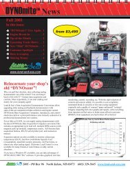
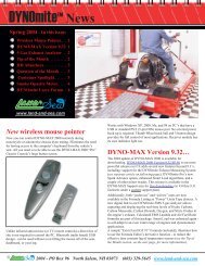
Introducing the new modular<br />
<strong>DYNO</strong><strong>mite</strong> Pro+ Console<br />
Many professional dynamometer operators require more screenmonitoring<br />
and working area than a standard <strong>DYNO</strong><strong>mite</strong> Pro<br />
Console provides. That problem is solved by the latest addition to<br />
our modular dynamometer line – the Pro + (plus) model console.<br />
This system’s modular design allows end users to create just the<br />
personalized console configuration that fits their testing needs and<br />
control-room layout. In the accompanying image (above right), a<br />
popular wrap-around design is shown. This layout is built using an<br />
extrawide dual-monitor “master” console with a pair of 45-degree<br />
“wings” and two wide-screen monitor “companion” consoles.<br />
While what to display on the monitors is ultimately up to the<br />
operator, this is what is on the above system (from left to right):<br />
Third-party fuel-mapping program<br />
Digital dyno coolant tank temperatures (with alarm relay)<br />
Redundant (from PC) <strong>DYNO</strong><strong>mite</strong> analog engine gauges<br />
<strong>DYNO</strong>-MAX 2010 “Pro” across dual monitors<br />
Digital dyno coolant pump pressure (with alarm relay)<br />
Kindle Fire with operator test program<br />
Control room video monitor<br />
Wireless remote-control tablet with <strong>DYNO</strong>-MAX<br />
The system shown could just have easily been built with only a left<br />
or right wing, or as one very long array of standard, wide-screen,<br />
and/or dual-screen stations. If your dyno-cell layout requires it, the<br />
modular units can even be configured in a 270-degree semi-circle<br />
ring. Note: The wings may be ordered with custom combinations of<br />
digital gauges, relay controls, audio speakers, AFR readouts, and<br />
wireless accessories.<br />
<br />
<strong>2012</strong> – 25 Henniker St. Concord, NH 03301 (603) 226-<strong>DYNO</strong> www.land-and-sea.com