Learning About Options in Fiber - Cables Plus USA
Learning About Options in Fiber - Cables Plus USA
Learning About Options in Fiber - Cables Plus USA

You also want an ePaper? Increase the reach of your titles
YUMPU automatically turns print PDFs into web optimized ePapers that Google loves.
SECTION 2—FIBER-OPTIC BASICS<br />
the photons <strong>in</strong>cident on the diode material).<br />
This deals with the fundamental efficiency of the<br />
diode for convert<strong>in</strong>g photons <strong>in</strong>to free electrons.<br />
• Dark Current: The thermally generated current<br />
<strong>in</strong> a diode; it is the lowest level of thermal noise.<br />
found <strong>in</strong> high-speed systems.<br />
• Complementary metal-oxide semiconductor<br />
(CMOS), which is rapidly becom<strong>in</strong>g the<br />
replacement for TTL because of its very low<br />
power consumption.<br />
• M<strong>in</strong>imum Detectable Power: The m<strong>in</strong>imum<br />
power detectable by the detector determ<strong>in</strong>ed<br />
the lowest level of <strong>in</strong>cident optical power that<br />
the detector can handle.<br />
• Response Time: The time required for the photodiode<br />
to respond to optical <strong>in</strong>puts and<br />
produce external current. Usually expressed<br />
as a rise time and a fall time, measured <strong>in</strong> tens<br />
of nanoseconds.<br />
TRANSMITTERS AND RECEIVERS<br />
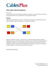
BASIC TRANSMITTER CONCEPTS<br />
The transmitter conta<strong>in</strong>s a driver and a source.<br />
(Refer to Figure 2-18.) The <strong>in</strong>put to the driver is the<br />
signal from the equipment be<strong>in</strong>g served. The<br />
output from the driver is the current required to<br />
operate the source.<br />
Figure 2-18—Basic Transmitter Block Diagram<br />
Driver<br />
The drive circuits of the transmitter must accept<br />
signal <strong>in</strong>put levels, then provide the output current<br />
to drive the source. Characteristics for specify<strong>in</strong>g a<br />
transmitter (or a receiver) are basically the same as<br />
would apply for any electronic circuit. These <strong>in</strong>clude:<br />
• Power supply voltages<br />
• Storage and operat<strong>in</strong>g temperature ranges.<br />
• Required <strong>in</strong>put and output voltage levels<br />
(which <strong>in</strong>dicate video, audio, TTL or ECL compatibility).<br />
• Data rate/bandwidth.<br />
• Operat<strong>in</strong>g wavelength.<br />
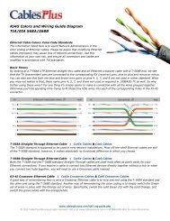
BASIC RECEIVER CONCEPTS<br />
The receiver conta<strong>in</strong>s the detector, amplifier, and<br />
output circuit. (Refer to Figure 2-19) The amplifier<br />
amplifies the attenuated signal from the detector.<br />
Figure 2-19—Basic Receiver Block Diagram<br />
Amplifier<br />
Source<br />
Detector<br />
Output Circuit<br />
Most electronic systems operate on standard,<br />
well-def<strong>in</strong>ed signal levels. Television video signals<br />
use a 1 volt peak-to-peak level.<br />
Digital systems use different standards, depend<strong>in</strong>g<br />
on the type of logic circuits used <strong>in</strong> the system.<br />
These logic circuits def<strong>in</strong>e the levels for the highs<br />
and lows that represent the 1s and 0s of digital<br />
data. Digital logic circuits, all further def<strong>in</strong>ed under<br />
the Glossary <strong>in</strong> section 3, are:<br />
• Transistor-transistor logic (TTL) used <strong>in</strong> many<br />
applications.<br />
• Emitter-coupled logic (ECL), faster than TTL<br />
and not able to be mixed with TTL, it is usually<br />
The output circuit can perform many functions,<br />
such as:<br />
• Separation of the clock and data.<br />
• Pulse reshap<strong>in</strong>g and retim<strong>in</strong>g.<br />
• Level shift<strong>in</strong>g to ensure compatibility—TTL,<br />
ECL, and so forth—with the external circuits.<br />
• Ga<strong>in</strong> control to ma<strong>in</strong>ta<strong>in</strong> constant levels <strong>in</strong><br />
response to variations <strong>in</strong> received optical<br />
power and variations <strong>in</strong> receiver operation<br />
from temperature or voltage changes.<br />
Because the receiver deals with highly attenuated<br />
light signals, it can be considered the pr<strong>in</strong>cipal<br />
component around which the design or selection<br />
2-15