Learning About Options in Fiber - Cables Plus USA
Learning About Options in Fiber - Cables Plus USA
Learning About Options in Fiber - Cables Plus USA

You also want an ePaper? Increase the reach of your titles
YUMPU automatically turns print PDFs into web optimized ePapers that Google loves.
CONNECTORS AND SPLICES<br />
The requirements for fiber-optic connection and<br />
wire connection are very different. In wir<strong>in</strong>g, two<br />
copper conductors can be jo<strong>in</strong>ed directly by<br />
solder or by connectors that have been crimped<br />
or soldered to the wires. The purpose is to create<br />
contact between the mated conductors to ma<strong>in</strong>ta<strong>in</strong><br />
a path across the junction.<br />
SECTION 2—FIBER-OPTIC BASICS<br />
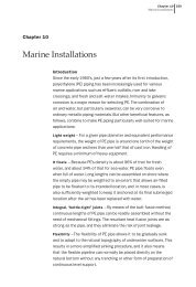
Figure 2-21—Diameter Mismatch of Connectors<br />
Concentricity<br />
Core<br />
Cladd<strong>in</strong>g<br />
Core 1<br />
Core 2<br />
Cladd<strong>in</strong>g<br />
Ellipticity (Ovality)<br />
In fiber-optics, the key to <strong>in</strong>terconnection is<br />
precise alignment of the mated fiber cores (or<br />
spots <strong>in</strong> the case of a s<strong>in</strong>gle-mode fibers) so that<br />
nearly all of the light is coupled from one fiber<br />
across the junction <strong>in</strong>to the other fiber. Precise<br />
and careful alignment is vital to the success of<br />
system operation.<br />
Core Diameter Mismatch<br />
Cladd<strong>in</strong>g Diameter Mismatch<br />
CONNECTOR REQUIREMENTS<br />
Connectors provide the mechanical means for term<strong>in</strong>at<strong>in</strong>g<br />
optical fibers to other fibers and to active<br />
devices, thereby connect<strong>in</strong>g transmitters, receivers,<br />
and cables <strong>in</strong>to work<strong>in</strong>g l<strong>in</strong>ks.<br />
The primary task of the fiber optic connector is to<br />
m<strong>in</strong>imize the optical loss across the <strong>in</strong>terface of the<br />
coupled fiber. This loss is expressed <strong>in</strong> decibels<br />
(dB). High-performance connectors are classified<br />
as those with less than 1 dB of loss; medium performance<br />
is less than 2 dB. Losses occur from <strong>in</strong>exact<br />
mat<strong>in</strong>g of the fibers, and the surface condition of<br />
the fiber ends. (See Figure 2-21.)<br />
The second task of the connector is to provide<br />
mechanical and environmental protection and stability<br />
to the mated junction. Lastly, the connector<br />
design should permit rapid and uncomplicated<br />
term<strong>in</strong>ation of a cable <strong>in</strong> a field sett<strong>in</strong>g.<br />
An ideal connector would encompass:<br />
• A fiber-alignment scheme yield<strong>in</strong>g low loss.<br />
• Physically small.<br />
• Rugged construction.<br />
• Easily field term<strong>in</strong>ated.<br />
• Field repairable.<br />
• Good thermal characteristics.<br />
• Offer excellent fiber/cable stra<strong>in</strong> relief.<br />
• Accessory tool<strong>in</strong>g to prepare fiber and cable.<br />
• Factory term<strong>in</strong>ated cable assemblies which<br />
enable users to field connectorize or splice<br />
assemblies us<strong>in</strong>g fusion or mechanical splices.<br />
• Be of moderate cost.<br />
CAUSES OF LOSS IN AN INTERCONNECTION<br />
Losses <strong>in</strong> fiber-optic <strong>in</strong>terconnections are caused<br />
by three factors: (1) Intr<strong>in</strong>sic, or fiber-related<br />
factors caused by variations <strong>in</strong> the fiber itself.; (2)<br />
extr<strong>in</strong>sic, or connector-related factors contributed<br />
by the connector itself; or (3) system factors contributed<br />
by the system itself.<br />
In jo<strong>in</strong><strong>in</strong>g two fibers together it would be nice to<br />
safely assume that the two are identical. However,<br />
the fact is that they usually are not. The fiber manufactur<strong>in</strong>g<br />
process allows fibers to be made only<br />
with<strong>in</strong> certa<strong>in</strong> tolerances.<br />
Under section 3, Table G, Intr<strong>in</strong>sic Loss Factors,<br />
lists the most important variations <strong>in</strong> tolerances that<br />
cause <strong>in</strong>tr<strong>in</strong>sic loss, i.e., core diameter, cladd<strong>in</strong>g<br />
diameter, numerical aperture mismatch, concentricity,<br />
ellipticity (or ovality) of core or cladd<strong>in</strong>g.<br />
Connectors and splices contribute extr<strong>in</strong>sic loss to<br />
the jo<strong>in</strong>t. The loss results from the difficulties <strong>in</strong>herent<br />
<strong>in</strong> manufactur<strong>in</strong>g a connect<strong>in</strong>g device to the exact<strong>in</strong>g<br />
tolerances that are required. The four ma<strong>in</strong> causes of<br />
loss that a connector or splice must control are:<br />
• Lateral displacement: A connector should<br />
align the fibers on their center axes. When one<br />
fiber’s axis does not co<strong>in</strong>cide with that of the<br />
other, loss occurs.<br />
2-17