PRODUCT INFORMATION SHEET the ultimate intelligent ...
PRODUCT INFORMATION SHEET the ultimate intelligent ...
PRODUCT INFORMATION SHEET the ultimate intelligent ...

Create successful ePaper yourself
Turn your PDF publications into a flip-book with our unique Google optimized e-Paper software.
12 . 7<br />
Technical Specification<br />
Hydronix Ltd<br />
70 Smithbrook Kilns,<br />
Cranleigh, Surrey GU6 8JJ<br />
Tel: +44 (0)1483 271769<br />
Fax: +44 (0)1483 276219<br />
www.hydronix.com<br />
Information given is correct at<br />
<strong>the</strong> time of publication. Hydronix<br />
reserve <strong>the</strong> right to modify and<br />
change <strong>the</strong> specification as<br />
deemed appropriate without<br />
notification.<br />
Hydronix, Hydro-Mix, Hydro-View<br />
and Hydro-Control are Trade<br />
Marks of Hydronix Limited<br />
HM:05:2000<br />
HOLE 127 Ø<br />
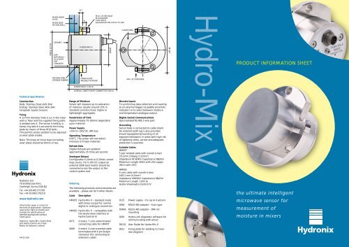
Construction<br />
Body: Stainless Steel (AISI 304)<br />
Endcap: Stainless Steel (AISI 304)<br />
Faceplate: Syalon Ceramic<br />
MIXER WEAR<br />
PLATE<br />
MIXER BASE<br />
OR SIDE WALL<br />
CERAMIC<br />
GAP<br />
NATURALLY<br />
FILLS WITH<br />
DRY<br />
CONCRETE<br />
PACKING RING<br />
(SPONGE RUBBER)<br />
Fixing<br />
A 127mm diameter hole is cut in <strong>the</strong> mixer<br />
wall or floor and <strong>the</strong> supplied fixing plate<br />
is welded over it. The sensor is held by a<br />
clamp ring which is secured to <strong>the</strong> fixing<br />
plate by means of three M10 bolts.<br />
This permits sensor position to be adjusted<br />
as wear plate erodes.<br />
Note: Thickness of mixer base (including<br />
wear plate) should be 60mm or less.<br />
15<br />
HYDRO-MIX V<br />
FIXING PLATE<br />
WELDED TO MIXER<br />
SENSOR BODY 125mm<br />
M10 x 25 HEX BOLT<br />
M10 WASHER<br />
3 OFF EACH<br />
EQUISPACED ON 143mm P.C.DIA.<br />
108 Ø<br />
OVERALL LENGTH WITH CONNECTOR 200mm<br />
Range of Moisture<br />
Sensor will measure up to saturation<br />
of material. Usually around 15% in<br />
standard concrete mixes, higher in<br />
lightweight aggregates.<br />
Penetration of Field<br />
Approximately 75-100mm dependent<br />
upon material.<br />
Power Supply<br />
+15V to +30V DC, 4W max.<br />
Operating Temperature<br />
0-60˚C. The sensor will not detect<br />
moisture in frozen materials.<br />
Refresh Rate<br />
Digital Outputs are updated<br />
approximately 25 times per second.<br />
Analogue Output<br />
Configurable 4-20mA or 0-20mA current<br />
loop source. For 0-10V DC output an<br />
external 500R load resistor should be<br />
connected across <strong>the</strong> output at <strong>the</strong><br />
control system end.<br />
Ordering<br />
The following products and accessories are<br />
available – please ask for fur<strong>the</strong>r details.<br />
Code<br />
Description<br />
HM05T Hydro-Mix V – standard mode<br />
with linear output for normal<br />
digital or analogue connection.<br />
HM05C Hydro-Mix V – compatible with<br />
<strong>the</strong> Hydro-View interface or<br />
Hydro-Control IV<br />
0071 4 metre, 7 core unterminated<br />
connecting cable for HM05T<br />
0069 4 metre, 4 core screened cable<br />
terminated with 6 pin Bulgin<br />
connector (for connecting to<br />
extension cable)<br />
CLAMP RING<br />
M8 x 35 CAPSCREW<br />
Discrete Inputs<br />
To synchronise data collection and masking<br />
to an external trigger (ie paddle proximity<br />
indicator) or to select between moisture<br />
and temperature analogue output.<br />
Digital (Serial) Communications<br />
Opto-isolated RS 485 2 wire port.<br />
Grounding<br />
Sensor body is connected to cable shield.<br />
An external earth lug is also provided.<br />
Ensure equipotential bonding of all<br />
exposed metalwork. In areas with high risk<br />
of lightning strike, correct and adequate<br />
protection is essential.<br />
Suitable Cables<br />
HM05T<br />
5 pair twisted cable with overall screen<br />
7/0.2mm (24awg, 0.22mm 2 )<br />
Impedance 92 W/Km Capacitance 98pF/m<br />
Maximum Length 400m with 24V supply<br />
(90 m with 15V)<br />
HM05C<br />
4 core cable with overall screen<br />
16/0.2 mm (0.5mm 2 )<br />
Impedance 40W/Km Capacitance 98pF/m<br />
Maximum Length 110m to<br />
Hydro-View/Hydro-Control IV<br />
0115 Power supply – for up to 4 sensors<br />
0049 RS232-485 adapter – 9 pin type<br />
0049A<br />
RS232-485 adapter – DIN rail<br />
mounting<br />
0050 Hydro-Link diagnostic software for<br />
communicating with sensor<br />
D0151<br />
User Guide for Hydro-Mix V<br />
0021 Fixing plate for welding to mixer<br />
(see diagram)<br />
165 Ø<br />
Hydro-Mix V<br />
<strong>PRODUCT</strong> <strong>INFORMATION</strong> <strong>SHEET</strong><br />
<strong>the</strong> <strong>ultimate</strong> <strong>intelligent</strong><br />
microwave sensor for<br />
measurement of<br />
moisture in mixers
Hydro-Mix V<br />
defining <strong>the</strong> standards of microwave moisture measurement<br />
Flexible positioning<br />
The Hydro-Mix V sensor may be used successfully with all static pan type<br />
mixers as indicated, and only one sensor is required. However, it is important<br />
that it is positioned in <strong>the</strong> moving flow of material where no build up on <strong>the</strong><br />
sensor face is likely to occur.<br />
For rotating pan mixers <strong>the</strong> Rotating Pan Adaptor Kit will be required.<br />
The Hydro-Mix V microwave sensor<br />
uses <strong>the</strong> unique Hydronix digital<br />
measuring techniques to provide a<br />
greater accuracy of measurement<br />
over a wider range of moisture<br />
contents than any o<strong>the</strong>r sensor on<br />
<strong>the</strong> market. Designed for rugged<br />
wear in all types of mixer, <strong>the</strong><br />
Hydro-Mix V sensor with integral<br />
signal processing provides a linear<br />
output (both analogue and serial)<br />
that may now connect directly to<br />
any control system or interface in<br />
’compatibility‘ mode with<br />
Hydronix control and interface<br />
equipment.<br />
Measuring in <strong>the</strong> mixer<br />
Auto-track – mix OK?<br />
Sensor outputs<br />
Turbo mixers<br />
1<br />
2<br />
3<br />
4<br />
Digital connection<br />
Direct with control system in<br />
‘Standard’ mode using <strong>the</strong> linear analogue<br />
or serial output, to provide a fully<br />
integrated, cost effective<br />
moisture control system.<br />
Hydro-View connection<br />
Displays and communicates<br />
moisture to control system.<br />
POWER<br />
SUPPLY<br />
Hydro-Control Jr connection<br />
A simple but accurate way of controlling <strong>the</strong><br />
addition of water in <strong>the</strong> mixer, this system is<br />
easy to install, simple to use and extremely<br />
cost effective. Can be used ‘stand alone’ or<br />
with a control system.<br />
Reading at 25 times per second <strong>the</strong><br />
sensor detects rapid changes in <strong>the</strong><br />
moisture in <strong>the</strong> materials throughout<br />
<strong>the</strong> mix cycle.<br />
Sensor configuration<br />
The sensor is configured remotely<br />
using <strong>the</strong> Hydro-Link diagnostic<br />
software. A large number of<br />
parameters are selectable, including<br />
<strong>the</strong> type of output, filtering<br />
characteristics etc.<br />
Sensor response<br />
The sensor response may be adjusted<br />
remotely using <strong>the</strong> Hydro-Link<br />
diagnostic software to eliminate <strong>the</strong><br />
effects of mixer blades and air voids<br />
within <strong>the</strong> mix <strong>the</strong>reby ensuring<br />
optimum performance for any<br />
particular type of mixer.<br />
CONTROL SYSTEM<br />
Hydro-Control IV connection<br />
Completely controls <strong>the</strong> mixing cycle to provide <strong>the</strong> correct<br />
addition of water irrespective of variation in <strong>the</strong> aggregates.<br />
This operates to a level of accuracy unachievable with any<br />
o<strong>the</strong>r system and operates in such a manner to reduce mix<br />
cycle time to a minimum consistent with <strong>the</strong> production<br />
of a homogenous mix.<br />
Ano<strong>the</strong>r important unique feature of<br />
<strong>the</strong> sensor is <strong>the</strong> inbuilt facility to<br />
indicate when <strong>the</strong> mix is<br />
homogeneous, such that <strong>the</strong> moisture<br />
reading is truly representative of <strong>the</strong><br />
entire mix. Typically, <strong>the</strong> sensor<br />
averages moisture readings for 10<br />
seconds after homogeneity is<br />
detected to achieve very high<br />
accuracy of measurement.<br />
Graphic display<br />
Using <strong>the</strong> Hydro-Link software (or<br />
when interfacing with o<strong>the</strong>r Hydronix<br />
equipment) a graphic trace may be<br />
viewed to assist in selecting <strong>the</strong> most<br />
suitable set up parameters. This<br />
information may also be used to<br />
determine <strong>the</strong> effectiveness of <strong>the</strong><br />
mixing action and whe<strong>the</strong>r any<br />
adjustments to <strong>the</strong> mixer<br />
configuration are required.<br />
Synchronised readings<br />
The sensor may be programmed only<br />
to read after a given time period after<br />
an input from (typically) a proximity<br />
switch that detects a passing blade.<br />
This facility is useful when <strong>the</strong> sensor<br />
is covered by material for only part of<br />
<strong>the</strong> mix cycle.<br />
Two modes of operation are<br />
selectable that change <strong>the</strong> sensor<br />
output.<br />
1. Standard mode:<br />
The sensor provides both a digital<br />
(serial) and analogue linear output,<br />
that may be scaled internally or<br />
externally.<br />
2. Compatibility mode:<br />
The output simulates that of <strong>the</strong><br />
previous range of Hydronix analogue<br />
sensors, and is used when replacing<br />
this type of sensor or when<br />
interfacing with <strong>the</strong> Hydro-View or<br />
Hydro-Control IV units.<br />
Calibration<br />
The linear unscaled output requires<br />
calibration to provide a meaningful<br />
moisture reading. When <strong>the</strong> sensor is<br />
connected directly to <strong>the</strong> control<br />
system, calibration should be<br />
performed in <strong>the</strong> system, or<br />
alternatively using Hydronix<br />
interface/control equipment.<br />
The facility to internally calibrate<br />
<strong>the</strong> sensor using <strong>the</strong> Hydro-Link<br />
software is also available.<br />
Temperature measurement<br />
Temperature output is available to<br />
provide readout of material<br />
temperature.<br />
Accuracy of measurement<br />
All measurements may if required be<br />
calibrated to oven dried laboratory<br />
tests to an accuracy of ± 0.1%.<br />
Wear life<br />
The ceramic faceplate is <strong>the</strong> only part<br />
exposed to wear when installed in <strong>the</strong><br />
mixer. The special composition of <strong>the</strong><br />
material used has been selected, after<br />
many years experience, for its<br />
exceptional wear characteristics.<br />
Under normal use <strong>the</strong> sensor will<br />
last for many years.<br />
The sensor may be positioned<br />
in <strong>the</strong> base of <strong>the</strong> mixer, or in<br />
<strong>the</strong> side wall providing <strong>the</strong>re<br />
is sufficient material to cover <strong>the</strong><br />
sensor. In this position <strong>the</strong> sensor<br />
is less susceptible to accidental<br />
damage and is more accessible.<br />
Bottom edge of sensor is<br />
positioned approximately<br />
50mm above mixer floor.<br />
Planetary mixers<br />
Mount <strong>the</strong> sensor in <strong>the</strong><br />
base of <strong>the</strong> mixer. Position of<br />
sensor centreline is set in from<br />
<strong>the</strong> side wall of <strong>the</strong> mixer by<br />
approximately 1/4 to 1/3 of<br />
mixer radius.<br />
Single horizontal shaft mixers<br />
Position sensor on <strong>the</strong> upside<br />
of <strong>the</strong> blade movement.<br />
Centreline of sensor mounted<br />
at approximately 10˚ angle<br />
from <strong>the</strong> vertical<br />
Twin shaft mixers<br />
Sensor positioned in end wall at<br />
<strong>the</strong> opposite end to <strong>the</strong> motors,<br />
with bottom edge of <strong>the</strong> sensor<br />
approx 75mm above mixer floor,<br />
and vertically below <strong>the</strong><br />
centreline of <strong>the</strong> shaft.