PR430S2 WEIGHT INDICATOR
PR430S2 WEIGHT INDICATOR
PR430S2 WEIGHT INDICATOR
- No tags were found...

Create successful ePaper yourself
Turn your PDF publications into a flip-book with our unique Google optimized e-Paper software.
<strong>WEIGHT</strong> <strong>INDICATOR</strong><strong>PR430S2</strong>5.3.2 ModbusRTU .................................................................................... 285.3.3 Function Codes Supported .............................................................. 295.3.4 Bits (coils)........................................................................................ 295.3.5 Holding Registers ............................................................................ 305.3.6 Identification Object ......................................................................... 315.3.7 Exception Codes ............................................................................. 316 Specification and Installation ....................................................... 326.1 Mains Supply ................................................................................... 326.2 Load Cell Excitation ......................................................................... 326.3 Input Characteristics ........................................................................ 326.4 Serial Link ........................................................................................ 326.5 Trip Outputs ..................................................................................... 326.6 Environment .................................................................................... 326.7 Enclosure Dimensions ..................................................................... 336.8 Wiring Connections.......................................................................... 346.9 Wiring Diagram: 4 Wire Load Cell Connection ................................. 356.10 Wiring Diagram: Remote Load Cell Sensing .................................... 356.11 Wiring Diagram: Relay Outputs ....................................................... 366.12 Wiring Diagram: Serial Link (RS232) ............................................... 366.13 Wiring Diagram: Serial Link (Multidrop)............................................ 376.14 EMC ................................................................................................ 387 Equipment Faults........................................................................... 397.1 Out of range .................................................................................... 397.2 Failures ............................................................................................ 407.3 Error Codes ..................................................................................... 40Issue 3.3 December, 2010 Page 3 of 40
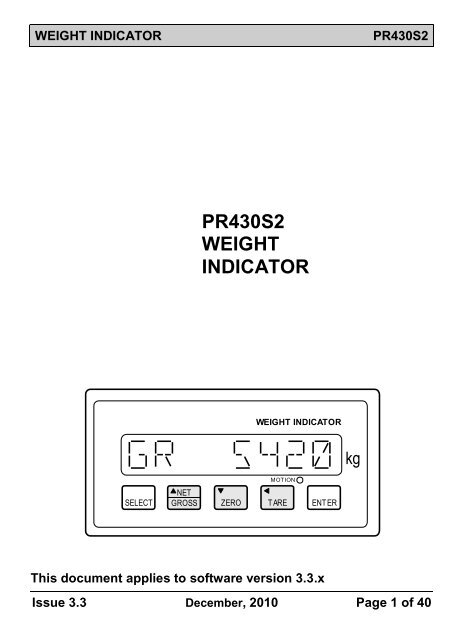
<strong>PR430S2</strong>1 Overview1.1 Description<strong>WEIGHT</strong> <strong>INDICATOR</strong>The <strong>PR430S2</strong> is a micro-processor based amplifier/indicator housedin a standard panel mounting DIN case. It features a sealed tactilepush-button panel with an 8 character LED display.The unit connects with 1-4 standard 350 ohm strain gauge load cellsto which it supplies 10VDC excitation. It amplifies and conditions theresultant signal to produce a gross weight value to 16 bit resolution(1 part in 65,536) with negligible drift. The relatively high inputresolution enables large standing weights to be accommodatedwithout loss of output resolution.NET and TARE push-buttons cater for manual (hand-add)applications, including cumulative weighing. Having completed oneweighment, operating TARE zeros the NET display ready for afurther weighment.A configurable RS232/RS485 serial link is provided. This allowscommunications with a host PC or PLC, or continuous transmissionof the weight signal to a remote display.This unit is factory calibrated to have a precise internal input range(PG setting 7 only) so that it may be replaced without the need forvessel emptying or re-calibration.An internal self-calibration feature effectively removes error due totemperature drift or other causes by reducing them to less than5ppm/°C.Being a micro-processor based product the <strong>PR430S2</strong> operates fromconfiguration and calibration settings stored in non-volatile memoryi.e. protected against loss indefinitely. The configuration andcalibration data is entered and adjusted through the front panel.Similarly the weigh scale is calibrated in a single operation, byloading a known weight and by entering its value through the frontpanel or by entering precise load cell sensitivity and capacity figures.Page 4 of 40 December, 2010 Issue 3.3
<strong>WEIGHT</strong> <strong>INDICATOR</strong><strong>PR430S2</strong>All connections to the <strong>PR430S2</strong>are made by means of pluggablescrew terminal blocks.1.2 Dual Output Trip LevelsDual trip output relays are available. These present N/O (NormallyOpen) contacts which open or close depending on the Sensesettings (ref S1, S2) when the gross weight goes above the TripLevels (T1 and T2) and change back when it falls below the TripLevels minus the Dead Bands (T1-D1 and T2-D2).1.3 Model Versions<strong>PR430S2</strong>Indicator Amplifier with Serial Interface and Dual TripsDC powered versions have a suffix 'D', e.g. <strong>PR430S2</strong>DAn optional IP65 transparent front cover is available by adding suffix'/TC' to model number, e.g. <strong>PR430S2</strong>/TC.Issue 3.3 December, 2010 Page 5 of 40
<strong>PR430S2</strong>1.4 Weigh Scale Application<strong>WEIGHT</strong> <strong>INDICATOR</strong>Load CellsSELECT<strong>WEIGHT</strong> <strong>INDICATOR</strong>MOTIONNETGROSS ZERO TARE ENTERkgLNESERIAL LINKto PC or PLCMAINS SUPPLY100-240 V AC1.5 Process Vessel ApplicationTANK EMPTYWARNINGT1STOP FILLT1T2D1DEADBANDT2START FILLTANKEMPTYLoad CellsSELECT<strong>WEIGHT</strong> <strong>INDICATOR</strong>MOTIONN ETGROSS ZERO TARE ENTERkgLNESERIAL LINKto PC or PLCMAINS SUPPLY100-240 V ACPage 6 of 40 December, 2010 Issue 3.3
<strong>WEIGHT</strong> <strong>INDICATOR</strong>2 Operation2.1 Front Panel<strong>PR430S2</strong><strong>WEIGHT</strong> <strong>INDICATOR</strong>kgSELECTMOTIONNETGROSS ZERO T AREENT ERThe <strong>PR430S2</strong> display shows both the parameter type and its value.The working display lines are listed below:GR xxxxxNT xxxxxPASS xxxGross WeightNet WeightPass Entry to modify settingsThe three centre push-buttons: NET/GROSS, ZERO and TAREcontrol the NT (Net) and GR (Gross) readouts, as shown below:NET/GROSSZEROTAREToggles the display from Net to Gross.Zeroes the Gross if within ±2% of the calibratedzero.Tares the Net.Motion LEDThe Motion LED is illuminated whenever the weight display changesby more than two adjacent values within a 5 second period.Issue 3.3 December, 2010 Page 7 of 40
<strong>PR430S2</strong><strong>WEIGHT</strong> <strong>INDICATOR</strong>2.2 Single WeighmentsWEIGHER EMPTY<strong>WEIGHT</strong> <strong>INDICATOR</strong><strong>WEIGHT</strong> <strong>INDICATOR</strong>kgkgSELECTMOTIONNETGROSS ZERO TAREENTERSELECTMOTIONNETGROSS ZERO TAREENTERLOAD 25 Kg<strong>WEIGHT</strong> <strong>INDICATOR</strong>kgSELECTMOTIONNETGROSS ZERO TAREENTERUNLOAD<strong>WEIGHT</strong> <strong>INDICATOR</strong>kgSELECTMOTIONNETGROSS ZERO TAREENTERPage 8 of 40 December, 2010 Issue 3.3
<strong>WEIGHT</strong> <strong>INDICATOR</strong>2.3 Data Entry<strong>PR430S2</strong>To enable stored parameters to be entered and modified, theNET/GROSS, ZERO and TARE keys operate as Raise, Lower andDigit Select keys whenever the display is in the data entry mode, asidentified by part or all of the displayed value flashing on/off. To edita parameter value use one of the following data entry methodsdepending upon the type of data item you wish to edit. If the valueentered is out of range it will be limited accordingly.2.3.1 Numeric Having selected the parameter to be edited, see sec 2.4,operate the ENTER key. The first digit of the parameter dataflashes on/off. Operate the Raise and Lower keys, either by momentaryoperation or by holding down the key for more rapidadjustment, until the required setting is obtained.Alternatively, use the Digit Select key to select the digit to bemodified and then use the Raise and Lower keys to modifythe individual digits until the required value is obtained. Operate the ENTER key again, the parameter data will nowstop flashing and data entry is complete.2.3.2 List of OptionsSome parameters will have a list of possible options available e.g.YES/NO, the data entry method for these is as follows. Having selected the parameter to be edited, see sec 2.4,operate the ENTER key. The parameter data text flasheson/off. Operate the Raise and Lower keys to cycle through the list ofoptions and select the required item. Operate the ENTER key again, the parameter data text willnow stop flashing and data entry is complete.Issue 3.3 December, 2010 Page 9 of 40
<strong>PR430S2</strong><strong>WEIGHT</strong> <strong>INDICATOR</strong>2.4 Access to Passcode Protected DataThe following data areas are passcode protected.Configuration DataCalibration DataThe factory default passcodes for these data areas are 1 and 2respectively. These default passcodes can be changed by the userfor additional security.To gain access to any passcode protected data areas from theworking displays operate the SELECT push-button until the indicatorshows “PASS 0”. Now enter the required passcode using thenumeric data entry method, see section 2.3.1. If the correctpasscode was entered the first item of that data area will bedisplayed.Use the SELECT push-button to cycle through the list of parameterswithin the data area.To exit the data area operate the ENTER push-button at the lastparameter i.e. at “EXIT”.2.4.1 Lost Passcodes: Restore Factory SettingsIn the event of the passcodes being lost the original factory defaultsetting of 1 and 2 can be reloaded by holding down the SELECT andENTER push-buttons for approximately 30 seconds (operate ENTERfirst). After this time the display changes to read PASS. Thepasscodes will then have been restored to the values of 1 and 2.Page 10 of 40 December, 2010 Issue 3.3
<strong>WEIGHT</strong> <strong>INDICATOR</strong>3 Configuration Data (Passcode 1)<strong>PR430S2</strong>The following configuration data is passcode protected. To gainaccess to this data a valid passcode must be entered, refer tosection 2.4 for further details.Parameter Range DefinitionWIWKT1D1YES/NO Weighing InDetermines whether the Net weightincreases or decreases as the Grossweight increases.YES – Net increases as Gross increases.NO – Net Decreases as Gross increases.FREE/LOCKWeigh KeysFree or locked. When set to LOCK theNET/GROSS, ZERO and TARE buttonsare disabled.0-99999 Trip 1 Level – KgsThe gross weight level at which T1 willswitch state, as the gross weight is rising.(Disables T1 when set to 0).0-99999 Deadband 1 – KgsThe gross weight, below Trip 1 Level, atwhich T1 will switch state, as the grossweight is falling.S1 0-1 Sense 1Determines Trip 1 sense.0 = OFF above the Trip 1 Level setting1 = ON above the Trip 1 Level settingT2D20-99999 Trip 2 Level – KgsThe gross weight level at which T2 willswitch state, as the gross weight is rising.(Disables T2 when set to 0).0-99999 Deadband 2 – KgsThe gross weight, below Trip 2 Level, atwhich T2 will switch state, as the grossweight is falling.FactorySettingYESFREE00000Issue 3.3 December, 2010 Page 11 of 40
<strong>PR430S2</strong><strong>WEIGHT</strong> <strong>INDICATOR</strong>Parameter Range DefinitionS2 0-1 Sense 2Determines Trip 2 sense.0 = OFF above the Trip 2 Level setting1 = ON above the Trip 2 Level settingBR 1200- Baud Rate - bps19200 Serial data transmission speed.CS 485/232 Communication StandardDetermines the serial link communicationstandard i.e. RS485/RS422 or RS232.SM SABUS /TRANS /ASCII /RTUSerial ModeThis allows the serial link to beconfigured for communication to aPLC/PC (SABUS, ModbusASCII orModbusRTU) or to periodically transmitthe current gross or net weight (TRANS).Refer to section 5 for further details.FactorySetting09600485SABUSParity parameter: shown only when Serial Mode = ASCII or RTU.Parameter Range DefinitionPAR NONE /EVEN /ODDParitySets the serial data parity mode. Thisonly applies to ModbusASCII orModbusRTU serial modes.FactorySettingNONEAddress parameter: shown only when Serial Mode = SABUS andCommunication Standard = 485, or when Serial Mode = ASCII or RTU.Parameter Range DefinitionADDR 0-99 AddressSets the units address code number.FactorySetting0Page 12 of 40 December, 2010 Issue 3.3
<strong>WEIGHT</strong> <strong>INDICATOR</strong><strong>PR430S2</strong>Periodic transmit parameters: shown only when Serial Mode = TRANSParameter Range DefinitionTX GR/NT Transmit Data ItemDetermines which data item will beperiodically transmitted via the serial link,when Serial Mode is set to TRANS. Theoptions are: Gross (GR) or Net (NT).IT 0.1-60.0 Transmission Interval - SecondsThe time between data transmissionswhen Serial Mode is set to TRANS.FactorySettingGR1.0Parameter Range DefinitionPSET 0-999 Passcode SetThis determines the passcode for accessto the configuration parameters.EXITEXITOperate ENTER to return to workingdisplays.Operate SELECT to cycle around to WIagain.FactorySetting1Issue 3.3 December, 2010 Page 13 of 40
<strong>PR430S2</strong>4 Calibration (Passcode 2)4.1 Calibration MethodCalibration can be achieved in one of two ways:<strong>WEIGHT</strong> <strong>INDICATOR</strong>a) By the normal method of physical loading of the weigherwith calibrated weightsOrb) by entry of the precise sensitivity and capacity figures fromthe load cells.The latter method is only recommended when a matched set of highaccuracy load cells is used and physical loading is impractical.The parameter CM (Calibration Method) is used to select one of thetwo methods defined above.To re-calibrate an existing installation go to 4.2 below.To select the weigher range and the scaling factors, prior tocalibrating a new installation, go to 4.2.3 below and then to 4.2below.Page 14 of 40 December, 2010 Issue 3.3
<strong>WEIGHT</strong> <strong>INDICATOR</strong>4.2 Calibration Procedure<strong>PR430S2</strong>Before attempting to accurately calibrate a weigher first establish:a) that the weigher is repeatable, both up and down the scale i.e.that it operates freely.b) that in the case of multiple load cell installations the load cells arecorrectly rationalised i.e. that they produce the same weight readingto the same weight applied. To do this place a weight in differentpositions so that each position loads a particular load cell more thanthe others and verify that each position produces the same reading.Each unit has a precise internal input range, factory set to 0 -200,000 for 2mV/V input on the 0 - 20mV range (PG = 7). Thisprovides for replacement of a unit without the need for re-calibrationand for calibration without physical loading of weight.NOTETo calibrate a new installation go to 4.2.3 below to set thesealing constants before proceeding with calibration.Issue 3.3 December, 2010 Page 15 of 40
<strong>PR430S2</strong>4.2.1 Calibration with WeightsNOTE: Set scaling constants before proceeding.Parameter Range DefinitionCM WTS /CALCZRZ<strong>WEIGHT</strong> <strong>INDICATOR</strong>Calibration MethodDetermines whether calibration is to be achievedby application of weights (WTS) or by calculationsbased upon precise load cell characteristics(CALC).Zero - KgsThe display shows the 'live' gross weight. Toregister the empty weight and thereby establishthe gross zero, operate the Enter, at which pointthe weight will flash, then operate the Down-arrow(display goes to Zero) followed by ENTER againto steady the display.0-200000 Zero CoefficientThis shows the value registered in ZR above andcan be entered into a replacement unit without theneed to empty the weigher.CA 0-99999 Calibration - KgsThe indicator shows the "live" gross weight. It maybe modified by entering a different weight value.The calibration procedure is:Load a known test weight. Enter the test weight inKgs by operating ENTER and using the Raise,Lower and SELECT keys followed by ENTERagain to steady the display and to establish thecalibration.G0-999999 Gain CoefficientThis shows the value registered in CA above andcan be entered into a replacement unit without theneed to recalibrate.CC 0-99999 Calibration CounterThis shows the number of calibrations to date. It isincremented by 1 max. when any number ofchanges are made to calibration prior to EXIT.Page 16 of 40 December, 2010 Issue 3.3
<strong>WEIGHT</strong> <strong>INDICATOR</strong>4.2.2 Calibration by CalculationNOTE: Set scaling constants before proceeding.Parameter Range DefinitionCM WTS /CALCZRZ<strong>PR430S2</strong>Calibration MethodDetermines whether calibration is to be achievedby application of weights (WTS) or bycalculations based upon precise load cellcharacteristics (CALC).Zero - KgsThe display shows the 'live' gross weight. Toregister the empty weight and thereby establishthe gross zero, operate the Enter, at which pointthe weight will flash, then operate the Downarrow(display goes to Zero) followed by ENTERagain to steady the display.0-200000 Zero CoefficientThis shows the value registered in ZR above andcan be entered into a replacement unit withoutthe need to empty the weigher.LC 0-99999 Load Cell Capacity - KgsSets the total load capacity of the load cells andprovides the means to calculate the calibration inconjunction with SENSITIVITY below.S0-9.99999 Sensitivity – mv/vSets the sensitivity to match that of the load cellsand provides the means to calculate thecalibration in conjunction with the Load CellCapacity above. (2.00000 Factory Setting)CC 0-99999 Calibration CounterThis shows the number of calibrations to date. Itis incremented by 1 max. when any number ofchanges are made to calibration prior to EXIT.Issue 3.3 December, 2010 Page 17 of 40
<strong>PR430S2</strong><strong>WEIGHT</strong> <strong>INDICATOR</strong>There are two error conditions which may occur specifically at thispoint in the procedure. These are:Display shows "OVER SPAN"Occurs when attempting to enter a test weight value greater than thespan setting. i.e. a vetting on the data entry. Either the test weightvalue or the SPAN setting must be incorrect.Display shows "RANG SAT" (RANGE SAT)Occurs if the load cell signal at the time of entering a test weightvalue indicates that with the current PG (Pre Gain) setting, the inputamplifier will saturate (reach its upper limit) before the current SPANsetting is reached. Possible causes are: incorrect SPAN setting, PGsetting too high for load cells, load cell faulty.Other error conditions not specific to calibration i.e. equipment faultsare listed under Section 7.Page 18 of 40 December, 2010 Issue 3.3
<strong>WEIGHT</strong> <strong>INDICATOR</strong>4.2.3 Scaling Constants<strong>PR430S2</strong>Parameter Range DefinitionDP9.9.9.9.9 Decimal PlacesMax of 4 decimal places.SP 0-99999 Span - KgsSet the full scale reading (or deflection,FSD). Used for validation check duringcalibration.FL 1-100 FilterDetermines the number of load cell inputreadings over which the weight iscalculated, from a rolling average, eachtime a reading is taken (every 50ms).FactorySettingNoDecimalPlaces910IN1 Corresponds to noaveraging.100 Corresponds to maximumaveraging.0-99999 Display Increment – KgsDetermines the minimum value by whichthe weight displays increment. 0corresponds to no suppression. Notethat this suppression does not apply tocalibration.0Issue 3.3 December, 2010 Page 19 of 40
<strong>PR430S2</strong><strong>WEIGHT</strong> <strong>INDICATOR</strong>Parameter Range DefinitionPG 0-7 Pre GainDetermines the load cell amplifier inputsensitivity from 0-2.5V to 0-20mV, asfollows:Settings Full Scale Input0 2.56V1 1.28V2 640mV3 320mV4 160mV5 80mV6 40mV7 20mVUP 0-1 Update Rate - secondsThis determines display update rate inseconds.PSET 0-999 Passcode SetDetermines the passcode for access tocalibration parametersEXITExitOperate ENTER to return workingdisplays. Operate SELECT to cyclearound to CM again.FactorySetting70.42Page 20 of 40 December, 2010 Issue 3.3
<strong>WEIGHT</strong> <strong>INDICATOR</strong>5 Serial Link5.1 Host Communications (Serial Mode = SABUS)<strong>PR430S2</strong>The <strong>PR430S2</strong> serial interface can be configured for RS232communication to provide a point-to-point data link or for RS485communications in order to provide multidrop bus communicationwith up to 32 units connected to a host PC or PLC.5.1.1 Point-to-Point (RS232)RS232To hostcomputeror PLC<strong>PR430S2</strong>Communication with the host is by ASCII character messages of thefollowing format:[!] [Command] [Data] [CR]where CR is the carriage return character.The ! character is followed by a two character command.Depending on the command an optional data segment follows and isterminated by a CR.Example of a request by the host for the current gross weight.Host Sends!GR[CR]<strong>PR430S2</strong> Sends!GR12345[CR]Serial Data Format:Parity = None Stop Bits = 1 Data Bits = 8Issue 3.3 December, 2010 Page 21 of 40
<strong>PR430S2</strong>5.1.2 Multidrop Bus (RS485)<strong>WEIGHT</strong> <strong>INDICATOR</strong>RS485Single Twisted PairTo hostcomputeror PLC<strong>PR430S2</strong># 1 # 2 # 3Communication with the host is by ASCII character messages of thefollowing format:[!] [Address] [Command] [Data] [CR]where CR is the carriage return character.The ! character is followed by a two character address that specifiesthe target unit. A two character command follows the address.Depending on the command an optional data segment follows and isterminated by a CR.Example of a request by the host for the current gross weight fromstation 02.Host Sends!02GR[CR]<strong>PR430S2</strong> Sends!02GR12345[CR]Serial Data Format:Parity = None Stop Bits = 1 Data Bits = 8Page 22 of 40 December, 2010 Issue 3.3
<strong>WEIGHT</strong> <strong>INDICATOR</strong>5.1.3 Command Set<strong>PR430S2</strong>Command Range DefinitionGR 0-99999 Gross Weight – KgsReturns the gross weight, scaled by DP.NT 0-99999 Net Weight – KgsReturns the net weight, scaled by DP.RD 0-200000 Read Raw DataReturns the factory calibrated load cell inputvalue.DP 0-4 Decimal PlacesReturn the number of decimal places applied tothe gross and net weight values.ZGZero GrossSets the gross weight to zero if within ±2% ofTNthe calibrated zero.Tare NetTares the net weight.ER 0-9999 ErrorReturns the error code as defined by the tablein section 7.3.Issue 3.3 December, 2010 Page 23 of 40
<strong>PR430S2</strong>5.1.4 Command DefinitionsThe general format of command strings is as follows:! aa CC nnnnnn [CR]<strong>WEIGHT</strong> <strong>INDICATOR</strong>Where:! : Delimiter characteraa : 2 digits representing the station address(only present if set to RS485 standard)CC : 2 letters representing the commandn to nnnnnn : 1 to 6 digits representing the valueassociated with the command. The value isscaled by the appropriate decimal placesetting as no decimal place character istransmitted[CR] : Carriage returnNote: the number of digits is fixed for agiven command. If an error is present thenthen the unit will return the error commandand data instead of the command and datarequested, as below.5.1.4.1 GR : Gross WeightCommand : Return the Gross WeightFormat: ! aa GR nnnnn[CR]Example:HOST SENDS!02GR[CR]<strong>PR430S2</strong> RETURNS!02GR00050[CR]Station 02 Gross Weight = 50Page 24 of 40 December, 2010 Issue 3.3
<strong>WEIGHT</strong> <strong>INDICATOR</strong>5.1.4.2 NT : Net WeightCommand : Return the Net Weight<strong>PR430S2</strong>Format: ! aa NT nnnnn[CR]Example:HOST SENDS!02NT[CR]<strong>PR430S2</strong> RETURNS!02NT00050[CR]Station 02 Net Weight = 505.1.4.3 RD : Read Raw DataCommand : Return the load cell input value in the range0 - 200000.Format: ! aa RD nnnnnn [CR]Example:HOST SENDS!02RD[CR]<strong>PR430S2</strong> RETURNS!02RD123456[CR]Station 02 load cell value = 1234565.1.4.4 DP : Decimal PlacesCommand : Return the DP setting which defines the number ofdecimal places applied to the gross/net weight.Format: ! aa DP n [CR]Example:HOST SENDS!02DP[CR]<strong>PR430S2</strong> RETURNS!02DP1[CR]Station 02 returns the FDP settingwhich defines Flow value decimal placesIssue 3.3 December, 2010 Page 25 of 40
<strong>PR430S2</strong>5.1.4.5 ZG : Zero GrossCommand : Zero the gross weight<strong>WEIGHT</strong> <strong>INDICATOR</strong>Format: ! aa ZG [CR]Example:HOST SENDS!02ZG[CR]<strong>PR430S2</strong> RETURNS!02ZG[CR]5.1.4.6 TN : Tare NetCommand : Tare the net weightFormat: ! aa TN [CR]Example:HOST SENDS!02TN[CR]<strong>PR430S2</strong> RETURNS!02TN[CR]5.1.4.7 ER : ErrorCommand : Returns the error code as defined by thetable in section 7.3.Format: ! aa ER nnnn [CR]Example:HOST SENDS!02ER[CR]<strong>PR430S2</strong> RETURNS!02ER0000[CR]Station 02 returns no error codePage 26 of 40 December, 2010 Issue 3.3
<strong>WEIGHT</strong> <strong>INDICATOR</strong><strong>PR430S2</strong>5.2 Remote Display Application (Serial Mode = TRANS)5.2.1 OverviewIt is possible to drive up to 32 remote display units from the RS485serial interface of the <strong>PR430S2</strong>, as shown below.RS485Single Twisted Pair<strong>PR430S2</strong>Remote Display# 1Remote Display# 2The <strong>PR430S2</strong> can transmit the gross or net weight at a transmissioninterval of between 0.1 and 60.0 seconds. Refer to the Transmit DataItem and Transmission Interval parameters within section 3 forfurther details.5.2.2 Data FormatThe data item is transmitted as an ASCII string, including decimalplace if configured, as follows:“[STX]00_ _ _12345[CR]”“[STX]00_ _ _1234.5[CR]”no decimal places configuredone decimal place configuredwhere_ is a leading space[STX] is ASCII character code 0x02 (start transmission)[CR] is a carriage return5.2.3 Compatible DisplaysThe following serial display units are compatible with the <strong>PR430S2</strong>. Practicon Ltd – PR330S2. London Electronics – Fusion Series.Issue 3.3 December, 2010 Page 27 of 40
<strong>PR430S2</strong><strong>WEIGHT</strong> <strong>INDICATOR</strong>5.3 Modbus Communications (Serial Mode = ASCII or RTU)The <strong>PR430S2</strong> serial interface can be configured for ModbusASCII orModbusRTU communication in either RS232 mode to provide apoint-to-point data link or in RS485 mode in order to providemultidrop bus communication with up to 32 units connected to a hostPC or PLC.5.3.1 ModbusASCIIModbusASCII uses the following serial data format:Data bits: 7Parity: None, Even or Odd (see section 3)Stop bits: 2 if parity is set to none,1 if parity is set to even or oddWith parity checkingStart 1 2 3 4 5 6 7 Parity StopWithout parity checkingStart 1 2 3 4 5 6 7 Stop Stop5.3.2 ModbusRTUModbusRTU uses the following serial data format:Data bits: 8Parity: None, Even or Odd (see section 3)Stop bits: 2 if parity is set to none,1 if parity is set to even or oddWith parity checkingStart 1 2 3 4 5 6 7 8 Parity StopWithout parity checkingStart 1 2 3 4 5 6 7 8 Stop StopPage 28 of 40 December, 2010 Issue 3.3
<strong>WEIGHT</strong> <strong>INDICATOR</strong>5.3.3 Function Codes SupportedFunction Code0x010x030x050x060x100x2B<strong>PR430S2</strong>DescriptionREAD COILSUsed to read the status of the 2 trip outputs.READ HOLDING REGISTERSUsed to read the gross & net weights, error codeand decimal places setting.WRITE SINGLE COILUsed to set the "Tare Net", "Zero Gross" or“Switch Display” bits to perform the appropriateaction. These flags are auto-cancelling after theaction has been performed.NOTE: If the zero gross cannot be performed,the error code will be set to 1814. The error codeholding register should therefore be read afterthe zero gross bit is set to determine if the actionwas successful.WRITE SINGLE REGISTERUsed to write a single holding register value. Thisfunction code is only appropriate for writing to theSense parameters as all other writable valuesspan multiple registers.WRITE MULTIPLE REGISTERSUsed to write multiple configuration values in onemessage.ENCAPSULATED INTERFACE TRANSPORTUsed with MEI Type 14 to read the deviceidentification object.5.3.4 Bits (coils)Coil Number Address Description1 0x00 Trip 1. This bit is read-only.2 0x01 Trip 2. This bit is read-only.3 0x02 Tare Net. This bit is write-only.4 0x03 Zero Gross. This bit is write-only.Issue 3.3 December, 2010 Page 29 of 40
<strong>PR430S2</strong><strong>WEIGHT</strong> <strong>INDICATOR</strong>Coil Number Address Description5 0x04 Switch Display between Gross andNet. This bit is write-only.Set this bit OFF to show the Gross.Set this bit ON to show the Net.5.3.5 Holding RegistersRegisterNumberAddress1 – 2 0x00,0x013 – 4 0x02,0x03Read /WriteReadonlyReadonly5 0x04 Readonly6 0x05 Readonly7 – 8 0x06, Read/0x07 Write9 – 10 0x08,0x09Read/WriteDescriptionGross weight. This value is 32-bitslong and therefore register addresses0x00 and 0x01 together form thegross weight value. Address 0x00contains the most significant 2 bytes.Net weight. This value is 32-bits longand therefore register addresses0x02 and 0x03 together form the netweight value. Address 0x02 containsthe most significant 2 bytes.Error code. The current error codewill be cleared after this register isread. See section 7.3 for a list of errorcodes.Decimal Places.Trip 1 Level. This value is 32-bitslong and therefore register addresses0x06 and 0x07 together form the netweight value. Address 0x06 containsthe most significant 2 bytes.Trip 2 Level. This value is 32-bitslong and therefore register addresses0x08 and 0x09 together form the netweight value. Address 0x08 containsthe most significant 2 bytes.Page 30 of 40 December, 2010 Issue 3.3
<strong>WEIGHT</strong> <strong>INDICATOR</strong>RegisterNumberAddress11 – 12 0x10,0x1113 – 14 0x12,0x13Read /WriteRead/WriteRead/Write15 0x14 Read/Write16 0x15 Read/WriteDescription<strong>PR430S2</strong>Trip 1 Deadband. This value is 32-bits long and therefore registeraddresses 0x10 and 0x11 togetherform the net weight value. Address0x10 contains the most significant 2bytes.Trip 2 Deadband. This value is 32-bits long and therefore registeraddresses 0x02 and 0x03 togetherform the net weight value. Address0x02 contains the most significant 2bytes.Trip 1 Sense.Trip 2 Sense.5.3.6 Identification ObjectThe Basic Device Identification is implemented and is available as astream and as individual objects.Object IDDescription0x00 Vendor name.0x01 Product code / model number.0x02 Software revision.5.3.7 Exception CodesThe follow exception codes may be returned by the <strong>PR430S2</strong>.CodeDescription01 Illegal Function. The function code is not supported.02 Illegal Data Address. The address of the register or thecombination of address + number of registers is invalid.03 Illegal Data Value. The value specified in the request isinvalid, e.g. the data length is incorrect.03 Slave Device Failure. An unrecoverable error occurred,e.g. the configuration value could not be saved.Issue 3.3 December, 2010 Page 31 of 40
<strong>PR430S2</strong>6 Specification and Installation6.1 Mains SupplySupply:Power consumption:Internal Fuse:6.2 Load Cell Excitation<strong>WEIGHT</strong> <strong>INDICATOR</strong>85-264VAC 50-60 Hz, or 10-36VDC10VA max.Wire ended Wickman 1A Anti-Surgetype TR5.10V DC @ 125mA max, up to four 350 ohm load cells may beconnected in parallel, 4 or 6 wire, remote sensing for volt-dropcompensation in long cables.6.3 Input CharacteristicsRange:Filter:Accuracy:6.4 Serial Link0-20mV min, 0-2.5 max.adjustable 0.2 to 20Hz.Up to 65,000 divisions with negligible drift dueto internal self correction.Standard: The serial link may be configured to RS232 orRS422/485 by means of the Communication Standard(CS) parameter, see section 3.Speed: 1200-19200bps.6.5 Trip OutputsVoltage: 250VAC or 30VDCCurrent: 5APower: 1250 VA or 150 Watts6.6 EnvironmentOperating:Storage:0 to +50°C, 20 to 75% RH Non-condensing-20 to +80°CPage 32 of 40 December, 2010 Issue 3.3
8110226872<strong>WEIGHT</strong> <strong>INDICATOR</strong><strong>PR430S2</strong>6.7 Enclosure Dimensions144<strong>WEIGHT</strong> <strong>INDICATOR</strong>kgSELECTMOTIONNETGROSS ZERO TAREENTER138PANELCUT-OUTREARCONNECTORSREMOVABLESCREWCLAMPSThe enclosure is also available with an IP65 transparent front cover.See section 1.3 for model number.Issue 3.3 December, 2010 Page 33 of 40
+VE+SE+IN-IN-SE-VE+R-TGDT1T2ENL<strong>PR430S2</strong>6.8 Wiring Connections<strong>WEIGHT</strong> <strong>INDICATOR</strong>SUPPLYTRIPSSERIALLOADCELL85-264 VACPage 34 of 40 December, 2010 Issue 3.3
LOAD CELLLOAD CELL<strong>WEIGHT</strong> <strong>INDICATOR</strong>6.9 Wiring Diagram: 4 Wire Load Cell Connection<strong>PR430S2</strong>UP TO APPROX 25 METRESLOADCELLINPUT +OUTPUT +OUTPUT -INPUT -+VE+SE+IN-IN-SE-VE<strong>PR430S2</strong>SCREEN6.10 Wiring Diagram: Remote Load Cell SensingOVER 25 METRES4 WIRELOADCELLINPUT +OUTPUT +OUTPUT -INPUT -+VE+SE+IN-IN-SE-VE<strong>PR430S2</strong>6 WIRELOADCELLINPUT +SENSE +OUTPUT +OUTPUT -SENSE -INPUT -ALTERNATIVE CONNECTIONFOR 6 WIRE LOAD CELLThe amplifier provides for remote sensing to compensate for voltdropin long leads to load cells. It is recommended that remotesensing be adopted for maximum temperature stability where cableslonger than 25 metres are to be used.Issue 3.3 December, 2010 Page 35 of 40
<strong>PR430S2</strong>6.11 Wiring Diagram: Relay Outputs<strong>WEIGHT</strong> <strong>INDICATOR</strong><strong>PR430S2</strong>VOLT-FREECONTACTST1CONTROL SUPPLY0 - 240V AC0 - 30V DCT26.12 Wiring Diagram: Serial Link (RS232)<strong>PR430S2</strong>Host+R-TGDScreenTransmitReceiveGroundPage 36 of 40 December, 2010 Issue 3.3
<strong>WEIGHT</strong> <strong>INDICATOR</strong>6.13 Wiring Diagram: Serial Link (Multidrop)<strong>PR430S2</strong><strong>PR430S2</strong>Load Cell AmplifierBUS+R-TGDBUS UP TO1000 METRESHostRS485 BUS+-GBus Cable Specification:Single twisted pair screened data transmission cable e.g. Belden8761 available from Farnell, order code 761278 for 152m reel.Issue 3.3 December, 2010 Page 37 of 40
<strong>PR430S2</strong>6.14 EMC<strong>WEIGHT</strong> <strong>INDICATOR</strong>The <strong>PR430S2</strong> complies with the European EMC directive2004/108/EC and has been tested to the following standard:EN 61326-1Immunity & Emission StandardElectrical Equipment for Measurement Control andLaboratory UsePage 38 of 40 December, 2010 Issue 3.3
<strong>WEIGHT</strong> <strong>INDICATOR</strong>7 Equipment Faults7.1 Out of range<strong>PR430S2</strong>This condition occurs if the load cell input signal is outside the fullscale range as defined by the amplifier pre-gain (parameter PGunder 4.2.3 above).Display shows "ADC-SAT+"Indicates that the input is outside the range in the positive direction.Either the signal is too large due to a load cell fault or the pre-gain(PG) is set too high.Display shows "ADC SAT-"Indicates that the input is outside the range in the negative direction,i.e. below zero.Display shows "SENSE ER"Indicates that the sense voltage is no longer within 3V of the voltageregistered at calibrationIssue 3.3 December, 2010 Page 39 of 40
<strong>PR430S2</strong>7.2 Failures<strong>WEIGHT</strong> <strong>INDICATOR</strong>Although unlikely, the following types of equipment failure arepossible. In all cases the unit may be returned to Practicon for repair.No ResponseNo indication or response of any kind. Possibly a supply circuitfailure.A soldered-in PCB (Printed Circuit Board) fuse may need replacingas a result. Alternatively the fuse failure could be the only fault.Display shows "REGFAULT"This occurs if the internal 10V load cell supply is overloaded i.e.>150mADisplay shows "ERR nnnn" where nnnn Fault Code NumberThis indicates that a micro-processor fault has occurred. It may helpto report the Fault Code Number to Practicon when returning the unitfor repair.7.3 Error CodesError CodeDescription0000 No error1810 Out of range load cell signal-negative (ADC SAT-)1811 Out of range load cell signal-positive (ADC SAT +)1814 Weigher is too loaded to zero the gross (MAX ZERO)1818 Load cell supply fault (REGFAULT)1821 Load cell sense voltage fault (SENSE ER)Note: any other error code would be due to internal errors andshould be reported to Practicon.Page 40 of 40 December, 2010 Issue 3.3