By-Pass ventiler By-Pass valves - Alflow
By-Pass ventiler By-Pass valves - Alflow
By-Pass ventiler By-Pass valves - Alflow

You also want an ePaper? Increase the reach of your titles
YUMPU automatically turns print PDFs into web optimized ePapers that Google loves.
<strong>By</strong>-<strong>Pass</strong> <strong>ventiler</strong><br />
<strong>By</strong>-<strong>Pass</strong> <strong>valves</strong>
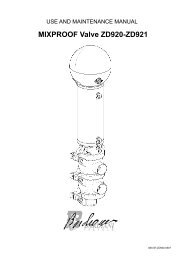
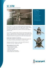
ZS1<br />
ZS1 Ventil<br />
<strong>By</strong> <strong>Pass</strong><br />
justerbar fjeder<br />
ZS1 ventilen er designet til anvendelse i forskellige<br />
sektorer, og bruger i vid udstrækning<br />
de samme komponenter som ZP serien. Den<br />
kompakte udformning og brede anvendelighed<br />
gør ventilen anvendelig i et utal af applikationer.<br />
ZS1 ventilen anvendes som sikkerhedsventil<br />
og overtryksventil, og finder anvendelse i<br />
en lang række industrier. En fjeder holder et<br />
defineret tryk på keglen, og forskellige tryk<br />
kan sættes afhængigt af hvilke fjedre der<br />
anvendes og afhængigt af hvilken indstilling<br />
fejderen via håndtaget er indstillet til.<br />
ZS1 valve<br />
<strong>By</strong> <strong>Pass</strong><br />
adjustable spring<br />
Designed for various sectors the <strong>By</strong>-<strong>Pass</strong><br />
by Bardiani Valvole uses a large part of<br />
the components from the ZP. Its compactness<br />
and versatility enable it to cover a<br />
myriad of applications. ZS1 valve is used<br />
as a pressure relief valve and by-pass;<br />
it meets the requirements of various industries.<br />
A spring maintains a load on<br />
the valve plug; different pressures can<br />
be set by using different type of springs<br />
and a threaded loader gives at the spring<br />
different strengths.<br />
2
Tekniske data<br />
Technical details<br />
Ventildesign<br />
Ventilhuse er fremstillet af massivt rustfrit stål. Dette giver ventilhuse<br />
maksimal styrke til at undgå skævheder og spændinger, som kan opstå<br />
ved svejseprocesser.<br />
- Tilslutninger fra DN10 til DN100: DIN, SMS, IDF, BS(RJT), ISO, Clamp,<br />
Flange (andre tilslutninger på forespørgsel)<br />
- max. arbejdstryk: 10 bar (145 psi)<br />
- max. tæthedstryk: se tabel<br />
- min. arbejdstryk: Fuld vakuum<br />
- max. produkt temperatur: 140°C<br />
- min. produkt temperatur: -10°C<br />
- produktberørt materiale: AISI 316L (1.4404)<br />
- produktberørte pakninger (FDA): EPDM, FKM, MVQ(Silicone), NBR<br />
eller P.T.F.E (andre materialer på forespørgsel)<br />
- produktberørt overfladefinish: Ra0.8μm (anden overfladefinish på<br />
forespørgsel).<br />
- overflade ruhed i kontakt med produkt: Ra0.8μm (andre overflader<br />
på forespørgsel).<br />
Valve structure<br />
Valve bodies are made from solid stainless steel bar. This provides<br />
valve bodies with maximum strength avoiding any flaws and stresses<br />
that may occur from welding processes.<br />
-connections from DN10 to DN100: DIN, SMS, IDF, BS(RJT), ISO,<br />
Clamp, Flange (different connections upon request)<br />
-max. working pressure: 10 bar (145 psi)<br />
-max. seal pressure: see table<br />
-min. working pressure: full vacuum<br />
-max. product temperature: 140°C (284°F)<br />
-min. product temperature: -10°C (14°F)<br />
-material in contact with the product: AISI 316L (1.4404)<br />
-gaskets in contact with the product: (homologation FDA): EPDM,<br />
FKM, MVQ (Silicon), NBR and P.T.F.E. (other seals available upon<br />
request)<br />
-finish on surfaces in contact with the product: Ra0.8μm (other<br />
types of surface finish upon request).<br />
3
ZS1<br />
Hus med varmekappe<br />
Ventiler med varmekappe anvendes typisk<br />
for at modvirke størkning af smeltet produkt.<br />
Varmt vand der cirkulerer i kappen<br />
hjælper med at opretholde temperaturen<br />
og holde produktet flydende. Denne egenskab<br />
er også med til at forlænge pakningslevetiden.<br />
Anvendes typisk iforbindelse med<br />
produkter som voks og fedt.<br />
Jacket body<br />
A heated body jacket is typically used to<br />
avoid the solidification of melted products.<br />
Hot water circulating in the jacket helps<br />
to maintain the temperature and product<br />
fluidity. It also helps to extend gasket life.<br />
Typically used on fats and waxes.<br />
Reguleringskegle<br />
Kegler med regulerings karakteristik tillader<br />
en bedre lukke karakteristik.<br />
Parabolic shutter<br />
The parabolic profile of the shutter allows<br />
a better closing operation.<br />
Special varianter<br />
Different solutions<br />
Dampspærre<br />
En dampspærre er anbefalet iforbindelse<br />
med højhygiejniske applikationer såsom<br />
sterile og aseptiske processer eller<br />
højtemperatur sterilisering. Dampspærren<br />
minimerer risikoen for at produkt kommer<br />
i kontakt med den omgivende atmosfære.<br />
Dampspærren kan anvendes i vakum systemer,<br />
hvor kun en minimal mængde damp<br />
er tilladt at komme ind i ventilen.<br />
Steam barrier<br />
A steam barrier is recommended for very<br />
hygiene duties such as sterile, aseptic processing<br />
or high temperature sterilization.<br />
The steam barrier, placed on the valve<br />
body minimises the risk of the product<br />
coming into contact with the external<br />
atmosphere. A steam barrier can be used<br />
on a vacuum system, in which case only a<br />
small amount of steam is allowed to enter<br />
the valve.<br />
Dampspærre / Steam barrier<br />
Stålmembran<br />
Rustfri stålmembraner muliggør en sikker adskillelse mellem<br />
produktet og den omgivende atmosfære. Den er monteret<br />
mellem ventilhus og kegle. Den fungerer som en dampspærre,<br />
men kræver ikke damp.<br />
Fordelene omfatter større fleksibikitet og reducerede omkostninger.<br />
I relation til varmefølsomme produkter, forhindrer stålmembraner<br />
høje temperaturer, som er forbundet med dampspærre.<br />
Membranens rengøringsmuligheder gør den meget hygiejnisk.<br />
Metallic bellows<br />
Stainless steel metallic bellows allows a safe separation<br />
between the product and the external atmosphere. It is<br />
mounted between the valve body and the shutter. It acts<br />
like a steam barrier, but without requiring steam. Benefits<br />
include greater flexibility and reduced costs. On heat<br />
sensitive products, bellows avoid the high temperatures<br />
associated with steam barriers. Its clean features make it<br />
very hygiene.<br />
• kontinuerlig sterilitet<br />
Non stop sterility<br />
• Anlæg med risko for vakum<br />
Plant with negative pressures<br />
• Lav trykfald<br />
Lower friction loses<br />
• Nem servicering<br />
Easy maintenance<br />
Stålmembran / Metallic bellows<br />
• Ideel løsning for alle temperatur områder<br />
Ideal solution for all the temperatures<br />
• Ingen anvendelse af damp<br />
No use of steam or other devices<br />
• anvendelig og billig<br />
Versatile and cheap<br />
• Nem servicering<br />
Easy maintenance<br />
Specielle optioner og varianter på forespørgsel<br />
På forespørgsel kan forskelligt tilbehør, og varianter leveres for hele ventilrækken. Det gælder også specielt udformede tilslutninger, dimensioner,<br />
eller andre skræddersyede løsninger. Teknisk rådgivning og analyse er selvfølgelig også en del af leverancen.<br />
Special options and variation on request<br />
On request most accessories are available for all sizes of valve and body configurations. Additionally special ports, diameters and other tailormade<br />
solutions are available. Bardiani Valve can also provide technical support, advice and feasibility analysis for other requests.<br />
4
Ventilhus konfigurationer<br />
Valve bodies configurations<br />
1.-2.-3..... eks. på rækkefølge for angivelse<br />
af tilslutninger ved forskellige<br />
typer og/eller dimensioner<br />
1st-2nd-3rd.... examples to read<br />
ends connections with different<br />
types and/or dimensions<br />
Anbefalet flowretning<br />
Recommended flow direction<br />
Normal lukket<br />
Normally closed<br />
Normal åben<br />
Normally open<br />
5
ZS1<br />
Dimensioner<br />
Dimensions<br />
6<br />
S/S DIN F/F DIN M/G<br />
DIN<br />
S/S DIN<br />
11850/2<br />
DN A G L Q Z Z A<br />
10 12x1 24,5 256 40 10 5 13x1,5<br />
15 18x1 28 256 40 10 5 19x1,5<br />
20 22x1,5 29,5 256 40 13 6 23x1,5<br />
25 28x1,5 46,5 290 60 13 6 29x1,5<br />
32 34x1,5 49,5 290 60 14 7 35x1,5<br />
40 40x1,5 52,5 290 60 13 6 41x1,5<br />
50 52x1,5 58,5 308 77 13 6 53x1,5<br />
65 70x2 72 342 100 15 7 70x2<br />
80 85x2 83 354 105 17 9 85x2<br />
100 101,6x2 95 379 120 19 9 104x2<br />
S/S INCHES CLAMP F/F<br />
SMS<br />
F/F IDF F/F BS<br />
DN A G L Q Q Z Z Z<br />
1” 25,4x1,5 45 290 60 63 15 21,5 26,5<br />
1” 1/2 38,1x1,5 51,5 290 60 59,5 20 21,5 26,5<br />
2” 50,8x1,5 58 308 77 67,5 20 21,5 26,5<br />
2” 1/2 63,5x1,5 69.5 342 100 78,5 24 21,5 26,5<br />
3” 76,1x2 78,5 354 105 89,5 24 21,5 26,5<br />
4” 101,6x2 95 379 120 93 25 21,5 26,5<br />
Nomenklatur / Key<br />
S/S DIN<br />
Svejse - Welding<br />
F/F DIN<br />
Nippel / Male<br />
M/G DIN Krve + omløber / Liner + nut<br />
S/S DIN 11850/2 Svejse - Welding Din 11850/2<br />
CLAMP<br />
Clamp<br />
F/F SMS<br />
Nippel / Male SMS<br />
F/F IDF<br />
Nippel / Male IDF<br />
F/F BS<br />
Nippel / Male BS<br />
- På forespørgsel/On demand
Maksimum tæthedstryk<br />
Maximum seal pressures<br />
DN<br />
A<br />
Blå<br />
Blue<br />
(d. 3.5)<br />
FJEDER TYPE / SPRING TYPE<br />
bar<br />
B<br />
Gul<br />
Yellow<br />
(d. 4)<br />
C<br />
Sort<br />
Black<br />
(d. 4.5)<br />
D<br />
Rød<br />
Red<br />
(d. 5)<br />
E<br />
Grøn<br />
Green<br />
(d. 6)<br />
DN<br />
A<br />
Blå<br />
Blue<br />
(d. 3.5)<br />
FJEDER TYPE / SPRING TYPE<br />
bar<br />
B<br />
Gul<br />
Yellow<br />
(d. 4)<br />
C<br />
Sort<br />
Black<br />
(d. 4.5)<br />
D<br />
Rød<br />
Red<br />
(d. 5)<br />
E<br />
Grøn<br />
Green<br />
(d 6)<br />
10 / 15<br />
/ 20<br />
0.5 - 9 1 - 10<br />
25 / 32<br />
/ 40<br />
0.5 - 2 1 - 3.5 1 - 6.5 1 - 9 1 - 10 1” 1”1/2 0.5 - 2 1 - 3.5 1 - 6.5 1 - 9 1 - 10<br />
50 0.5 - 2 1 - 3.7 1 - 6 1 - 10 2” 0.5 - 2 1 - 3.7 1 - 6 1 - 10<br />
65 0.5 - 2 0.5 - 3.3 1 - 7.7 2” 1/2 0.5 - 2 0.5 - 3.3 1 - 7.7<br />
80 0.5 - 1.7 0.5 - 2.3 1 - 5 3” 0.5 - 1.7 0.5 - 2.3 1 - 5<br />
100 0.5 - 1.3 0.5 - 4 4” 0.5 - 1.3 0.5 - 4<br />
DN<br />
A<br />
Blå<br />
Blue<br />
(d. 3.5)<br />
FJEDER TYPE / SPRING TYPE<br />
psi<br />
B<br />
Gul<br />
Yellow<br />
(d. 4)<br />
C<br />
Sort<br />
Black<br />
(d. 4.5)<br />
D<br />
Rød<br />
Red<br />
(d. 5)<br />
E<br />
Grøn<br />
Green<br />
(d. 6)<br />
DN<br />
A<br />
Blå<br />
Blue<br />
(d. 3.5)<br />
FJEDER TYPE/ SPRING TYPE<br />
psi<br />
B<br />
Gul<br />
Yellow<br />
(d. 4)<br />
C<br />
Sort<br />
Black<br />
(d. 4.5)<br />
D<br />
Rød<br />
Red<br />
(d. 5)<br />
E<br />
Grøn<br />
Green<br />
(d 6)<br />
10 / 15<br />
/ 20<br />
7.5 - 135 15 - 150<br />
25 / 32<br />
/ 40<br />
7.5 - 30 15 - 52.5 15 - 97.5 15 - 135 15 - 150 1” 1”1/2 7.5 - 30 15 - 52.5 15 - 97.5 15 - 135 15 - 150<br />
50 7.5 - 30 15 - 55.5 15 - 90 15 - 150 2” 7.5 - 30 15 - 55.5 15 - 90 15 - 150<br />
65 2.25 - 30 7.5 - 49.5 15 - 115.5 2” 1/2 2.25 - 30 7.5 - 49.5 15 - 115.5<br />
80 7.5 - 25.5 7.5 - 34.5 15 - 75 3” 7.5 - 25.5 7.5 - 34.5 15 - 75<br />
100 7.5 - 19.5 7.5 - 60 4” 7.5 - 19.5 7.5 - 60<br />
7
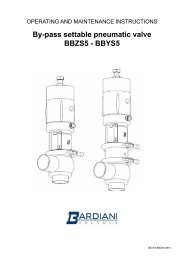
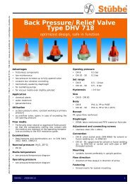
ZS5<br />
ZS5 ventil<br />
<strong>By</strong> <strong>Pass</strong><br />
Med sædeløft<br />
ZS5 ventilen har samme funktionsprincip<br />
som ZS1 ventilen. Muligheden for at forsyne<br />
cylinderen med trykluft unde fjederen,<br />
giver mulighed for CIP rengøring af<br />
sædet.<br />
ZS5 valve<br />
<strong>By</strong> <strong>Pass</strong><br />
With lift<br />
The ZS5 valve has the same working principle<br />
of the ZS1 valve. The possibility to<br />
supplying air in the cylinder under the<br />
spring allows the seat cleaning during<br />
the CIP operation.<br />
8
Tekniske data<br />
Technical details<br />
Ventildesign<br />
Ventilhuse er fremstillet af massivt rustfrit stål. Dette giver ventilhuse<br />
maksimal styrke til at undgå skævheder og spændinger, som kan opstå ved<br />
svejseprocesser.<br />
- Tilslutninger fra DN10 til DN80: DIN, SMS, IDF, BS(RJT), ISO, Clamp, Flange<br />
(andre tilslutninger på forespørgsel)<br />
- max. arbejdstryk: 10 bar (145 psi)<br />
- max. tæthedstryk: se tabel<br />
- min. arbejdstryk: Fuld vakuum<br />
- max. produkt temperatur: 140°C<br />
- min. produkt temperatur: -10°C<br />
- produktberørt materiale: AISI 316L (1.4404)<br />
- produktberørte pakninger (FDA): EPDM, FKM, MVQ(Silicone), NBR og<br />
P.T.F.E (andre materialer på forespørgsel)<br />
- produktberørt overfladeruhed: Ra0.8μm (andre overflader på forespørgsel).<br />
Pneumatisk aktuator specifikationer<br />
- lufttilslutninger 1/8” (BSP)<br />
- lufttryk fra 6bar (87psi) til 8bar (116psi)<br />
- materiale AISI 304L (1.4307)<br />
- pakningsmaterialer NBR<br />
Valve structure<br />
Valve bodies are made from solid stainless steel bar. This provides valve<br />
bodies with maximum strength avoiding any flaws and stresses that may<br />
occur from welding processes.<br />
-connections from DN10 to DN80: DIN, SMS, IDF, BS(RJT), ISO, Clamp, Flange<br />
(different connections upon request)<br />
-max. working pressure: 10 bar (145 psi)<br />
-max. seal pressure: see table<br />
-min. working pressure: full vacuum<br />
-max. product temperature: 140°C (284°F)<br />
-min. product temperature: -10°C (14°F)<br />
-material in contact with the product: AISI 316L (1.4404)<br />
-gaskets in contact with the product: (homologation FDA): EPDM, FKM,<br />
MVQ (Silicon), NBR and P.T.F.E. (other seals available upon request)<br />
-finish on surfaces in contact with the product: Ra0.8μm (other types of<br />
surface finish upon request).<br />
Pneumatic actuator specifications<br />
-air connectors 1/8” (BSP)<br />
-air pressure from 6 bar (87 psi) to 8 bar (116 psi)<br />
-material AISI 304L (1.4307)<br />
-gasket material NBR<br />
9
ZS5<br />
Hus med varmekappe<br />
Ventiler med varmekappe anvendes typisk<br />
for at modvirke størkning af smeltet produkt.<br />
Varmt vand der cirkulerer i kappen<br />
hjælper med at opretholde temperaturen<br />
og holde produktet flydende. Denne egenskab<br />
er også med til at forlænge pakningslevetiden.<br />
Anvendes typisk iforbindelse med<br />
produkter som voks og fedt.<br />
Jacket body<br />
A heated body jacket is typically used to<br />
avoid the solidification of melted products.<br />
Hot water circulating in the jacket helps<br />
to maintain the temperature and product<br />
fluidity. It also helps to extend gasket life.<br />
Typically used on fats and waxes.<br />
Reguleringskegle<br />
Kegler med regulerings karakteristik tillader<br />
en bedre lukke karakteristik.<br />
Parabolic shutter<br />
The parabolic profile of the shutter allows<br />
a better closing operation.<br />
Special varianter<br />
Different solutions<br />
Dampspærre<br />
En dampspærre er anbefalet iforbindelse<br />
med højhygiejniske applikationer såsom<br />
sterile og aseptiske processer eller<br />
højtemperatur sterilisering. Dampspærren<br />
minimerer risikoen for at produkt kommer<br />
i kontakt med den omgivende atmosfære.<br />
Dampspærren kan anvendes i vakum systemer,<br />
hvor kun en minimal mængde damp<br />
er tilladt at komme ind i ventilen.<br />
Steam barrier<br />
A steam barrier is recommended for very<br />
hygiene duties such as sterile, aseptic processing<br />
or high temperature sterilization.<br />
The steam barrier, placed between the<br />
valve body and the pneumatic actuator,<br />
minimises the risk of the product coming<br />
into contact with the external atmosphere.<br />
A steam barrier can be used on a vacuum<br />
system, in which case only a small amount<br />
of steam is allowed to enter the valve.<br />
Stålmembran<br />
Rustfri stålmembraner muliggør en sikker adskillelse mellem<br />
produktet og den omgivende atmosfære. Den er monteret<br />
mellem ventilhus og kegle. Den fungerer som en dampspærre,<br />
men kræver ikke damp.<br />
Fordelene omfatter større fleksibikitet og reducerede omkostninger.<br />
I relation til varmefølsomme produkter, forhindrer stålmembraner<br />
høje temperaturer, som er forbundet med dampspærre.<br />
Membranens rengøringsmuligheder gør den meget hygiejnisk.<br />
Metallic bellows<br />
Stainless steel metallic bellows allows a safe separation<br />
between the product and the external atmosphere. It is<br />
mounted between the valve body and the shutter. It acts<br />
like a steam barrier, but without requiring steam. Benefits<br />
include greater flexibility and reduced costs. On heat<br />
sensitive products, bellows avoid the high temperatures<br />
associated with steam barriers. Its clean features make it<br />
very hygiene.<br />
Dampspærre / Steam barrier<br />
• Kontinuerlig sterilitet<br />
Non stop sterility<br />
• Anlæg med risko for vakum<br />
Plant with negative pressures<br />
• Lav trykfald<br />
Lower friction loses<br />
• Nem servicering<br />
Easy maintenance<br />
Stålmembran / Metallic bellows<br />
• Ideel læsning for alle temperatur områder<br />
Ideal solution for all the temperatures<br />
• Ingen anvendelse af damp<br />
No use of steam or other devices<br />
• Anvendelig og billig<br />
Versatile and cheap<br />
• Nem servicering<br />
Easy maintenance<br />
Specielle optioner og varianter på forespørgsel<br />
På forespørgsel kan forskelligt tilbehør, og varianter leveres for hele ventilrækken. Det gælder også specielt udformede tilslutninger, dimensioner,<br />
eller andre skræddersyede løsninger. Teknisk rådgivning og analyse er selvfølgelig også en del af leverancen.<br />
Special options and variation on request<br />
On request most accessories are available for all sizes of valve and body configurations. Additionally special ports, diameters and other tailormade<br />
solutions are available. Bardiani Valve can also provide technical support, advice and feasibility analysis for other requests.<br />
10
Ventilhus konfigurationer<br />
Valve bodies configurations<br />
1.-2.-3..... eks. på rækkefølge for angivelse<br />
af tilslutninger ved forskellige<br />
typer og/eller dimensioner<br />
1st-2nd-3rd.... examples to read<br />
ends connections with different<br />
types and/or dimensions<br />
Anbefalet flowretning<br />
Recommended flow direction<br />
Normal lukket<br />
Normally closed<br />
Normal åben<br />
Normally open<br />
11
ZS5<br />
Dimensioner<br />
Dimensions<br />
S/S F/F DIN M/G DIN<br />
S/S DIN<br />
11850/2<br />
DN A G L Q Z Z A<br />
10 12x1 24,5 221 40 10 5 13x1,5<br />
15 18x1 28 221 40 10 5 19x1,5<br />
20 22x1,5 29,5 221 40 13 6 23x1,5<br />
25 28x1,5 46,5 255 60 13 6 29x1,5<br />
32 34x1,5 49,5 255 60 14 7 35x1,5<br />
40 40x1,5 52,5 255 60 13 6 41x1,5<br />
50 52x1,5 58,5 273 77 13 6 53x1,5<br />
65 70x2 72 307 100 15 7 70x2<br />
80 85x2 83 319 105 17 9 85x2<br />
S/S INCHES CLAMP F/F SMS F/F IDF F/F BS<br />
DN A G L Q Q Z Z Z<br />
1” 25,4x1,5 45 255 60 63 15 21,5 26,5<br />
1” 1/2 38,1x1,5 51,5 255 60 59,5 20 21,5 26,5<br />
2” 50,8x1,5 58 273 77 67,5 20 21,5 26,5<br />
2” 1/2 63,5x1,5 69,5 307 100 79 24 21,5 26,5<br />
3” 76,1x1,5 78,5 319 105 89,5 24 21,5 26,5<br />
Nomenklatur / Key<br />
S/S DIN<br />
F/F DIN<br />
M/G DIN<br />
Svejsning - Welding<br />
Nippel / Male<br />
Krave + omløber / Liner + nut<br />
S/S DIN 11850/2 Svejsning - Welding Din 11850/2<br />
CLAMP<br />
Clamp<br />
F/F SMS<br />
Nippel / Male SMS<br />
F/F IDF<br />
Nippel / Male IDF<br />
F/F BS<br />
Nippel / Male BS<br />
- På forespørgsel/On demand<br />
12
Maksimum sædetryk<br />
Maximum seal pressures<br />
DN<br />
10 / 15<br />
/ 20<br />
25 / 32<br />
/ 40<br />
FJEDER TYPE / SPRING TYPE<br />
bar<br />
A<br />
Blå<br />
Blue<br />
(d. 3.5)<br />
0.5 - 9 1 - 10<br />
FJEDER TYPE / SPRING TYPE<br />
bar<br />
CIL.52 CIL.83 CIL.52 CIL.83<br />
B<br />
Gul<br />
Yellow<br />
(d. 4)<br />
C<br />
Sort<br />
Black<br />
(d. 4.5)<br />
D<br />
Rød<br />
Red<br />
(dn 5)<br />
DN<br />
A<br />
Blå<br />
Blue<br />
(d. 3.5)<br />
B<br />
Gul<br />
Yellow<br />
(d. 4)<br />
C<br />
Sort<br />
Black<br />
(d. 4.5)<br />
D<br />
Rød<br />
Red<br />
(d. 5)<br />
0.5 - 2 1 - 4 1 - 5 1 - 10 1” 1”1/2 0.5 - 2 1 - 4 1 - 5 1 - 10<br />
50 0.5 - 2.5 1 - 3 1 - 6 2” 0.5 - 2.5 1 - 3 1 - 6<br />
65 0.5 - 1.5 1 - 3.5 2” 1/2 0.5 - 1.5 1 - 3.5<br />
80 0.5 - 1 1 - 2 3” 0.5 - 1 1 - 2<br />
DN<br />
10 / 15<br />
/ 20<br />
25 / 32<br />
/ 40<br />
FJEDER TYPE / SPRING TYPE<br />
psi<br />
A<br />
Blå<br />
Blue<br />
(d. 3.5)<br />
7.5 - 135 15 - 150<br />
FJEDER TYPE / SPRING TYPE<br />
psi<br />
CIL.52 CIL.83 CIL.52 CIL.83<br />
B<br />
Gul<br />
Yellow<br />
(d. 4)<br />
C<br />
Sort<br />
Black<br />
(d. 4.5)<br />
D<br />
Rød<br />
Red<br />
(d. 5)<br />
DN<br />
A<br />
Blå<br />
Blue<br />
(d. 3.5)<br />
B<br />
Gul<br />
Yellow<br />
(d. 4)<br />
C<br />
Sort<br />
Black<br />
(d. 4.5)<br />
D<br />
Rød<br />
Red<br />
(d. 5)<br />
7.5 - 30 15 - 60 15 - 75 15 - 150 1” 1”1/2 7.5 - 30 15 - 60 15 - 75 15 - 150<br />
50 7.5 - 37.5 15 - 45 15 - 90 2” 7.5 - 37.5 15 - 45 15 - 90<br />
65 2.25 - 22.5 7.5 - 52.5 2” 1/2 7.5 - 22.5 7.5 - 52.5<br />
80 7.5 - 25.5 15 - 30 3” 7.5 - 25.5 15 - 30<br />
13
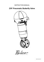
ZSA<br />
ZSA Ventil<br />
<strong>By</strong> <strong>Pass</strong><br />
Pneumatisk<br />
ZSA repræsenterer by-pass seriens<br />
udvikling. Holdetrykket på keglen forsynes<br />
ved hjælp af lufttryk i den pneumatiske<br />
cylinder. Dimensioneringen af den<br />
pneumatiske cylinder afhænger af produkt<br />
detaljer og arbejdstryk.<br />
ZSA valve<br />
<strong>By</strong> <strong>Pass</strong><br />
Pneumatic<br />
ZSA valve represents the by-pass range<br />
evolution. The seat load is provided by<br />
the air pressure in the pneumatic actuator.<br />
The pneumatic dimensioning depends<br />
from the product details and from the<br />
working pressure.<br />
14
Tekniske data<br />
Technical details<br />
Ventildesign<br />
Ventilhuse er fremstillet af massivt rustfrit stål. Dette giver ventilhuse<br />
maksimal styrke til at undgå skævheder og spændinger, som kan opstå ved<br />
svejseprocesser.<br />
- Tilslutninger fra DN25 til DN100: DIN, SMS, IDF, BS(RJT), ISO, Clamp, Flange<br />
(andre tilslutninger på forespørgsel)<br />
- max. arbejdstryk: 10 bar (145 psi)<br />
- max. tæthedstryk: se tabel<br />
- min. arbejdstryk: Fuld vakuum<br />
- max. produkt temperatur: 140°C<br />
- min. produkt temperatur: -10°C<br />
- produktberørt materiale: AISI 316L (1.4404)<br />
- produktberørte pakninger (FDA): EPDM, FKM, MVQ(Silicone), NBR og<br />
P.T.F.E (andre materialer på forespørgsel)<br />
- produktberørt overfladeruhed: Ra0.8μm (andre overflader på forespørgsel).<br />
Pneumatisk aktuator specifikationer<br />
- lufttilslutninger 1/8” (BSP)<br />
- lufttryk fra 6bar (87psi) til 8bar (116psi)<br />
- materiale AISI 304L (1.4307)<br />
- pakningsmaterialer NBR<br />
Valve structure<br />
Valve bodies are made from solid stainless steel bar. This provides valve<br />
bodies with maximum strength avoiding any flaws and stresses that may<br />
occur from welding processes.<br />
-connections from DN25 to DN100: DIN, SMS, IDF, BS(RJT), ISO, Clamp,<br />
Flange (different connections upon request)<br />
-max. working pressure: 10 bar (145 psi)<br />
-max. seal pressure: see table<br />
-min. working pressure: full vacuum<br />
-max. product temperature: 140°C (284°F)<br />
-min. product temperature: -10°C (14°F)<br />
-material in contact with the product: AISI 316L (1.4404)<br />
-gaskets in contact with the product: (homologation FDA): EPDM, FKM,<br />
MVQ (Silicon), NBR and P.T.F.E. (other seals available upon request)<br />
-finish on surfaces in contact with the product: Ra0.8μm (other types of<br />
surface finish upon request).<br />
Pneumatic actuator specifications<br />
-air connectors 1/8” (BSP)<br />
-air pressure from 6 bar (87 psi) to 8 bar (116 psi)<br />
-material AISI 304L (1.4307)<br />
-gasket material NBR<br />
15
ZSA<br />
Special varianter<br />
Different solutions<br />
Dampspærre<br />
En dampspærre er anbefalet iforbindelse med<br />
højhygiejniske applikationer såsom sterile og<br />
aseptiske processer eller højtemperatur sterilisering.<br />
Dampspærren minimerer risikoen for<br />
at produkt kommer i kontakt med den omgivende<br />
atmosfære. Dampspærre kan anvendes<br />
i vakum systemer, hvor kun en minimal mængde<br />
damp er tilladt at komme ind i ventilen.<br />
Steam barrier<br />
A steam barrier is recommended for very hygiene<br />
duties such as sterile, aseptic processing<br />
or high temperature sterilization. The steam<br />
barrier, placed between the valve body and the<br />
pneumatic actuator, minimises the risk of the<br />
product coming into contact with the external<br />
atmosphere. A steam barrier can be used on a vacuum<br />
system, in which case only a small amount<br />
of steam allowed to enter the valve.<br />
Hus med varmekappe<br />
Ventiler med varmekappe anvendes typisk<br />
for at modvirke størkning af smeltet produkt.<br />
Varmt vand der cirkulerer i kappen<br />
hjælper med at opretholde temperaturen<br />
og holde produktet flydende. Denne egenskab<br />
er også med til at forlænge pakningslevetiden.<br />
Anvendes typisk iforbindelse med<br />
produkter som voks og fedt.<br />
Jacket body<br />
A heated body jacket is typically used to<br />
avoid the solidification of melted products.<br />
Hot water circulating in the jacket helps<br />
to maintain the temperature and product<br />
fluidity. It also helps to extend gasket life.<br />
Typically used on fats and waxes.<br />
Dampspærre / Steam barrier<br />
• Kontinuerlig sterilitet<br />
Non stop sterility<br />
• Anlæg med risko for vakum<br />
Plant with negative pressures<br />
• Lav trykfald<br />
Lower friction loses<br />
• Nem servicering<br />
Easy maintenance<br />
Reguleringskegle<br />
Kegler med regulerings karakteristik tillader<br />
en bedre lukke karakteristik.<br />
Parabolic shutter<br />
The parabolic profile of the shutter allows<br />
a better closing operation.<br />
16
Stålmembran<br />
Rustfri stålmembraner muliggør en sikker<br />
adskillelse mellem produktet og den omgivende<br />
atmosfære. Den er monteret mellem ventilhus<br />
og kegle. Den fungerer som en dampspærre, men<br />
kræver ikke damp.<br />
Fordelene omfatter større fleksibikitet og reducerede<br />
omkostninger.<br />
I relation til varmefølsomme produkter, forhindrer<br />
stålmembraner høje temperaturer, som er<br />
forbundet med dampspærre.<br />
Membranens rengøringsmuligheder gør den meget<br />
hygiejnisk.<br />
Metallic bellows<br />
Stainless steel metallic bellows allows a safe<br />
separation between the product and the external<br />
atmosphere. It is mounted between the<br />
valve body and the shutter. It acts like a steam<br />
barrier, but without requiring steam. Benefits<br />
include greater flexibility and reduced costs.<br />
On heat sensitive products, bellows avoid the<br />
high temperatures associated with steam barriers.<br />
Its clean features make it very hygiene.<br />
Stålmembran / Metallic bellows<br />
• Ideel til alle temperaturområder<br />
Ideal solution for all the temperatures<br />
• Ingen anvendelse af damp<br />
No use of steam or other devices<br />
• Anvendelig og billig<br />
Versatile and cheap<br />
• Nem servicering<br />
Easy maintenacne<br />
Tryk regulator +<br />
manometer<br />
Tryk regulatoren er en god løsning for<br />
ZSA by-pass ventilen. Med denne enhed<br />
er det muligt at regulere lufttrykket i<br />
den pnuematiske cylinder, for at indstille<br />
sædetrykket. På regulatorens manometer<br />
kan forsyningstrykket aflæses.<br />
Pressure regulator +<br />
Manometer<br />
The pressure regulator is a good solution<br />
for ZSA by-pass valve. With this device,<br />
it is possible to regulate the air pressure<br />
into the pneumatic actuator, modificating<br />
the seal pressure. Fitted with the pressure<br />
regulator, the manometer shows<br />
the air supplying.<br />
Specielle optioner og varianter på forespørgsel<br />
På forespørgsel kan forskelligt tilbehør, og varianter leveres for hele ventilrækken. Det gælder også specielt udformede tilslutninger, dimensioner,<br />
eller andre skræddersyede løsninger. Teknisk rådgivning og analyse er selvfølgelig også en del af leverancen.<br />
Special options and variation on request<br />
On request most accessories are available for all sizes of valve and body configurations. Additionally special ports, diameters and other tailormade<br />
solutions are available. Bardiani Valve can also provide technical support, advice and feasibility analysis for other requests.<br />
17
ZSA<br />
Ventilhus konfigurationer<br />
Valve bodies configurations<br />
1.-2.-3..... eks. på rækkefølge for angivelse<br />
af tilslutninger ved forskellige<br />
typer og/eller dimensioner<br />
1st-2nd-3rd.... examples to read<br />
ends connections with different<br />
types and/or dimensions<br />
Anbefalet flowretning<br />
Recommended flow direction<br />
Normal lukket<br />
Normally closed<br />
Normal åben<br />
Normally open<br />
18
Dimensioner<br />
Dimensions<br />
S/S DIN<br />
F/F DIN M/G DIN<br />
S/S DIN<br />
11850/2<br />
DN A F G Q Z Z A<br />
25 28x1,5 94 46,5 60 13 6 29x1,5<br />
32 34x1,5 94 49,5 60 14 7 35x1,5<br />
40 40x1,5 94 52,5 60 13 6 41x1,5<br />
50 52x1,5 112 58,5 77 13 6 53x1,5<br />
65 70x2 133 72 100 15 7 70x2<br />
80 85x2 156,5 83 105 17 9 85x2<br />
100 101,6x2 179 95 120 19 9 104x2<br />
S/S INCHES CLAMP F/F SMS F/F IDF F/F BS<br />
DN A F G Q Q Z Z Z<br />
1” 25,4x1,5 94 45 60 63 15 21,5 26,5<br />
1” 1/2 38,1x1,5 94 51,5 60 59,5 20 21,5 26,5<br />
2” 50,8x1,5 112 58 77 67,5 20 21,5 26,5<br />
2” 1/2 63,5x1,5 133 69.5 100 79 24 21,5 26,5<br />
3” 76,1x2 156,5 78,5 105 89,5 24 21,5 26,5<br />
4” 101,6x2 179 95 120 93 25 21,5 26,5<br />
CILINDRO / CYLINDER<br />
d. 52 d. 83 d. 95 d. 108 d. 130<br />
D 60 89 101,6 114 140<br />
L 110 147 147 147 147<br />
Nomenklatur / Key<br />
S/S DIN<br />
Svejse - Welding<br />
F/F DIN<br />
Nippel / Male<br />
M/G DIN Krave + omløber / Liner + nut<br />
S/S DIN 11850/2 Svejse - Welding Din 11850/2<br />
CLAMP<br />
Clamp<br />
F/F SMS<br />
Nippel / Male SMS<br />
F/F IDF<br />
Nippel / Male IDF<br />
F/F BS<br />
Nippel / Male BS<br />
- På forespørgsel/On demand<br />
19
ZSA<br />
Maksimum sædetryk<br />
Maximum seal pressures<br />
DN<br />
CIL. 52<br />
bar<br />
CIL. 83<br />
bar<br />
CIL. 95<br />
bar<br />
CIL. 108<br />
bar<br />
CIL. 130<br />
bar<br />
1” - 25<br />
32<br />
1”1/2 - 40<br />
7 10<br />
2” - 50 5 10<br />
2” 1/2- 65 2 7 9 10<br />
3”- 80 1 4 6 8 10<br />
4” - 100 0,5 2,5 4 5 8<br />
DN<br />
CIL. 52<br />
psi<br />
CIL. 83<br />
psi<br />
CIL. 95<br />
psi<br />
CIL. 108<br />
psi<br />
CIL. 130<br />
psi<br />
1” - 25<br />
32<br />
1”1/2 - 40<br />
105 150<br />
2” - 50 75 150<br />
2” 1/2- 65 30 105 135 150<br />
3”- 80 15 60 90 120 150<br />
4” - 100 7.5 37.5 60 75 120<br />
20
ZS Range<br />
Vægt (KG)<br />
Weights (KG)<br />
<strong>By</strong>-pass <strong>ventiler</strong> - <strong>By</strong>-pass <strong>valves</strong><br />
DN ZS1 ZS5 Cil.52 ZS5 Cil.83 ZSA Cil.52 ZSA Cil. 83<br />
15 1,7 - - - -<br />
20 1,7 3.5 4 2 -<br />
25 2,2 3.5 4 3 3.7<br />
32 2,2 3.25 4 3 3.6<br />
40 2,2 3.2 4 3 3.6<br />
50 2,4 4 4.5 4 4.5<br />
65 5,3 5 5.7 5.6 5.8<br />
80 5,8 7 6.8 6.2 7<br />
100 7,9 8.4 - - -<br />
Bemærk<br />
- Ovenstående vægte refererer til standard konfigurationer:<br />
svejseender, L-port huse.<br />
- Ovenstående vægte er kun indikative.<br />
Take note<br />
- Above weights refer to standard configurations:<br />
welding ends, L-port valve bodies.<br />
- Above weights have pure indicative values.<br />
21
Raccomandazioni<br />
Disclaimer<br />
1. Tutte le affermazioni, le indicazioni e le notizie<br />
tecniche qui riportate sono basate sui dati di prove<br />
che riteniamo attendibili, ma non riferibili ad ogni<br />
possibile utilizzo del prodotto. Dal momento che le<br />
condizioni d’uso e di applicazione sono al di fuori del<br />
nostro controllo, l’Acquirente deve preventivamente<br />
accertare l’idoneità del prodotto all’uso al quale<br />
intende destinarlo, assumendo ogni rischio e<br />
responsabilità derivante dall’uso stesso. Bardiani<br />
Valvole S.p.A. non si assume responsabilità per alcun<br />
incidente, perdita o danno, diretto o consequenziale<br />
derivante dall’uso o dall’impossibilità d’uso del<br />
prodotto. Nessuno è autorizzato a concedere garanzie<br />
maggiori o diverse da quelle qui riportate.<br />
2. Raccomandiamo ai nostri clienti di consultare sempre i<br />
nostri collaboratori tecnici-commerciali per richiedere<br />
informazioni specifiche in merito alle caratteristiche<br />
tecniche dei nostri prodotti.<br />
3. Le raffigurazioni, tutte di valore generale e non<br />
vincolante, possono non corrispondere alle reali<br />
condizioni dei prodotti.<br />
4. Bardiani Valvole S.p.A. si riserva in qualsiasi momento<br />
e senza preavviso di modificare e/o aggiornare i dati,<br />
i disegni e le informazioni riportate nel presente<br />
documento<br />
5. Quanto riportato sulla presente pubblicazione si<br />
riferisce a prodotti di nostra normale produzione e<br />
non può in alcun caso essere un riferimento di base<br />
per prodotti eseguiti su specifiche richieste.<br />
6. Bardiani Valvole S.p.A. non è responsabile per i vizi<br />
e/o i difetti derivanti da installazione del prodotto<br />
non in conformità a quanto indicato nel “Manuale di<br />
istruzioni uso e manutenzione” o comunque derivanti<br />
da installazione non corretta o impropria o da un uso<br />
non corretto e/o improprio del prodotto.<br />
7. Bardiani Valvole S.p.A. non è responsabile per vizi<br />
e/o difetti del prodotto derivanti da un trasporto<br />
non corretto e/o derivanti da una impropria e/o<br />
non idonea conservazione e/o manutenzione dello<br />
stesso.<br />
8. Bardiani Valvole S.p.A. non è responsabile per difetti<br />
e/o vizi del prodotto dovuti a manomissioni e/o a<br />
interventi effettuati da personale non qualificato<br />
professionalmente, così come non è responsabile per<br />
i danni provocati da urti, ammaccamenti, incuria,<br />
negligenza ed in genere cause non imputabili a difetti<br />
di costruzione, fabbricazione e difetti di materiale.<br />
22<br />
1. All the statements, indications and technical data<br />
listed in this document are based on technical tests<br />
carried out by Bardiani Valvole S.p.A.. However<br />
accurate and reliable, such tests do not reflect all<br />
possible circumstances under which the products<br />
may be used. It is therefore advisable that the<br />
Buyer should always ascertain the suitability of the<br />
product in its application. The Buyer will be entirely<br />
liable for all risks and damages incurred by said<br />
products. Bardiani Valvole S.p.A. are not liable for<br />
any accident, loss or damage incurred, whether they<br />
be directly or indirectly caused by the use or misuse<br />
of the products. No further guarantees other than<br />
those stated in this document shall be granted.<br />
2. All our customers are advised to consult our<br />
technicians as well as our offices who will supply all<br />
information pertaining the technical characteristics<br />
of our products.<br />
3. The pictures contained in this document are<br />
intended to be general representations. They are<br />
not to be intended either legally binding or detailed<br />
representations of our products.<br />
4. Bardiani Valvole S.p.A. reserve the right at any time<br />
and with no further notice to amend and up-date<br />
the technical data, designs and the information<br />
contained in this document.<br />
5. The data and statements listed in this document only<br />
refer to our standard products. They do not apply<br />
in any case to any tailor-made products that might<br />
have been purchased by the customers.<br />
6. Bardiani Valvole S.p.A. are not liable for any defects<br />
or faults resulting from the incorrect installation of<br />
their products. Such installation is to be carried out<br />
in full compliance with the instructions contained<br />
in the “Manual of Instructions for the Use and<br />
Maintenance of the Product”. Bardiani Valvole S.p.A.<br />
are not liable for any defects or faults resulting from<br />
the incorrect use of their products.<br />
7. Bardiani Valvole S.p.A. are not liable for any<br />
defects or faults resulting from the incorrect<br />
transportation and/or incorrect storage and/or<br />
incorrect maintenance of their products.<br />
8. Bardiani Valvole S.p.A. cannot accept any liability<br />
for any faults or damages deriving from mishandling<br />
of the products and/or interventions carried out<br />
by unqualified personnel. No liability is accepted<br />
for damages caused by hits, dents, carelessness,<br />
negligence or any other any acts that cannot be<br />
considered as construction faults or faults related<br />
to the materials used in production.
DK-CAT-SIC-1005<br />
23
Stampa Digigraph PR<br />
VISUAL SERVICE NOCETO<br />
Bardiani Valvole s.p.a. via G. di Vittorio, 50-52, 43045 Fornovo di Taro (PR) Italy<br />
Tel +39.0525.400044 Fax +39.0525.3408<br />
e-mail: bardiani@bardiani.com www.bardiani.com