Subject Page Expansion Tank and Brake Fluid Level ... - bmwtech.ru
Subject Page Expansion Tank and Brake Fluid Level ... - bmwtech.ru
Subject Page Expansion Tank and Brake Fluid Level ... - bmwtech.ru

You also want an ePaper? Increase the reach of your titles
YUMPU automatically turns print PDFs into web optimized ePapers that Google loves.
<strong>Subject</strong><br />
<strong>Page</strong><br />
<strong>Expansion</strong> <strong>Tank</strong> <strong>and</strong> <strong>Brake</strong> <strong>Fluid</strong> <strong>Level</strong> Switch. . . . . . . . . . .30<br />
<strong>Brake</strong> Pressure Sensors. . . . . . . . . . . . . . . . . . . . . . . . . . 31<br />
Wheel Speed Sensors. . . . . . . . . . . . . . . . . . . . . . . . . . . .32<br />
Rotation Rate Sensor. . . . . . . . . . . . . . . . . . . . . . . . . . . . 35<br />
Steering Angle Sensor. . . . . . . . . . . . . . . . . . . . . . . . . . . .36<br />
Transverse Acceleration Sensor. . . . . . . . . . . . . . . . . . . . . 37<br />
DSC Button. . . . . . . . . . . . . . . . . . . . . . . . . . . . . . . . . . . 38<br />
Inst<strong>ru</strong>ment Cluster Warning Indicators. . . . . . . . . . . . . . . . 39<br />
Principle of Operation. . . . . . . . . . . . . . . . . . . . . . . . . . . . . . . . . 40<br />
ABS. . . . . . . . . . . . . . . . . . . . . . . . . . . . . . . . . . . . . . . . .40<br />
ASC. . . . . . . . . . . . . . . . . . . . . . . . . . . . . . . . . . . . . . . . .44<br />
DSC. . . . . . . . . . . . . . . . . . . . . . . . . . . . . . . . . . . . . . . . .48<br />
Workshop Hints. . . . . . . . . . . . . . . . . . . . . . . . . . . . . . . . . . . . . 55<br />
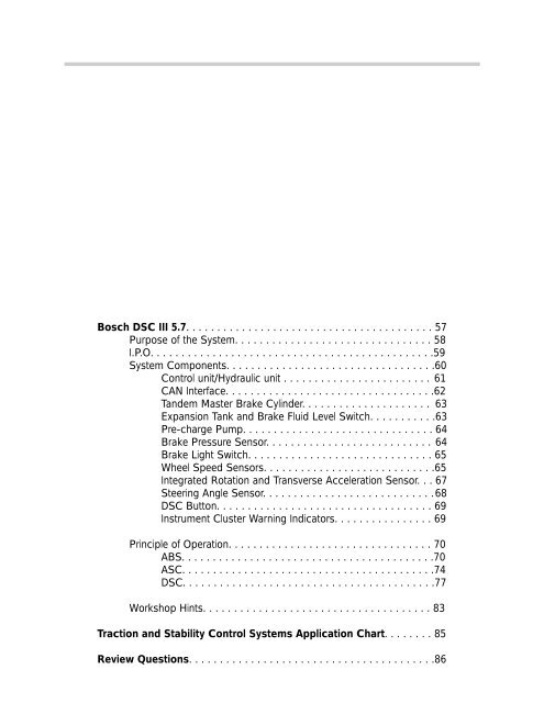
Bosch DSC III 5.7. . . . . . . . . . . . . . . . . . . . . . . . . . . . . . . . . . . . . . . . 57<br />
Purpose of the System. . . . . . . . . . . . . . . . . . . . . . . . . . . . . . . . 58<br />
I.P.O. . . . . . . . . . . . . . . . . . . . . . . . . . . . . . . . . . . . . . . . . . . . . .59<br />
System Components. . . . . . . . . . . . . . . . . . . . . . . . . . . . . . . . . .60<br />
Control unit/Hydraulic unit . . . . . . . . . . . . . . . . . . . . . . . . 61<br />
CAN Interface. . . . . . . . . . . . . . . . . . . . . . . . . . . . . . . . . .62<br />
T<strong>and</strong>em Master <strong>Brake</strong> Cylinder. . . . . . . . . . . . . . . . . . . . . 63<br />
<strong>Expansion</strong> <strong>Tank</strong> <strong>and</strong> <strong>Brake</strong> <strong>Fluid</strong> <strong>Level</strong> Switch. . . . . . . . . . .63<br />
Pre-charge Pump. . . . . . . . . . . . . . . . . . . . . . . . . . . . . . . 64<br />
<strong>Brake</strong> Pressure Sensor. . . . . . . . . . . . . . . . . . . . . . . . . . . 64<br />
<strong>Brake</strong> Light Switch. . . . . . . . . . . . . . . . . . . . . . . . . . . . . . 65<br />
Wheel Speed Sensors. . . . . . . . . . . . . . . . . . . . . . . . . . . .65<br />
Integrated Rotation <strong>and</strong> Transverse Acceleration Sensor. . . 67<br />
Steering Angle Sensor. . . . . . . . . . . . . . . . . . . . . . . . . . . .68<br />
DSC Button. . . . . . . . . . . . . . . . . . . . . . . . . . . . . . . . . . . 69<br />
Inst<strong>ru</strong>ment Cluster Warning Indicators. . . . . . . . . . . . . . . . 69<br />
Principle of Operation. . . . . . . . . . . . . . . . . . . . . . . . . . . . . . . . . 70<br />
ABS. . . . . . . . . . . . . . . . . . . . . . . . . . . . . . . . . . . . . . . . .70<br />
ASC. . . . . . . . . . . . . . . . . . . . . . . . . . . . . . . . . . . . . . . . .74<br />
DSC. . . . . . . . . . . . . . . . . . . . . . . . . . . . . . . . . . . . . . . . .77<br />
Workshop Hints. . . . . . . . . . . . . . . . . . . . . . . . . . . . . . . . . . . . . 83<br />
Traction <strong>and</strong> Stability Control Systems Application Chart. . . . . . . . 85<br />
Review Questions. . . . . . . . . . . . . . . . . . . . . . . . . . . . . . . . . . . . . . . .86
BOSCH DSC III 5.7<br />
Model: E46/16<br />
Production Date: 330xi 6/00, 325xi 9/00<br />
Objectives<br />
After completing this module you should be able to:<br />
• Identify functions of the DSC 5.7 that are specific to All-Wheel Drive.<br />
• Identify the components used in the system.<br />
• Underst<strong>and</strong> the operating principles of ABS, ASC <strong>and</strong> DSC.<br />
57<br />
E46 Traction <strong>and</strong> Stability Control Systems
Purpose of the System<br />
The Bosch DSC III 5.7 is used in the E46/16 in place of the DSC III MK 60 used on 2wd<br />
vehicles. The DSC system is the same as used in the E53. HDC is not a feature on 2001<br />
Xi models.<br />
Functions that are specific for the All-Wheel Drive system are:<br />
• Modified ABS function.<br />
• ASC+T (All-Wheel Drive version).<br />
• Four wheel ADB function.<br />
The Bosch DSC III 5.7 system is designed to maintain the vehicle’s stability<br />
during:<br />
• ABS braking regulation<br />
• ASC+T traction control<br />
• DSC for oversteer <strong>and</strong> understeer control<br />
Additional features are also programmed into the control module to enhance driver safety<br />
<strong>and</strong> comfort. These features are:<br />
• CBC Corner <strong>Brake</strong> Control<br />
• EBV Electronic <strong>Brake</strong> Proportioning<br />
• MSR Engine Drag Torque Reduction<br />
• DBS Dynamic <strong>Brake</strong> System<br />
58<br />
E46 Traction <strong>and</strong> Stability Control Systems
MoDiC<br />
HW:00<br />
HW: 0<br />
0<br />
12<br />
UNLEADED GASOLINE ONLY<br />
SERVICE<br />
ENGINE<br />
SOON<br />
11<br />
EML<br />
100 120 140 160<br />
80<br />
180<br />
60<br />
200<br />
40<br />
220<br />
20<br />
240<br />
km/h<br />
MPH<br />
!<br />
1/min<br />
x1000<br />
miles BRAKE<br />
ABS ABS<br />
KL 30<br />
ABS LAMP<br />
KL 15<br />
DME<br />
MAIN<br />
RELAY<br />
KL 15<br />
ABS<br />
DSC<br />
DSC SWITCH<br />
POWER SUPPLY<br />
POWER SUPPLY<br />
LF<br />
WHEEL<br />
PUMP<br />
RF<br />
INLET ( 4X)<br />
SPEED<br />
OUTLET (4X)<br />
LR<br />
SENSORS<br />
CHANGEOVER (2x)<br />
PRE-LOAD (2x)<br />
DSCIII 5.7<br />
HYDRAULIC<br />
UNIT<br />
RR<br />
DSC III<br />
5.7<br />
BRAKE<br />
PRESSURE<br />
SENSOR<br />
BRAKE PRESSURE<br />
SIGNAL<br />
42Pin<br />
POWER SUPPLY<br />
GROUND<br />
SENSOR TEST<br />
219<br />
078<br />
0 265 005 215<br />
34 52 1 165 292<br />
98300<br />
0000083<br />
Made in Germany<br />
B<br />
BOSCH<br />
ROTATION<br />
RATE SENSOR<br />
BOSCH<br />
B<br />
0 265 005 215<br />
34 52 1 165 292<br />
98300<br />
0000083<br />
219<br />
Made in Germany 078<br />
REFERENCE VOLTAGE<br />
SIGNAL VOLTAGE<br />
SIGNAL VOLTAGE<br />
PRE-CHARGE<br />
PUMP<br />
CONTROL<br />
CAN<br />
P<br />
BMW 37 14 1 093 8 2<br />
STEERING ANGLE<br />
SENSOR<br />
ROTATION<br />
RATE SENSOR<br />
+<br />
1 2 3 4 5<br />
AGS<br />
1 2 3 4 5<br />
DME<br />
40<br />
20<br />
80<br />
60 100<br />
120<br />
140<br />
2<br />
1<br />
0<br />
3 4<br />
50 30 20 15<br />
12<br />
5<br />
6<br />
7<br />
BRAKE LIGHT<br />
SWITCH<br />
X<br />
RIGHT REAR<br />
MK III<br />
!<br />
BRAKE<br />
PARK BRAKE<br />
SWITCH<br />
TO LSZ<br />
LEFT REAR<br />
PROCESSED WHEEL SPEED<br />
DSC LAMP<br />
GENERAL BRAKE<br />
WARNING LAMP<br />
SPLICE TO KOMBI<br />
BMW DIS<br />
BMW DIS<br />
DIAGNOSIS<br />
BRAKE FLUID<br />
LEVEL<br />
BMW DIS<br />
59<br />
E46 Traction <strong>and</strong> Stability Control Systems
System Components<br />
The Bosch DSC III 5.7 for the E46/16 consists of the following components:<br />
• Integrated Control Unit/Hydraulic Unit with CAN Interface<br />
• T<strong>and</strong>em <strong>Brake</strong> Master Cylinder<br />
• <strong>Brake</strong> <strong>Fluid</strong> <strong>Expansion</strong> <strong>Tank</strong> with Integrated <strong>Level</strong> Sensor<br />
• Pre-Charge Pump<br />
• <strong>Brake</strong> Pressure Sensor (Located on Hydraulic Unit)<br />
• <strong>Brake</strong> Light Switch<br />
• 4 Wheel Speed Sensors (Active)<br />
• Rotation Rate/Transverse Acceleration Integrated Sensor<br />
• Steering Angle Sensor<br />
• DSC Button<br />
• Inst<strong>ru</strong>ment Cluster Warning Indicators<br />
• H<strong>and</strong>brake Switch<br />
• Wiring Harness<br />
60<br />
E46 Traction <strong>and</strong> Stability Control Systems
Control Unit/Hydraulic Unit<br />
The Bosch DSC III 5.7 control unit/hydraulic<br />
unit is located inside the engine compartment<br />
on the right h<strong>and</strong> side.<br />
Both the control unit <strong>and</strong> the hydraulic unit<br />
are replaceable as separate components.<br />
All processing functions for ABS, ASC <strong>and</strong><br />
DSC are performed in the combined control/hydraulic<br />
unit. The control unit is also<br />
responsible for processing the wheel speed<br />
signals <strong>and</strong> providing them to other control<br />
units.<br />
Bosch DSC III 5.7<br />
Hydraulic Unit<br />
LOW BRAKE<br />
FLUID SIGNAL<br />
RESERVOIR<br />
MASTER<br />
CYLINDER<br />
DSC III 5.7<br />
HYDRAULIC UNIT<br />
REAR AXLE BRAKE CIRCUITS<br />
INTAKE<br />
VALVE<br />
CHARGE<br />
PRESSURE<br />
SIGNAL<br />
PUMP<br />
MOTOR<br />
CHANGEOVER<br />
VALVE<br />
INTAKE<br />
VALVE<br />
CHARGE<br />
PUMP<br />
P<br />
FRONT AXLE BRAKE CIRCUITS<br />
CHANGEOVER<br />
VALVE<br />
LOW PRESSURE<br />
ACCUMULATOR<br />
P<br />
PUMP<br />
LOW PRESSURE<br />
ACCUMULATOR<br />
P<br />
PUMP<br />
INLET<br />
VALVE<br />
OUTLET<br />
VALVE<br />
OUTLET<br />
VALVE<br />
INLET<br />
VALVE<br />
INLET<br />
VALVE<br />
OUTLET<br />
VALVE<br />
OUTLET<br />
VALVE<br />
INLET<br />
VALVE<br />
LEFT<br />
REAR<br />
BRAKE<br />
RIGHT<br />
REAR<br />
BRAKE<br />
The hydraulic unit consist of an aluminum block containing 12 solenoid valves, 2 pressure<br />
accumulators <strong>and</strong> the return pump.<br />
• 4 inlet solenoid valves (N/O) • 2 changeover solenoid valves (N/O)<br />
• 4 outlet solenoid valves (N/C) • 2 intake solenoid valves (N/C)<br />
The solenoid valving ensures that normal braking is possible in the event of a defective<br />
control unit.<br />
LEFT<br />
FRONT<br />
BRAKE<br />
RIGHT<br />
FRONT<br />
BRAKE<br />
Note: N/O= Normally Open, N/C=Normally Closed<br />
61<br />
E46 Traction <strong>and</strong> Stability Control Systems
CAN Interface<br />
The Bosch DSC III 5.7 is connected to the CAN bus for communication with the AGS, DME<br />
control module, Steering Angle Sensor <strong>and</strong> the Inst<strong>ru</strong>ment Cluster.<br />
Using the CAN bus, all of the connected modules can receive information or send<br />
comm<strong>and</strong>s.<br />
Communication with the DSC III 5.7 includes:<br />
• DME - The DME sends current engine torque. DSC comm<strong>and</strong>s the DME to reduce<br />
(ASC/DSC) or raise (MSR) engine torque.<br />
• AGS - The DSC comm<strong>and</strong>s the AGS to suppress shifts during regulation.<br />
• LEW - The DSC receives steering angle information.<br />
• KOMBI - The DSC comm<strong>and</strong>s the inst<strong>ru</strong>ment cluster to activate or deactivate the<br />
warning lamps.<br />
• All four wheels speed signals are sent over the CAN bus for use by other modules.<br />
INSTRUMENT<br />
CLUSTER<br />
GS 20<br />
MS 43.0<br />
12<br />
0<br />
11<br />
UNLEADED GASOLINE ONLY<br />
80<br />
60 100<br />
100 120 140 160<br />
80<br />
180<br />
40<br />
120<br />
60<br />
200<br />
40<br />
220<br />
20 20<br />
240 140<br />
km/h<br />
2<br />
1<br />
0<br />
3 4<br />
1/min<br />
x1000<br />
50 3020 15<br />
12<br />
5<br />
6<br />
7<br />
MPH<br />
1 2 3 4 5<br />
Mmiles<br />
CAN BUS<br />
SPLICE CONNECTIONS<br />
FOR TWISTED PAIR CAN<br />
LEW<br />
BOSCH<br />
62<br />
E46 Traction <strong>and</strong> Stability Control Systems<br />
DSC III 5.7
T<strong>and</strong>em <strong>Brake</strong> Master Cylinder<br />
The DSC III 5.7 system uses a t<strong>and</strong>em brake master cylinder fitted with central valves as<br />
other DSC master cylinders. The central valves allow fluid to be drawn through the master<br />
cylinder during ASC <strong>and</strong> DSC regulation. The hydraulic circuit is split front/rear.<br />
An orifice for pre-charge pressure is fitted into the brake front axle circuit <strong>and</strong> is connected<br />
to the pre-charge pump via a steel braided flexible line.<br />
<strong>Brake</strong> <strong>Fluid</strong> <strong>Expansion</strong> <strong>Tank</strong> with Integrated <strong>Level</strong> Switch<br />
The brake fluid expansion tank<br />
has internal baffles that reduce<br />
foaming during return pump<br />
operation.<br />
The expansion tank includes a<br />
pick-up tube for clutch master<br />
cylinder fluid supply <strong>and</strong> a<br />
second lower one for the charge<br />
pump supply.<br />
The brake fluid level switch is<br />
incorporated into the tank. The<br />
switch is a reed contact switch. If<br />
the brake fluid is at a sufficient<br />
level, the switch is closed <strong>and</strong><br />
switched to ground.<br />
If the fluid level drops below a specified level , the reed contacts open <strong>and</strong> the DSC<br />
responds by switching off the ASC/DSC functions.<br />
Normal braking <strong>and</strong> ABS operation is unaffected.<br />
63<br />
E46 Traction <strong>and</strong> Stability Control Systems
Pre-Charge Pump<br />
The pre-charge pump is located below the master cylinder in the left side of the engine<br />
compartment.<br />
During ASC or DSC regulation with brake<br />
intervention, the DSC control unit activates the<br />
pre-charge pump. The pump delivers brake<br />
fluid at a pressure of 10 to 15 Bar to the front<br />
axle circuit of the master cylinder. The pressurized<br />
fluid also acts on the rear brake circuit of<br />
the master cylinder as well.<br />
Pre-Charge<br />
Pump<br />
The Pre-charge pump ensures that an<br />
adequate amount of brake fluid is available at<br />
the hydraulic unit during brake regulation.<br />
<strong>Brake</strong> Pressure Sensor<br />
The brake pressure sensor is mounted on the<br />
DSC hydraulic unit in the front axle circuit. The<br />
sensor is provided with a 5V reference voltage<br />
by the DSC control unit.<br />
The sensor provides the control unit with an<br />
analog signal proportional to brake pressure.<br />
Voltage increases with increasing brake<br />
pressure.<br />
<strong>Brake</strong> Pressure<br />
Sensor<br />
Plausibility with BLS<br />
The signal input from the brake light switch is compared with the pressure sensor value.<br />
The pressure sensor must not detect more that 5 bar when the BLS is not actuated.<br />
Both signals are used to form a redundant BLS input which is monitored during all phases<br />
64<br />
E46 Traction <strong>and</strong> Stability Control Systems
<strong>Brake</strong> Light Switch (BLS)<br />
The brake switch is an input to the DSC to inform it that the brakes are being applied. If<br />
the signal is received during an ASC control, brake regulation is inter<strong>ru</strong>pted.<br />
Wheel Speed Sensors (Active)<br />
The E46/16 uses Hall-effect wheel speed sensors similar to other models with Bosch DSC<br />
III 5.7. The advantages of the Hall sensors over the inductive sensors of the Teves MK 20EI<br />
are:<br />
• Speed signal is available from 0.3km/h.<br />
• Signal strength is not dependent on road speed.<br />
• The signal supplied is a digital square wave.<br />
The pulse wheel for the front axle circuit is integrated into the wheel bearing inner seal,<br />
identical to that of E38, E39, E53, E52 models.<br />
The pulse wheel for the rear axle circuit is identical to 2wd E46 models. The pulse wheel<br />
is a plastic coated metal wheel attached to the rear stub axle outboard C.V. Both pulse<br />
wheels produce 48 pulses:1 wheel revolution.<br />
The color of the sensor connector is blue, just as the Magnetoresistive sensors of the Teves<br />
MK 60 used on 2wd vehicles. The front sensors of the 2wd <strong>and</strong> 4wd versions of E46 are<br />
physically different <strong>and</strong> will not fit in the wheel hub.<br />
The rear sensors can be confused with the Teves MK 60 sensors <strong>and</strong> will fit in the rear axle<br />
of the 4wd car however they are not compatible with the Bosch system.<br />
65<br />
E46 Traction <strong>and</strong> Stability Control Systems
8 V<br />
HALL ELEMENT<br />
MAGNET<br />
Principle of operation of the active wheel speed sensor<br />
The sensor housing contains the evaluation circuitry, a Hall-effect transmitter <strong>and</strong> a permanent<br />
magnet. The wheel speed sensor receives a stabilized 8V operating power supply<br />
from the control unit.<br />
Both front <strong>and</strong> rear sensors are two-wire. One wire is for the power supply, the other provides<br />
a ground for the Hall element <strong>and</strong> also provides the input signal to the control module<br />
If a tooth of the pulse wheel is opposite the sensor, the signal to the DSC III is high: approx.<br />
1.9 to 3.9 V. When opposite of the gap, the signal to the DSC III is low at 0.35 to 1.3 V.<br />
66<br />
E46 Traction <strong>and</strong> Stability Control Systems
Integrated Rotation Rate <strong>and</strong> Transverse Acceleration Sensor<br />
The E46/16 uses the combined rotation rate<br />
/transverse acceleration sensor used in all<br />
Bosch DSC III 5.7 systems. The sensor is<br />
located under the drivers seat in front of the left<br />
seat rail <strong>and</strong> is attached to a plate with a <strong>ru</strong>bber<br />
mounting to isolate it from vibrations.<br />
For rotational speed, the sensor produces a<br />
reference signal of 2.5 volts <strong>and</strong> a voltage input<br />
signal from 0.7 to 4.3 volts. This signal<br />
represents the rotational movement (yaw) of the<br />
vehicle from the neutral straight ahead position.<br />
The sensor also integrates the transverse acceleration signal (side-ways acceleration). The<br />
signal range is 0.5V increasing to 4.5V as side forces (g-force) increase. This signal is<br />
combined with the rotation signal to determine when to start DSC regulation.<br />
12 V<br />
BOSCH<br />
B<br />
0000083<br />
Made in Germany<br />
0 265 005 215<br />
34 52 1 165 292<br />
98300<br />
219<br />
078<br />
ROTATION<br />
RATE SENSOR/<br />
ACCELERATION SENSOR<br />
REFERENCE VOLTAGE<br />
SIGNAL VOLTAGE<br />
ACCELERATION SENSOR INPUT<br />
+<br />
2.5v<br />
-50 O +50<br />
yaw<br />
0.7v - 4.3v<br />
O<br />
0.5 - 4.5 v<br />
Note: Adjustment of sensors is conducted separately in Service Functions of the Diagnosis<br />
Program even though both sensors are contained in one housing.<br />
67<br />
Bosch DSC III 5.7 X<br />
67<br />
E46 Traction <strong>and</strong> Stability Control System
Steering Angle Sensor (LEW)<br />
The Steering Angle Sensor is mounted towards the lower end of the steering column,<br />
above the flexible coupling. The LEW consists of a potentiometer <strong>and</strong> a built in<br />
microprocessor. The potentiometer has two pickups offset at 90 0 to one another. The raw<br />
potentiometer signal is processed <strong>and</strong> converted into a digital signal that is transmitted over<br />
the CAN bus to the DSC control unit.<br />
High signal<br />
Potentiometer 1<br />
Potentiometer 2<br />
360 0 270 0 180 0 90 0 0 0 90 0 180 0 270 0 360 0<br />
The sensor requires initialization in-order to create a zero point default. Once initialized, the<br />
LEW sends an ID number to the DSC control unit. The ID provides confirmation that the<br />
LEW is properly initialized.<br />
The total steering wheel angle is determined by combining the CAN telegram signal, the<br />
stored zero point default <strong>and</strong> the actual number of turns to the wheel. In order to prevent<br />
the LEW from loosing count, KL 30 is provided to the sensor <strong>and</strong> it continues to record<br />
even after the ignition has been switched off.<br />
The DSC calculates the drivers desired rate of turn from the steering angle signal.<br />
POTENTIOMETER<br />
HOUSING<br />
6 CAN PINBUS CONNECTOR CONNECTOR<br />
(5 WIRES)<br />
Pin 1. KL 30<br />
Pin 2. KL 87<br />
Pin 3. CAN high<br />
Pin 4. CAN low<br />
Pin 5. KL 31<br />
CAN BUS MICROPROCESSOR<br />
Pin 6. TXD<br />
Note: Refer to the Workshop Hints for inst<strong>ru</strong>ctions on coding <strong>and</strong> initializing the sensor.<br />
68<br />
E46 Traction <strong>and</strong> Stability Control Systems
DSC Button<br />
The DSC button is located on the SZM however the SZM provides no processing, it is<br />
simply a housing for the button which is a hardwired input to the DSC control unit.<br />
The function of the button is different than for 2wd vehicles. <strong>Brake</strong> intervention<br />
remains active for the ADB function after pressing the button to turn off the DSC.<br />
Only ASC engine intervention <strong>and</strong> DSC yaw intervention are deactivated.<br />
The DSC warning lamp will be illuminated to remind the driver that these functions have<br />
been disabled. Pressing the button again returns the system to normal status.<br />
Inst<strong>ru</strong>ment Cluster Warning Indicators<br />
12<br />
40<br />
60<br />
80<br />
100<br />
100 120 140 160<br />
80<br />
180<br />
60<br />
200<br />
120<br />
1<br />
2<br />
3 4<br />
1/min<br />
x1000<br />
5<br />
6<br />
0<br />
11<br />
20<br />
40<br />
20<br />
km/h<br />
220<br />
240<br />
140<br />
0<br />
50 30 20 15 12<br />
7<br />
MPH<br />
!<br />
SERVICE<br />
Mmiles<br />
BRAKE ABS<br />
ENGINE<br />
SO ON<br />
EML<br />
Three warning indicator lamps are arranged in the inst<strong>ru</strong>ment cluster:<br />
• DSC lamp: Indicates fault in DSC or system disabled by the switch.<br />
• ABS lamp: Indicates a fault in the ABS system.<br />
• ABL“BRAKE” lamp: This lamp is a general brake warning <strong>and</strong> illuminates two different<br />
colors.<br />
• Red indicates low brake fluid or h<strong>and</strong> brake engaged.<br />
• Yellow indicates DSC/ABS fault.<br />
The DSC <strong>and</strong> yellow ABL lamps are controlled by the DSC control unit via the CAN bus.<br />
The ABS lamp is controlled directly by the DSC III 5.7 control unit via hard wire.<br />
69<br />
E46 Traction <strong>and</strong> Stability Control Systems
Principle of Operation<br />
The scope of control for the DSC III 5.7 is comprised of three systems:<br />
• ABS<br />
• ASC+T<br />
• DSC<br />
Based on signals coming from the various sensors the DSC III will determine which system<br />
is best suited to maintain control of the vehicle.<br />
In addition to the three basic systems, there are several sub-functions which are activated<br />
during very specific circumstances. The sub-functions are:<br />
• CBC<br />
• EBV<br />
• MSR<br />
CBC<br />
EBV<br />
ABS<br />
ASC<br />
ADB<br />
MSR<br />
• ADB<br />
BOSCH<br />
• DBC<br />
• MBC<br />
MBC<br />
DSC<br />
DBC<br />
System: Anti-Lock Braking System (ABS)<br />
The ABS system can prevent wheel lock when braking by comparing the four active wheel<br />
speed sensors to the average vehicle speed. If a wheel is locking during braking or has<br />
dropped below a speed threshold programmed in the control unit ABS, braking will begin.<br />
ABS braking is possible when vehicle speeds are above 12 km/h (7mph).<br />
The function of ABS for All-Wheel Drive use has an additional variation. During braking on<br />
loose surfaces the wedge effect is helpful. Gravel or dirt will build up in front of the tire when<br />
the wheel is locked, creating an increased braking effect. The system allows the locking of<br />
one or both front wheels up to approx. 20km/h (12mph). This “poor road surface logic”<br />
does not affect steerability. As soon as the control unit detects steering wheel change, the<br />
ABS system regulates normally again.<br />
70<br />
E46 Traction <strong>and</strong> Stability Control Systems
ABS regulation has three phases:<br />
• Pressure Build<br />
• Pressure Hold<br />
• Pressure Release<br />
Pressure Build already occurs during normal braking, so when ABS first intervenes it will<br />
start holding pressure by energizing the Inlet Valve. For example, if the right rear wheel is<br />
locking up, both Inlet Valves will be energized, regulating both wheels together. This logic<br />
is known as Select Low. Front wheels can be regulated individually as needed to prevent<br />
lockup.<br />
Energizing the Inlet Valve closes the brake fluid passage to the calipers <strong>and</strong> traps the fluid<br />
at the current pressure, thus not allowing the brake pressure to rise any further.<br />
If the wheel speed does not increase, the Pressure Release phase begins.<br />
XLE BRAKE CIRCUITS<br />
FRONT AXLE BRAKE CIRCUITS<br />
Pressure Release occurs when the control unit energizes the Outlet Valve while continuing<br />
to hold the Inlet Valve closed. The trapped brake fluid is released out of the calipers reducing<br />
braking pressure.<br />
At the same time the pump is switched on which draws in the released brake fluid <strong>and</strong><br />
pumps it back into the pressure build-up circuit restoring the volume of brake fluid again in<br />
front of the Inlet valve.<br />
Depending on conditions the ABS system may cycle between these three phases from 3<br />
to 12 times a second to prevent wheel lock.<br />
71<br />
E46 Traction <strong>and</strong> Stability Control Systems
ABS Sub-functions<br />
Corner <strong>Brake</strong> Control (CBC)<br />
CBC can occur if the vehicle is cornering <strong>and</strong> ABS regulation is not taking place.<br />
If the control unit detects transverse acceleration in excess of 0.6g <strong>and</strong> the brakes are<br />
applied, CBC prevents a build up in brake pressure to the inside rear wheel. This prevents<br />
the vehicle from entering into an unstable situation that can lead to Oversteer.<br />
The DSC III accomplishes this by closing the Inlet Valve, thus not allowing brake pressure<br />
to increase at the brake caliper.<br />
The difference in braking force between the two rear wheels creates a yaw force that<br />
opposes the oversteer <strong>and</strong> allows the vehicle to h<strong>and</strong>le neutrally.<br />
Weight of the<br />
vehicle<br />
<strong>Brake</strong> pressure<br />
allowed to increase<br />
<strong>Brake</strong> Pressure<br />
Held<br />
72<br />
E46 Traction <strong>and</strong> Stability Control Systems
Electronic <strong>Brake</strong> Force Distribution (EBV)<br />
EBV will adjust brake pressure to the rear axle based on the rate of slow-down of the rear<br />
wheels, ensuring even brake force between the front <strong>and</strong> the rear of the vehicle.<br />
The control unit monitors the wheel speed when the brakes are applied <strong>and</strong> compares the<br />
deceleration of the front <strong>and</strong> rear axle to determine required regulation.<br />
If the vehicle is moderately to fully loaded the rear axle will take longer to slow down, rear<br />
wheel brakes can then be applied at a higher pressure .<br />
If a vehicle was lightly loaded, a similar brake pressure would be too great <strong>and</strong> result in an<br />
unstable situation.<br />
If EBV control intervention is required, the control unit cycles the inlet valve on the rear brake<br />
calipers to prevent further build-up.<br />
Benefits of EBV are:<br />
• Enhanced braking due to even distribution of brake force.<br />
• Rear wheel brake size can be increased.<br />
• Front <strong>and</strong> rear brakes wear at a similar rate.<br />
73<br />
E46 Traction <strong>and</strong> Stability Control Systems
Automatic Stability Control (ASC+T)<br />
ASC prevents unintentional wheel slip of the drive wheels in every situation.<br />
The DSC III control unit determines if the vehicle is loosing traction due to excessive longitudinal<br />
wheel slip based on input from the wheel speed sensors. An ASC regulating<br />
sequence is initiated if the wheel slip exceeds the control units stored allowable values.<br />
The DSC III can control longitudinal wheel slip by two means:<br />
• Automatic Stability Control ASC. Engine Intervention<br />
• Automatic Differential <strong>Brake</strong> ADB. <strong>Brake</strong> intervention<br />
ASC Engine Intervention<br />
Engine torque may be reduced by:<br />
• Reducing the throttle opening angle<br />
• Retarding the ignition<br />
• Canceling individual cylinders by fuel injection cutout.<br />
The DSC III control unit determines the amount of torque reduction that is<br />
necessary <strong>and</strong> sends the request for regulation to the DME via the CAN bus.<br />
ADB <strong>Brake</strong> Intervention<br />
The ADB is an automatic differential lock that improves traction. The slipping wheel is<br />
braked by pressure built up in the hydraulic unit. The drive torque can be transferred to the<br />
wheel with the greater traction, which can transmit drive power to the road. This function<br />
acts much like a limited slip differential.<br />
<strong>Brake</strong> intervention is applied to the individual wheel which is loosing traction by<br />
regulating the brake calipers in three phases:<br />
• Pressure Build<br />
• Pressure Hold<br />
• Pressure Release<br />
74<br />
E46 Traction <strong>and</strong> Stability Control Systems
When brake intervention is necessary, the axle not being regulated must be isolated from<br />
the Pressure Build sequence in the hydraulic unit. This is accomplished by closing both<br />
Inlet Solenoid Valves for that axle.<br />
Here is an example of an ADB brake intervention at the left rear wheel:<br />
• The Changeover Valve for the rear brake circuit, the right rear <strong>and</strong> both front Inlet Valves<br />
are energized <strong>and</strong> closed.<br />
• The rear brake circuit Intake Valve is energized <strong>and</strong> opened.<br />
• The Return/Pressure pump is activated <strong>and</strong> draws brake fluid through the open Intake<br />
Valve from the Master Cylinder (via the Central Valve) <strong>and</strong> delivers the pressurized fluid to<br />
the open Inlet Valve braking the left rear wheel.<br />
• Pressure Hold <strong>and</strong> Pressure Release are done by cycling the Inlet <strong>and</strong> Outlet Valves<br />
similar to the ABS sequence described previously.<br />
The drive torque can be distributed to the wheels with high friction coefficients (traction).<br />
Transversal differential-lock function.<br />
BMW<br />
BRAKE<br />
APPLIED<br />
HIGH<br />
LOW<br />
BRAKE<br />
APPLIED<br />
LOW<br />
HIGH<br />
COEFFICIENT OF FRICTION<br />
75<br />
E46 Traction <strong>and</strong> Stability Control Systems
Longitudinal differential-lock function<br />
By performing brake intervention at<br />
the axle with a low friction coefficient,<br />
drive torque can be transmitted<br />
to the front wheels.<br />
HIGH<br />
BMW<br />
HIGH<br />
BRAKE<br />
APPLIED<br />
BRAKE<br />
APPLIED<br />
LOW<br />
LOW<br />
COEFFICIENT OF FRICTION<br />
Longitudinal <strong>and</strong> transversal<br />
differential-lock function<br />
By performing brake intervention<br />
at the diagonally opposing wheels<br />
with a low friction coefficient, drive<br />
torque can be transmitted to the<br />
two wheels with more traction.<br />
HIGH<br />
BMW<br />
HIGH<br />
BRAKE<br />
APPLIED<br />
LOW<br />
HIGH<br />
COEFFICIENT OF FRICTION<br />
76<br />
E46 Traction <strong>and</strong> Stability Control Systems
ASC Sub-function<br />
Engine Drag Torque Reduction (MSR)<br />
If the vehicle is driven in low gear when coasting down hill, or if there is a sudden shift to a<br />
lower gear, the wheels may be slowed down by the engine braking effect to rapidly. This<br />
could result in an unstable situation.<br />
If the front wheels are turning faster than the rear wheels the DSC III control unit signals the<br />
DME via the CAN bus to raise the engine torque. DME cancels fuel cut-off <strong>and</strong> allows the<br />
engine speed to increase, this allows the drive wheels to accelerate to match the speed of<br />
the non-driven wheels.<br />
MSR regulation is cancelled if the brake pedal or h<strong>and</strong> brake is applied.<br />
Dynamic Stability Control (DSC)<br />
With the introduction of DSC systems, lateral dynamics were taken into account for the first<br />
time. The DSC III system will initiate a DSC regulation sequence if the control unit detects<br />
a difference between the drivers desired turning angle <strong>and</strong> the actual rotation angle of the<br />
vehicle. The control unit determines vehicle stability based on:<br />
• Steering wheel angle<br />
• Wheel speed<br />
• Transverse acceleration forces<br />
• Rotation angle <strong>and</strong> speed (yaw)<br />
Once the control unit determines that the vehicle is in an unstable situation, it also<br />
identifies whether it is oversteering or understeering. This distinction is important because<br />
it determines which control strategy should be used to help stabalize the vehicle.<br />
DSC regulation consist of :<br />
• Engine intervention<br />
• Engine <strong>and</strong> brake intervention (any wheel)<br />
• <strong>Brake</strong> intervention<br />
77<br />
E46 Traction <strong>and</strong> Stability Control Systems
Understeer<br />
Understeer occurs when the driver wishes to turn a corner, but despite the front wheels<br />
being turned in the direction of the curve, the vehicle continues its forward track. This<br />
occurs when the front wheels no longer have sufficient lateral locating force (traction).<br />
The DSC III can identify the situation <strong>and</strong> initiate a corrective action based on engine torque<br />
reduction followed by a controlled brake intervention sequence if needed.<br />
Engine torque reduction is carried out by the DME from a request by the DSC via the CAN<br />
bus. The DME sends the torque reduction confirmation back to the DSC.<br />
<strong>Brake</strong> intervention is carried out by the DSC III hydraulic unit if the driver is not actively<br />
braking. An example of a brake intervention at the inside rear wheel is as follows:<br />
• All Inlet Valves are closed except for the right rear inlet.<br />
• Intake Valve for rear circuit is opened.<br />
• Both Changeover Valves are closed.<br />
• Return pump operated.<br />
3. VEHICLE<br />
COMES OUT<br />
OF TURN<br />
SUCCES-<br />
FULLY<br />
UNDERSTEER CORRECTION<br />
WITH DSC III<br />
1. VEHICLE APPROACHES TURN:<br />
- Driver steers into turn<br />
- <strong>Brake</strong>s are applied<br />
3<br />
2. DSC III detects an Understeer<br />
Condition based on vehicle speed,<br />
wheel speed differential,<br />
turning angle, lateral acceleration forces<br />
<strong>and</strong> yaw angle.<br />
- Engine torque reduction active<br />
- Inside rear wheel brake regulate<br />
1<br />
WITHOUT<br />
DSC III<br />
2<br />
- regulated brake slows<br />
wheel down (<strong>and</strong> helps to<br />
reduce vehicle speed). Wheel on<br />
outside of curve speeds up due to power transfer th<strong>ru</strong> differential.<br />
Vehicle pivots in favor of curve. Combined, this forces the vehicle into the turn.<br />
78<br />
E46 Traction <strong>and</strong> Stability Control Systems
Just as an ASC regulation, DSC brake intervention carries out:<br />
• Pressure Build<br />
• Pressure Hold<br />
• Pressure release<br />
LOW BRAKE<br />
FLUID SIGNAL<br />
RESERVOIR<br />
MASTER<br />
CYLINDER<br />
CHARGE<br />
PRESSURE<br />
SIGNAL<br />
CHARGE<br />
PUMP<br />
DSC III 5.7<br />
HYDRAULIC UNIT<br />
REAR AXLE BRAKE CIRCUITS<br />
PUMP<br />
MOTOR<br />
P<br />
FRONT AXLE BRAKE CIRCUITS<br />
INTAKE<br />
VALVE<br />
CHANGEOVER<br />
VALVE<br />
INTAKE<br />
VALVE<br />
CHANGEOVER<br />
VALVE<br />
LOW PRESSURE<br />
ACCUMULATOR<br />
P<br />
PUMP<br />
LOW PRESSURE<br />
ACCUMULATOR<br />
P<br />
PUMP<br />
INLET<br />
VALVE<br />
OUTLET<br />
VALVE<br />
OUTLET<br />
VALVE<br />
INLET<br />
VALVE<br />
INLET<br />
VALVE<br />
OUTLET<br />
VALVE<br />
OUTLET<br />
VALVE<br />
INLET<br />
VALVE<br />
LEFT<br />
REAR<br />
BRAKE<br />
RIGHT<br />
REAR<br />
BRAKE<br />
LEFT<br />
FRONT<br />
BRAKE<br />
RIGHT<br />
FRONT<br />
BRAKE<br />
79<br />
E46 Traction <strong>and</strong> Stability Control Systems
Oversteer<br />
Oversteer occurs when the driver wishes to turn a corner <strong>and</strong> the tail of the vehicle slides<br />
outward, leading the turn. This is caused by the rear tires loosing traction <strong>and</strong> not being<br />
able to hold against the centrifugal force acting upon the vehicle.<br />
The DSC III can identify the situation <strong>and</strong> initiate a corrective action based on engine torque<br />
reduction followed by a controlled brake intervention sequence if needed.<br />
Engine torque reduction is carried out by the DME from a request by the DSC via the CAN<br />
bus. The DME sends the torque reduction confirmation back to the DSC.<br />
3. VEHICLE COMES<br />
OUT OF TURN<br />
SUCCESFULLY<br />
WITH DSC III<br />
OVERSTEER CORRECTION<br />
WITHOUT<br />
DSC III<br />
1. VEHICLE APPROACES TURN AT HIGH RATE OF SPEED:<br />
- Driver steers into turn <strong>and</strong> applies brakes to slow down.<br />
1<br />
3<br />
2A. Lateral locating forces are<br />
diminished on rear wheels<br />
due to high speed <strong>and</strong><br />
centrifugal force of<br />
vehicle in turn.<br />
2<br />
2D. The torque reduction <strong>and</strong> rear brake regulation<br />
should stabilize the vehicle at this point. If not<br />
the left front wheel has a high degree of lateral<br />
locating force <strong>and</strong> is momentarily regulated.<br />
This action deliberately causes the wheel to shed<br />
a calculated degree of it's locating force. This<br />
counteracts oversteer yaw at this wheel <strong>and</strong> also<br />
aids in slowing the vehicle down to correct it.<br />
2B. Driver tries to compensate by oversteering which<br />
diminishes lateral locating force even further.<br />
Simultaneously, rear of car starts to slide out.<br />
2C. DSC III determines an OVERSTEER condition.<br />
Engine torque is reduced via CAN Bus signalling.<br />
Outside rear wheel is momentarily regulated to<br />
counteract severe yaw angle (also helps to reduce<br />
drive torque further.)<br />
80<br />
E46 Traction <strong>and</strong> Stability Control Systems
DSC Sub-functions<br />
Dynamic <strong>Brake</strong> System (DBS)<br />
DBS is designed to assist the driver in emergency braking situations by automatically<br />
increasing pressure to the vehicles brake system. This allows the vehicle to stop in the<br />
shortest distance possible. DBS was first available in 1999 Bosch DSC III 5.7 systems.<br />
The DBS system contains two functions: Dynamic <strong>Brake</strong> Control <strong>and</strong> Maximum <strong>Brake</strong><br />
Control. DBS functions are programmed into the DSC III control unit <strong>and</strong> require no additional<br />
hardware over conventional DSC.<br />
Dynamic <strong>Brake</strong> Control (DBC)<br />
The DBC function is designed to provide an increase in braking pressure up to the ABS<br />
threshold during rapid (emergency) braking situations. The DSC III control unit monitors the<br />
inputs from the brake light switch <strong>and</strong> the brake pressure sensor. The triggering criteria for<br />
activation of DBC is, how rapidly is the brake pressure increasing with an application of the<br />
brake pedal. The triggering conditions are:<br />
• <strong>Brake</strong> light switch on.<br />
• <strong>Brake</strong> pressure in the master cylinder above threshold.<br />
• <strong>Brake</strong> pressure build-up speed above threshold.<br />
• Vehicle road speed above 3mph (5km/h).<br />
• Pressure sensor self test completed <strong>and</strong> sensor not faulted.<br />
• Vehicle traveling forward.<br />
• Not all of the wheels in ABS regulation range.<br />
If the threshold for DBC triggering is achieved, the DSC III control unit will activate a<br />
pressure build-up intervention by activating the pre-charge <strong>and</strong> return pump. The pressure<br />
at all wheels is increased up to the ABS regulation point. This ensures that the maximum<br />
brake force is applied to the vehicle.<br />
During DBC the rear axle is controlled with Select-Low logic <strong>and</strong> the front wheels are<br />
regulated individually. DBC will continue until:<br />
• The driver releases the brake pedal.<br />
• <strong>Brake</strong> pressure falls below threshold.<br />
• Vehicle road speed below 3mph.<br />
DBC will also be switched off if a fault occurs in with any of the necessary input sensors.<br />
A fault in DBC will illuminate the “BRAKE” (ABL) lamp yellow to warn the driver, depending<br />
on the failure the DSC lamp may be illuminated as well.<br />
81<br />
E46 Traction <strong>and</strong> Stability Control Systems
Maximum <strong>Brake</strong> Control (MBC)<br />
The MBC function is designed to support driver initiated braking by building up pressure in<br />
the rear brake circuit when the front wheels are already in ABS regulation.<br />
The additional braking pressure is designed to bring the rear wheels up to the ABS<br />
regulation point shortening the stopping distance. The MBC function is triggered when the<br />
brakes are applied more slowly than the threshold needed for a DBC regulation. The triggering<br />
conditions are:<br />
• Both front wheels in ABS regulation.<br />
• Vehicle road speed above 3mph (5km/h).<br />
• DBC <strong>and</strong> pressure sensor initialization test successful.<br />
• Vehicle traveling forward.<br />
• Rear wheels not in ABS regulation.<br />
If the threshold for MBC triggering is achieved, the DSC III control unit will activate a<br />
pressure build-up intervention by activating the return pump. The pressure at the rear<br />
wheels is increased up to the ABS regulation point. This ensures that the maximum brake<br />
force is applied to the vehicle.<br />
The MBC function will be switched off if:<br />
• Front wheels drop out of ABS regulation.<br />
• The driver releases the brake pedal.<br />
• <strong>Brake</strong> pressure falls below threshold.<br />
• Vehicle road speed below 3mph.<br />
MBC will also be switched off if a fault occurs in with any of the necessary input sensors.<br />
A fault in MBC will illuminate the “BRAKE” (ABL) lamp yellow to warn the driver, depending<br />
on the failure the DSC lamp may be illuminated as well.<br />
82<br />
E46 Traction <strong>and</strong> Stability Control Systems
Workshop Hints<br />
Diagnosis of the DSC III 5.7 is carried out using the DISplus or MoDiC. The diagnosis<br />
program utilizes the symptom driven diagnostics taken from the E53.<br />
The all-wheel drive models of the E46 series do not have their own model identification <strong>and</strong><br />
all-wheel drive specific equipment (i.e. DSC III 5.7) is not detected automatically. All-wheel<br />
drive identification is performed by manually selecting it from a pop-up dialog box when a<br />
document or test module is called up which has a variation for all-wheel drive.<br />
Diagnosis: Faults with the DSC III 5.7 system<br />
can be diagnosed using symptom driven test<br />
modules. To begin diagnosis:<br />
• Perform the Quick Test.<br />
• <strong>Page</strong> right.<br />
• Press the Function Selection Button.<br />
• Select Complete Vehicle.<br />
• Select Chassis.<br />
• Select “Yes” for All-Wheel.<br />
• Select Dynamic Stability Control.<br />
• Press the Test Schedule Button.<br />
Diagnosis can occur using Fault Symptoms or<br />
Expert Mode troubleshooting.<br />
Print Change End Services<br />
BMW Diagnosis IDENTIFICATION<br />
Anti-lock <strong>Brake</strong>System with<br />
Dynamic Stability Control<br />
(ABS/DSC5.7, E53,E46/16)<br />
Part number: 4 005 353<br />
Hardware number: 5.1<br />
Software number: 3.0<br />
Diagnosis index: 14<br />
Coding index: 13<br />
Bus index: 60<br />
Production date: 37/99<br />
Supplier: Bosch<br />
Note<br />
Service Functions: Provides access to<br />
specialized functions used in post repair<br />
procedures. To enter:<br />
• Select Service Functions while in<br />
Diagnosis Program.<br />
The Contents are:<br />
• Test Code: Used to print control unit<br />
fault information needed for component<br />
analysis.<br />
• Adjust Steering-Angle Sensor:<br />
Used to adjust off-set for steering angle<br />
sensor when repairs or adjustments to<br />
steering have been made.<br />
• Adjust Transversal Acceleration<br />
Sensor/Adjust Rotation Rate<br />
Sensor: Used to adjust offset for each<br />
sensor.<br />
• Bleeding,ABS/DSCHydraulics<br />
/Precharging-pump circuit:<br />
Used in purging air after repairs <strong>and</strong> for<br />
brake fluid flushes.<br />
• ABS/DSC Final Test: Used to verify<br />
the proper brake pipe connections to<br />
the hydraulic unit <strong>and</strong> wheel speed<br />
sensor connections.<br />
Function<br />
Selection<br />
Documents Test Schedule TIS<br />
Measuring<br />
System<br />
Control unit<br />
Functions<br />
83<br />
E46 Traction <strong>and</strong> Stability Control Systems
Coding<br />
Coding must be performed after replacement<br />
of the DSC III control module or the steering<br />
angle sensor. ZCS coding is found in the<br />
Coding <strong>and</strong> Programming selection from the<br />
start screen or when pressing the Change<br />
button. Follow on-screen inst<strong>ru</strong>ctions for<br />
initialization of components after completing<br />
the coding process.<br />
Print Change End Services<br />
BMW Coding/programming SELECTION<br />
1 CAR MEMORY<br />
2 KEY MEMORY<br />
3 ZCS CODING<br />
4PROGRAMMING<br />
5 ALIGNMENT EWS-DME<br />
6 ALIGNMENT EWS-DDE<br />
Note<br />
Adjustment Functions<br />
Adjustment (initialization) of certain components is required when:<br />
• Replacing the DSC III Control Unit.<br />
• Replacing/Re-coding the Steering Angle Sensor.<br />
• Replacing Rotation/Lateral Acceleration Sensor.<br />
Steering Angle Sensor<br />
The steering angle sensor requires an offset adjustment after the sensor has been replaced,<br />
coded or after repairs to the steering or suspension system. The offset adjustment informs<br />
the steering angle sensor processor of the straight ahead position of the front wheels.<br />
The adjustment is performed by completing the Test Module found in Service Functions.<br />
Once the adjustment is complete, the sensor sends an identification number over the CAN<br />
bus to the DSC control unit. The ID provides confirmation that the steering angle sensor is<br />
coded <strong>and</strong> has successfully completed the adjustment procedure.<br />
Special Tools<br />
Special Tools available for the Bosch DSC III 5.7 consist of:<br />
42 Pin V-Cable 34 5 240 60 Pin Break-Out-Box<br />
84<br />
Bosch DSC III 5.7 X
Traction <strong>and</strong> Stability Control Systems Application Chart<br />
E36 Z3/Coupe E46 E39 E38 E53 E52<br />
N/A 9/97<br />
N/A N/A<br />
ASC+T5<br />
S: 528i<br />
1998MY ASC+T ASC+T<br />
MK IV G<br />
1999MY<br />
ASC+T<br />
MK IV G<br />
328iC/318ti<br />
ASC MK20 EI<br />
except M<br />
versions<br />
ASC +T MK IV<br />
M/coupe/roadst<br />
er<br />
2000MY N/A From 4/99<br />
MK20 DSC III<br />
DSC III 5.3<br />
S: 540i<br />
N/A 528i<br />
ASC MK20 EI 9/98<br />
ASC+T5<br />
S: 528i<br />
6/99<br />
MK20 DSC III<br />
DSC III 5.7<br />
S: 540i<br />
O: 528i<br />
6/99<br />
DSC III 5.7<br />
St<strong>and</strong>ard all<br />
models<br />
9/97<br />
DSC III 5.3<br />
S: 740i/il<br />
S: 750iL<br />
3/98<br />
DSC III 5.7<br />
S: 740i/iL<br />
S: 750iL<br />
3/99<br />
DSC III 5.7<br />
St<strong>and</strong>ard all<br />
models<br />
N/A<br />
9/99<br />
DSC III<br />
5.7<br />
N/A<br />
1/00<br />
DSC III<br />
5.7<br />
2001MY N/A From 9/00<br />
MK60 DSC III<br />
From 9/00<br />
MK60 DSC III<br />
DSC III 5.7 DSC III 5.7 DSC III<br />
5.7<br />
DSC III<br />
5.7<br />
M-versions<br />
MK 20 DSC III<br />
M3<br />
MK20 EI<br />
E46/16 All<br />
wheel drive<br />
DSC III 5.7<br />
S = STANDARD EQUIPMENT<br />
O = OPTIONAL EQUIPMENT<br />
85<br />
E46 Traction <strong>and</strong> Stability Control Systems
Review Questions<br />
1. How does the MK20 EI ASC system communicate with DME to reduce engine power<br />
during an intervention?<br />
2. Which component in the DSC III MK20 system is used to build-up pressure in the front<br />
axle circuit during DSC intervention?<br />
3. What type of sensors are used in the MK20 ASC <strong>and</strong> DSC systems?<br />
4. What is the difference in ABS control logic for the E46/16 in comparison to the 2wd<br />
models?<br />
5. What service procedures are required when replacing a steering angle sensor?<br />
5. What is the effect to the Bosch DSC III when the system is disabled by the DSC<br />
button? What about the button operation in the Teves MK60?<br />
6. Describe the operation of the “Automatic Differential Lock” function.<br />
7. Why is a pre-charge pump not required in the MK60 system?<br />
86<br />
E46 Traction <strong>and</strong> Stability Control Systems
Review Questions<br />
8. What is the purpose of the two sensors on the MK20 <strong>and</strong> MK60 DSC III master<br />
cylinder <strong>and</strong> what is their relationship with the BLS (<strong>Brake</strong> light switch)?<br />
9. What is the difference of the signal produced by the magneto-resistive <strong>and</strong> a Hall-effect<br />
wheel sensor?<br />
10.List the various sensors used to detect oversteer/understeer in the DSC III systems.<br />
11.What is the purpose of the DBS sub-function?<br />
87<br />
E46 Traction <strong>and</strong> Stability Control Systems