
You also want an ePaper? Increase the reach of your titles
YUMPU automatically turns print PDFs into web optimized ePapers that Google loves.
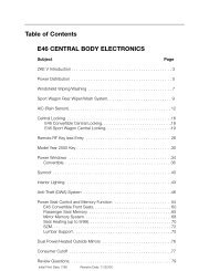
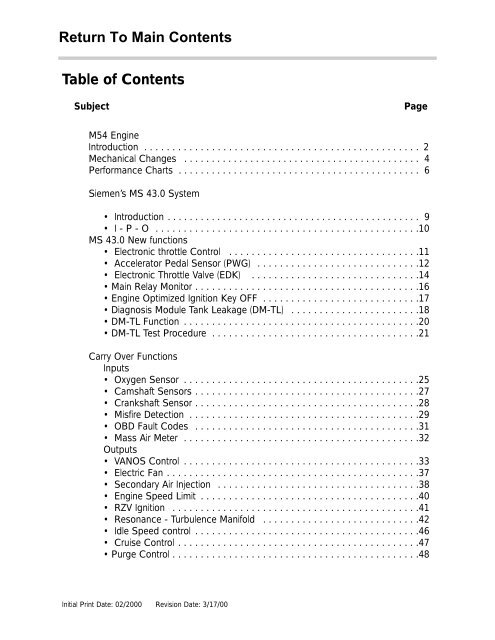
Table of ContentsSubjectPageM54 EngineIntroduction . . . . . . . . . . . . . . . . . . . . . . . . . . . . . . . . . . . . . . . . . . . . . . . . . 2Mechanical Changes . . . . . . . . . . . . . . . . . . . . . . . . . . . . . . . . . . . . . . . . . . . 4Performance Charts . . . . . . . . . . . . . . . . . . . . . . . . . . . . . . . . . . . . . . . . . . . . 6Siemen’s MS 43.0 System• Introduction . . . . . . . . . . . . . . . . . . . . . . . . . . . . . . . . . . . . . . . . . . . . . . 9• I - P - O . . . . . . . . . . . . . . . . . . . . . . . . . . . . . . . . . . . . . . . . . . . . . . .10MS 43.0 New functions• Electronic throttle Control . . . . . . . . . . . . . . . . . . . . . . . . . . . . . . . . . .11• Accelerator Pedal Sensor (PWG) . . . . . . . . . . . . . . . . . . . . . . . . . . . . .12• Electronic Throttle Va<strong>lv</strong>e (EDK) . . . . . . . . . . . . . . . . . . . . . . . . . . . . . .14• Main Relay Monitor . . . . . . . . . . . . . . . . . . . . . . . . . . . . . . . . . . . . . . . .16• Engine Optimized Ignition Key OFF . . . . . . . . . . . . . . . . . . . . . . . . . . . .17• Diagnosis Module Tank Leakage (DM-TL) . . . . . . . . . . . . . . . . . . . . . . .18• DM-TL Function . . . . . . . . . . . . . . . . . . . . . . . . . . . . . . . . . . . . . . . . . .20• DM-TL Test Procedure . . . . . . . . . . . . . . . . . . . . . . . . . . . . . . . . . . . . .21Carry Over FunctionsInputs• Oxygen Sensor . . . . . . . . . . . . . . . . . . . . . . . . . . . . . . . . . . . . . . . . . .25• Camshaft Sensors . . . . . . . . . . . . . . . . . . . . . . . . . . . . . . . . . . . . . . . .27• Crankshaft Sensor . . . . . . . . . . . . . . . . . . . . . . . . . . . . . . . . . . . . . . . .28• Misfire Detection . . . . . . . . . . . . . . . . . . . . . . . . . . . . . . . . . . . . . . . . .29• OBD Fault Codes . . . . . . . . . . . . . . . . . . . . . . . . . . . . . . . . . . . . . . . .31• Mass Air Meter . . . . . . . . . . . . . . . . . . . . . . . . . . . . . . . . . . . . . . . . . .32Outputs• VANOS Control . . . . . . . . . . . . . . . . . . . . . . . . . . . . . . . . . . . . . . . . . .33• Electric Fan . . . . . . . . . . . . . . . . . . . . . . . . . . . . . . . . . . . . . . . . . . . . .37• Secondary Air Injection . . . . . . . . . . . . . . . . . . . . . . . . . . . . . . . . . . . .38• Engine Speed Limit . . . . . . . . . . . . . . . . . . . . . . . . . . . . . . . . . . . . . . .40• RZV Ignition . . . . . . . . . . . . . . . . . . . . . . . . . . . . . . . . . . . . . . . . . . . .41• Resonance - Turbulence Manifold . . . . . . . . . . . . . . . . . . . . . . . . . . . .42• Idle Speed control . . . . . . . . . . . . . . . . . . . . . . . . . . . . . . . . . . . . . . . .46• Cruise Control . . . . . . . . . . . . . . . . . . . . . . . . . . . . . . . . . . . . . . . . . . .47• Purge Control . . . . . . . . . . . . . . . . . . . . . . . . . . . . . . . . . . . . . . . . . . . .48Initial Print Date: 02/2000 Revision Date: 3/17/00
M54 ENGINEART-A0021216M54B30M54B25HORSE POWER 225@5900RPM 184@6000RPMTORQUE 293Nm@3500RPM 240Nm@3500RPMBORE 84mm 84mmSTROKE 89.6mm 75mmCOMPRESSION 10.2:1 10.5:13M54engMS43/ST039/3/17/00
M54 ENGINEMechanical ChangesIn addition to the increased displacement of the M54B30 <strong>engine</strong>, several mechanicalchanges were incorporated into the <strong>engine</strong> for reduced emissions and increased fuel economy.These changes include:• NEW PISTONS - The piston has a shorter skirt compared to the M52 TU and continueswith the graphite coating for friction and emission reducing measures. The piston rings havebeen modified to reduce friction.• CRANKSHAFT - The crankshaft for the 3 liter M54 is adopted from the S52B32 - M3<strong>engine</strong>. The crankshaft for the 2.5 liter is carried over from M52.• CAMSHAFT - The camshaft for the 3 liter M54 is modified with more lift (9.7 mm) andnew va<strong>lv</strong>e springs to accommodate the increased lift. The camshaft of the 2.5 liter M54 iscarried over from the M52 <strong>engine</strong>.• INTAKE MANIFOLD - The intake manifold is modified with shorter ram tubes (20mmshorter on 3 liter/10mm shorter on 2.5 liter). The diameter of the tubes is increased slightly.• INJECTION VALVES - The diameter of the injection pintle has increased slightly for theincreased displacement of the 3 liter <strong>engine</strong>. The injector for the 2.5 liter <strong>engine</strong> carries overfrom M52.ART-INJECTORART-0198U294M54engMS43/ST039/3/17/00
M54 ENGINEMECHANICAL CHANGESNON RETURN FUEL RAIL SYSTEMThe M54 <strong>engine</strong> with MS 43.0 control uses the non return fuel rail system introduced onthe M62 TU <strong>engine</strong>. The system meets running loss compliance without the use of the 3/2-way solenoid va<strong>lv</strong>e currently used on the M52 TU <strong>engine</strong>.ART-FUELRAILThe regulated fuel supply is controlled bythe fuel pressure regulator integrated inthe fuel filter. The fuel return line is alsolocated on the filter.The M54 <strong>engine</strong> uses an Electronic ControlledThrottle Va<strong>lv</strong>e (EDK) for intake air control. Theidle control va<strong>lv</strong>e and turbulence function of theintake manifold carries over from the M52 TU<strong>engine</strong>.5M54engMS43/ST039/3/17/00
M54B30 ENGINE293225ART-HPCHARTB30.6M54engMS43/ST039/3/17/00
M54B25 ENGINE184ARTHPCHARTB25.7M54engMS43/ST039/3/17/00
REVIEW QUESTIONS1. What is the major reason for the development of the M54 <strong>engine</strong>?__________________________________________________________________________2. What are the major mechanical changes that were integrated into the3 liter M54 <strong>engine</strong>?___________________________________________________________________________________________________________________________________________________________________________________________________________________________________________________________________________________________________________________________________________________________________________________8M54engMS43/ST039/3/17/00
SIEMENS ENGINE MANAGEMENT SYSTEMModels: E53 X5, E46, E39, E36 - Z33.0 and 2.5 LiterSOP: 3 liter - 4/00, 2.5 liter 9/00Objectives of the Module:At the end of this section of the handout you will be able to:• Identify the changes that have occurred to the MS 43 system compared to the MS 42• Describe the operation of the new inputs• Describe the operation of the new outputs• Discuss which new components/subsystems relate directly to ULEV compliancyThis new generation Siemens system is designated as MS 43.0.Siemens MS 43.0 is a newly developed <strong>engine</strong> management system to meet the needs ofUltra Low Emission Vehicle (ULEV) compliancy and continuing with present systems is alsoOBD II compliant. This system also includes control of the Motor-driven Throttle Va<strong>lv</strong>e(EDK).The ECM uses a pc-board dual-processor control unit in the SKE housing configuration.The MS 43.0 ECM is flash programmable as seen with previous systems.ECM hardware includes:Modular plug connectors featuring 5 connectors in the SKE housing with 134 pins.• Connector 1 = Supply voltages and grounds• Connector 2 = Peripheral signals (oxygensensors, CAN, etc.)• Connector 3 = Engine signals• Connector 4 = Vehicle signals• Connector 5 = Ignition signalsSpecial features:• Flash EPROM which is adaptable to several M52 LEV <strong>engine</strong>s and has the capability tobe programmed up to 13 times• Once a control unit is installed and coded to a vehicle it cannot be swapped with anothervehicle for diagnosing or replacement (because of EWS 3.3).9M54engMS43/ST039/3/17/00
SYSTEM OVERVIEW I-P-OServiceEngineSoon10M54engMS43/ST039/3/17/00ART-IPO46X.EPS
MS 43 NEW FUNCTIONSELECTRONIC THROTTLE SYSTEM - EMLThe M54 <strong>engine</strong> with MS 43 <strong>engine</strong> control uses an electronic throttle control systemadopted from the ME 7.2 system on the M62 <strong>engine</strong>. The system incorporates an electricthrottle va<strong>lv</strong>e (EDK) and pedal position sensor (PWG) for <strong>engine</strong> power control.The MS 43 control module monitors the PWG input and activates the EDK motor based onthe programmed maps for throttle control. The MS 43 module self checks the activation ofthe EDK via feedback potentiometers motor on the EDK motor.Additional functions of the EML system include:ART-SCANDIAGRAM• Cruise control function• DSC throttle interventions• Maximum <strong>engine</strong> and road speed control11M54engMS43/ST039/3/17/00
MS 43 NEW FUNCTIONSACCELERATOR PEDAL SENSORThe accelerator pedal sensor is similar to the PWG used on the ME 7.2 system. It is integratedinto the accelerator pedal housing. Two hall sensors are used to provide the driver’sinput request for power.The hall sensors receive power (5 volts) and ground from the MS 43 control module andproduce linear voltage signals as the pedal is pressed from LL to VL.PWG SENSOR 1 = 0.5 to 4.5 VPWG SENSOR 2 = 0.5 to 2.0 VHSHSThe MS 43 control module uses thesignal from sensor 1 as the driver’srequest and the signal from sensor 2as plausibility checking.HALL SENSORPOWERSIGNAL 21 2 3 4 5SIGNAL 1MS 43.061460015_________________________________________________________________________________________________________________________________________________________________________________________________________________________________________________________________________________________________________________________________________________________________________________________________12M54engMS43/ST039/3/17/00
MS 43 NEW FUNCTIONSACCELERATOR PEDAL SENSORPWG SIGNAL MONITORING & PWG FAILSAFE OPERATION:• As a redundant safety feature the PWG provides two separate signals from two integralangle hall sensors (HS #1 and HS #2) representing the driver’s request for throttle activation.• If the monitored PWG signals are not plausible, MS 43.0 will only use the lower of thetwo signals as the driver’s pedal request input providing failsafe operation. Throttleresponse will be slower and maximum throttle position will be reduced.• When in PWG failsafe operation, MS 43.0 sets the EDK throttle plate and injection timeto idle (LL) whenever the brake pedal is depressed.• When the system is in PWG failsafe operation, the instrument cluster matrix display willpost “Engine Emergency Program” and PWG specific fault(s) will be stored in memory.E46ICPOT-SIG.__________________________________________________________________________________________________________________________________________________________13M54engMS43/ST039/3/17/00
MS 43 NEW FUNCTIONSEDK THROTTLE POSITION FEEDBACK SIGNALSThe EDK throttle plate is monitored by two integrated potentiometers. The potentiometersprovide linear voltage feedback signals to the control module as the throttle plate is openedand closed.Feedback signal 1 provides a signal from 0.5 V (LL) to 4.5 V (VL).Feedback signal 2 provides a signal from 4.5 V (LL) to 0.5 V (VL)Potentiometer signal 1 is the primary feedback signal of throttle plate position and signal 2is the plausibility cross check through the complete throttle plate movement.ART-EDK.EPS114M54engMS43/ST039/3/17/00ART-E46ICPWG2.
MS 43 NEW FUNCTIONSEDK THROTTLE POSITION FEEDBACK SIGNALSEDK FEEDBACK SIGNAL MONITORING & EDK FAILSAFE OPERATION:• The EDK provides two separate signals from two integral potentiometers (Pot 1 and Pot2) representing the exact position of the throttle plate.• EDK Pot 1 provides the primary throttle plate position feedback. As a redundant safetyfeature, Pot 2 is continuously cross checked with Pot 1 for signal plausibility.• If plausibility errors are detected between Pot 1 and Pot 2, MS 43.0 will calculate theinducted <strong>engine</strong> air mass (from HFM signal) and only utilize the potentiometer signal thatclosely matches the detected intake air mass.- The MS 43.0 uses the air mass signalling as a “virtual potentiometer” (pot 3) for acomparative source to provide failsafe operation.- If MS 43.0 cannot calculate a plausible conclusion from the monitored pots (1 or 2and virtual 3) the EDK motor is switched off and fuel injection cut out is activated(no failsafe operation possible).• The EDK is continuously monitored during all phases of <strong>engine</strong> operation. It is alsobriefly activated when KL 15 is initially switched on as a “pre-flight check” to verify it’smechanical integrity (no binding, appropriate return spring tension, etc). This is accomplishedby monitoring both the motor control amperage and the reaction speed of theEDK feedback potentiometers. If faults are detected the EDK motor is switched off andfuel injection cut off is activated (no failsafe operation possible). The <strong>engine</strong> does howevercontinue to run extremely rough at idle speed.• When a replacement EDK is installed, the MS 43.0 adapts to the new component(required amperage draw for motor control, feedback pot tolerance differences, etc).This occurs immediately after the next cycle of KL 15 for approximately 30 seconds.During this period of adaptation, the maximum opening of the throttle plate is 25%.____________________________________________________________________________________________________________________________________________________________________________________________________________________________________________________________________________________________________________________15M54engMS43/ST039/3/17/00
MS 43 NEW FUNCTIONSMAIN RELAY MONITORThe MS 43.0 system incorporates a new monitoring feature for terminal 87 (KL 87) of themain relay. The relay is monitored internally for the voltage level at KL 87. Five seconds afterthe ignition key is switched on, and the voltage at the KL 15 input is greater than 9 volts,the control module checks the voltage at KL 87.If the voltage difference between the two terminals is greater than 3 volts, a fault will bestored in the ECM.ART-E46ICMS43RELAY_______________________________________________________________________________________________________________________________________________________________________________________________________________________________________16M54engMS43/ST039/3/17/00
MS 43 NEW FUNCTIONSEMISSION OPTIMIZED - IGNITION KEY OFF“Emission Optimized Ignition Key Off” is a programmed feature of the MS 43 control module.After the ECM detects KL 15 being switched OFF, the ignition stays active for two moreindividual coil firings. This means that just two cylinders are fired - not two revolutions.This feature allows residual fuel injected into the cylinders, as the ignition key is switchedoff, to be burned as the <strong>engine</strong> runs down.ART-E46ICEMIOPT________________________________________________________________________________________________________________________________________________________________________________________________________________________________________________________________________17M54engMS43/ST039/3/17/00
MS 43 NEW FUNCTIONSDM-TL (DIAGNOSIS MODULE - TANK LEAKAGE)The M54 <strong>engine</strong> with the Siemens MS43.0 <strong>engine</strong> control system uses the DMTL systemfor fuel system leakage monitoring. The pump is manufactured by Bosch for use with theSiemen’s control system.18M54engMS43/ST039/3/17/00
DM-TL (DIAGNOSIS MODULE - TANK LEAKAGE)FUNCTIONAL OVERVIEW:The DM-TL is located in the drivers side rear wheel well in the X5 and next to the charcoalcanister on the E46 - M54.1. In it’s inactive state, filtered fresh air enters the evaporative system through the sprungopen va<strong>lv</strong>e of the DM-TL.2. When the DME activates the DM-TL for leak testing, it first activates only the pumpmotor. This pumps air through a restrictor orifice (1.0 or 0.5 mm) which causes the electricmotor to draw a specific amperage value. This value is equivalent to the size of therestrictor.3. The solenoid va<strong>lv</strong>e is then energized which seals the evap system and directs the pumpoutput to pressurize the evap system.The evap system is detected as having a large leak if the amperage value is not realized, asmall leak if the same reference amperage is realized or no leak if the amperage value ishigher than the reference amperage.1 2 319T:/Automobiles/ST039/handouts
DM-TL (DIAGNOSIS MODULE - TANK LEAKAGE)FUNCTIONThe DC Motor LDP ensures accurate fuel system leak detection for leaks as small as0.5mm (.020”). The pump contains an integral DC motor which is activated directly by the<strong>engine</strong> control module. The ECM monitors the pump motor operating current as the measurementfor detecting leaks.The pump also contains an ECM controlled change over va<strong>lv</strong>e that is energized closed duringa Leak Diagnosis test. The change over va<strong>lv</strong>e is open during all other periods of operationallowing the fuel system to “breath” through the inlet filter (similar to the full downstroke of the current vacuum operated LDP).20M54engMS43/ST039/3/17/00
LEAK DIAGNOSIS TEST PRECONDITIONSThe ECM only initiates a leak diagnosis test every second time the criteria are met. The criteriais as follows:• Engine OFF with ignition switched OFF.• Engine Control Module still in active state or what is known as “follow up mode” (MainRelay energized, control module and DME components online for extended period afterkey off).• Prior to Engine/Ignition switch OFF condition, vehicle must have been driven for a minimumof 20 minutes.• Prior to minimum 20 minute drive, the vehicle must have been OFF for a minimum of 5hours.• Fuel Tank Capacity must be between 15 and 85% (safe approximation between 1/4 -3/4 of a tank).• Ambient Air Temperature between -7 O C & 35 O C (20 O F & 95 O F )• Altitude < 2500m (8,202 feet).• Battery Voltage between 11.5 and 14.5 VoltsWhen these criteria are satisfied every second time, the ECM will start the Fuel System LeakDiagnosis Test. The test will typically be carried out once a day i.e. once after driving towork in the morning, when driving home in the evening, the criteria are once again met butthe test is not initiated. The following morning, the test will run again.21M54engMS43/ST039/3/17/00
LEAK DIAGNOSIS TESTPHASE 1 - REFERENCE MEASUREMENTThe ECM activates the pump motor. The pump pulls air from the filtered air inlet and passesit through a precise 0.5mm reference orifice in the pump assembly.The ECM simultaneously monitors the pump motor current flow . The motor current raisesquickly and levels off (stabilizes) due to the orifice restriction. The ECM stores the stabilizedamperage value in memory. The stored amperage value is the electrical equivalent of a 0.5mm (0.020”) leak.22M54engMS43/ST039/3/17/00
PHASE 2 - LEAK DETECTIONThe ECM energizes the Change Over Va<strong>lv</strong>e allowing the pressurized air to enter the fuel systemthrough the Charcoal Canister, The ECM monitors the current flow and compares itwith the stored reference measurement over a duration of time.Once the test is concluded, the ECM stops the pump motor and immediately de-energizesthe change over va<strong>lv</strong>e. This allows the stored pressure to vent thorough the charcoal canistertrapping hydrocarbon vapor and venting air to atmosphere through the filter.23M54engMS43/ST039/3/17/00
TEST RESULTSThe time duration varies between 45 & 270 seconds depending on the resulting leak diagnosistest results (developed tank pressure “amperage” / within a specific time period).However the chart below depicts the logic used to determine fuel system leaks.24M54engMS43/ST039/3/17/00
MS 43 CARRY OVER FUNCTIONSINPUT FUNCTIONSBOSCH OXYGEN SENSORSThe MS43.0 system uses Bosch LSH 25 oxygen sensors that function basically the sameas previously used (in Bosch systems). The voltage range is between 0 - 800 mV.PRE 02 SENSORSORPOST 02 SEN-The location remains the same with the pre-cat sensors are mounted on top of the exhaustmanifolds. The catalysts are now integral with the exhaust manifolds (further detailed in theM52 TU <strong>engine</strong> section).POST-CATALYSTSENSORS25M54engMS43/ST039/3/17/00
OXYGEN SENSOR SIGNAL INFLUENCE ON INJECTOR “OPEN” TIMEThe ECM monitors the:• Amplitude of the signal (highest voltage or range sensor is producing)• Switching time of the signal (how fast from lean to rich)• Frequency of complete cycles (how many within a period of time)These characteristics provide info to the ECM that reflect the overall condition of the sensor.POST CATALYTIC CONVERTER SENSOR SIGNALThe post catalyst O2 sensors monitor the efficiency of the catalyst as a requirement of OBDII. This signal also provides feedback of the pre-catalyst sensors efficiency and can causethe ECM to “trim” the ms injection time to correct for slight deviations.• If the catalyst is operating efficiently, most of the remaining oxygen in the exhaust gasis burned (lack of O2 - “constant lean signal”).The sensor signal fluctuates slightly in the higher end of the voltage scale.• If the post sensor shows excessive fluctuations (which echo the scope pattern of the presensor), this indicates that the catalytic converter is not functioning correctly and cannotconsume the O2 (fault set).• If the post sensor fluctuations move out of the normal voltage “window”, this indicatesthat the pre sensor is not performing properly due to slight deterioration. These systemscan also “trim” the ms injection time to compensate for this.The constantly changing oxygen sensor input to the ECM is needed to correct the msinjection time to ensure that the ideal air/fuel ratio is maintained.26M54engMS43/ST039/3/17/00
CAMSHAFT SENSOR-INTAKE AND EXHAUST CAMSHAFTSThe "static" Hall sensors are used so that the camshaft positions are recognized once ignitionis “on” - even before the <strong>engine</strong> is started.The function of the intake cam sensor:• Cylinder bank detection for preliminary injection• Synchronization• Engine speed sensor (if crankshaft speed sensor fails)• Position control of the intake cam (VANOS)The exhaust cam sensor is used for position control of the exhaust cam (VANOS)If these sensors fail there are no substitute values, the system will operate in the failsafemode with no VANOS adjustment. The <strong>engine</strong> will still operate, but torque reduction will benoticeable.NOTE: Use caution on repairs as not to bend the impulse wheelsEXHAUSTTWO POSITION PISTONHOUSING WITHINTERNAL/EXTERNALHELICAL GEAR CUPMS MS42 43.0ECMSENSORINTAKEKL 15SOLENOIDVENTSENSORVENTKL 15MS42.0 43.0ECMTWO POSITION PISTON HOUSINGWITH INTERNAL/EXTERNALHELICAL GEAR CUPENGINEOIL SUPPLYSOLENOIDOIL TEMP.SENSORMS MS42.0 43.027M54engMS43/ST039/3/17/00
CRANKSHAFT SENSORThe crankshaft sensor is a dynamic Hall-effect sensor (mounted through the <strong>engine</strong> block),the signal is sent the moment the crankshaft begins to rotate.The pulse wheel is mounted directly to the crankshaft as seen on previous models.MS 43.0SMOOTH RUNNING ENGINENOTE SQUARE WAVEENGINE MISFIRE DETECTED____________________________________________________________________________________________________________________________________________________________________________________________________________28M54engMS43/ST039/3/17/00
MISFIRE DETECTIONAs part of the CARB/OBD regulations the <strong>engine</strong> control module must determine if misfireis occurring and also identify the specific cylinder(s) and the severity of the misfire event,and whether it is emissions relevant or catalyst damaging. In order to accomplish thesetasks the control module monitors the crankshaft for acceleration losses during firing segmentsof each cylinder based on firing order.Misfire Detection Example: M54 (6 Cyl.) with Siemens SystemThe misfire/<strong>engine</strong> roughness calculation is derived from the differences in the period duration(T) of individual increment gear segments. Each segment period consist of an angularrange of 120° crank angle that starts 78° before Top Dead Center (TDC).If the expected period duration is greater than the permissible value a misfire fault for theparticular cylinder is stored in the fault memory of the ECM. Depending on the level of misfirerate measured the control unit will illuminate the "Service Engine Soon" light, may cutofffuel to the particular cylinder and may switch lambda operation to open-loop. All misfirefaults are weighted to determine if the misfire is emissions relevant or catalyst damaging._________________________________________________________________________________________________________________________________________________________________________________________________________________________________________________________________________________________________________________________________________________________________________________________________________________________________________________________________________________________________________________________________________________________________________________________________________29M54engMS43/ST039/3/17/00
EMISSIONS RELEVANT:During an interval of 1000 crankshaft revolutions the misfire events of all cylinders areadded and if the sum is greater than a predetermined value a fault will be set identifying theparticular cylinder(s). The “Service Engine Soon” light will be illuminated during and afterthe second cycle if the fault is again present.CATALYST DAMAGING:During an interval of 200 crankshaft revolutions the misfire events of all cylinders are addedand if the sum is greater than a predetermined value a fault will be set identifying the particularcylinders(s). The “Service Engine Soon” lamp:• On vehicles with a Siemens Control Module (M54 <strong>engine</strong>s) - the lamp will immediately goto a steady illumination since fuel to the injector(s) is removed. Fuel cut-off to the cylinderwill resume after several (>> 7) periods of decel if crankshaft sensor adaptation is successfullycompleted or the <strong>engine</strong> is shut-off and restarted.In each case the number of misfire events permitted is dependent on <strong>engine</strong> speed, loadand temperature map.The process of misfire detection continues well after the diagnostic drive cycle requirementshave been completed. Misfire detection is an on-going monitoring process that is only discontinuedunder certain conditions.Misfire detection is only disabled under the following conditions:REQUIREMENTSEngine SpeedEngine LoadThrottle AngleTimingEngine Start-upA/CDecel fuel cut-offRough road recognitionASC ControlSTATUS/CONDITION< 512 RPMVarying/UnstableVarying/UnstableTiming retard request active (i.e. knockcontrol - ASC, AGS)Up to 5 seconds after start-upUp to 0.5 seconds after A/C activationActiveActiveActive_________________________________________________________________________________________________________________________________________________________________________________________________________30M54engMS43/ST039/3/17/00
OBD II - Misfire FaultsFAILEDCOMPONENTPOSSIBLE FAULT MISFIREEFFECT/LOCATIONFAILEDCOMPONENTPOSSIBLE FAULT MISFIREEFFECT/LOCATIONSpark plug electrode gap too small affected cylinderselectrodes missing affected cylinderselectrodes oil/fuel soaked affected cylinderselectrodes oil/feul soakedfouledspark plug ceramic broken affected cylindersoil level too high most likely more thanone cylinder affectedoil foamingoil level too high, oil/fuel fouledheat range too coldcrank case ventilation defective most likely more thanone cylinder affectedSpark plug connector wet, water or moisture most likely more thanone cylinder affectedbroken affected cylindersIgnition Coil internal defect, arcing affected cylindersConnectors ignition corrosion one or more cylinderspin backed out one or more cylindersplug loose one or more cylindersloose wire from connector one or more cylindersInjection Va<strong>lv</strong>e metal filing on the affectedcylindersleaking on the affectedcylinderscarbon fouled one or more cylindersdirty/contaminated one or more cylindersInjector connectors corrosion one or more cylinderspin backed out one or more cylindersplug loose one or more cylindersloose wire from connector one or more cylindersIntake manifold leaks intake plenum, unmetere airleak (i.e. injector seals)Intake/Exhaust va<strong>lv</strong>e carbon built up (intake) most likely more thanone cylinder affectedburnt or damaged on the affectedcylindersoverrev:intake or exhaust va<strong>lv</strong>es leaking (bent)most likely more thanone cylinder affectedCamshaft broken most likely more than onecylinder affectedPiston hole in piston crown/pistonseized in boreHydraulic lash adjusters(HVA)defective: i.e. oil borerestricted/blockedon the affected cylinderson the affected cylinders<strong>engine</strong> oil pressure built uptoo slowFuel pressure fuel pump, pressure too low most likely cyl. 1-3 (frontcylinders)fuel filter restricted/ blocked most likely cyl. 1-3 (frontcylinders)fuel pump, pressure build up too slow after startmost likely cyl. 1-3 (frontcylinders)leaking fuel feed lines most likely cyl. 1-3 (frontcylinders)pressure regulator defective most likely cyl. 1-3 (front(metal filing)cylinders)running loss va<strong>lv</strong>e defective most likely cyl. 1-3 (frontcylinders)fuel tank empty most likely cyl. 1-3 (frontcylinders)siphon jet pump and fuel most likely cyl. 1-3 (fronttank emptycylinders)water in fuel tank most likely more than onecylinder affectedFuel high content oxygenated one or more cylindersnon anti carbon additives one or more cylindersOxygen sensor excessive mixture deviation only the affected bankPurge sytem excessive rich mixture dueto high ambient temperatureCrank sensor/incrementwheelone or more banksblocked fuel tank vent inlet all cylindersincorrect input signal for all cylindersmisfire detectionincrement wheel loose all cylindersincrement wheel damaged affected segmentgap between sensor and affected segmentincrement wheelfly wheel damagedCatalyst damaged exhaust back pressure on only the afftected bankthe affected bankDME final stage igntion/injectors all cylinder31M54engMS43/ST039/3/17/00
MASS AIR FLOW SENSOR HFMThe Siemens mass air flow sensor is functionally the same as in the past. The designation2 Type B simply indicates that it is smaller in design. The mass air meter has a diameter of85 mm.________________________________________________________________________________________________________________________________________________________________________________________________32M54engMS43/ST039/3/17/00
MS 43 CARRY OVER FUNCTIONSOUTPUT FUNCTIONS -VANOS CONTROLWith the double VANOS system, the va<strong>lv</strong>e timing is changed on both the intake and theexhaust camshafts.Double VANOS provides the following benefits:• Torque increase in the low to mid (1500 - 2000 RPM) range without power loss in theupper RPM range.• Less incomplete combustion when idling due to less camshaft overlap (also improvesidle speed characteristics).• Internal exhaust gas recirculation (EGR) in the part load range (reduces NOx and postcombustionof residual gasses in the exhaust)• Rapid catalyst warm up and lower “raw” emissions after cold start.• Reduction in fuel consumptionDouble VANOS consists of the following parts:• Intake and exhaust camshafts with helical gear insert• Sprockets with adjustable gears• VANOS actuators for each camshaft• 2 three-way solenoid switching va<strong>lv</strong>es• 2 impulse wheels for detecting camshaft position• 2 camshaft position sensors (Hall effect)The “initial” timing is set by gear positioning (refer to the Repair Instructions for details) andthe chain tensioner. As with the previous VANOS, the hydraulically controlled actuatorsmove the helical geared cups to regulate camshaft timing. The angled teeth of the helicalgears cause the pushing movement of the helical cup to be converted into a rotationalmovement. This rotational movement is added to the turning of the camshafts and causethe camshafts to “advance” or “retard”. The adjustment rate is dependent oil temperature,oil pressure, and <strong>engine</strong> RPM.33M54engMS43/ST039/3/17/00
NOTE: With extremely hot oil temperatures Vanos is deactivated (Power loss). If the oil istoo thick (wrong viscosity) a fault could be set.When the <strong>engine</strong> is started, the camshafts are in the “failsafe” position (deactivated). Theintake camshaft is in the RETARDED position - held by oil pressure from the sprung opensolenoid. The exhaust camshaft is in the ADVANCED position - held by a preload spring inthe actuator and oil pressure from the sprung open solenoid.After 50 RPM (2-5 seconds) from <strong>engine</strong> start, the ECM is monitoring the exact camshaftposition.The ECM positions the camshafts based on <strong>engine</strong> RPM and the throttle position signal.From that point the camshaft timing will be varied based on intake air and coolant temperatures.The double VANOS system is “fully variable”. When the ECM detects the camshafts are inthe optimum positions, the solenoids are modulated (approximately 100-220 Hz) maintainingoil pressure on both sides of the actuators to hold the camshaft timing.CAUTION: The VANOS MUST be removed and installed exactly as described in the RepairInstructions!NOTE: If the VANOS camshaft system goes to the failsafe mode (deactivated) there will bea noticeable loss of power. This will be like driving with retarded ignition or starting from astop in third gear.TWO POSITION PISTONHOUSING WITHINTERNAL/EXTERNALHELICAL GEAR CUPMS 43.0MS42ECMSENSOREXHAUSTINTAKEKL 15SOLENOIDVENTSENSORVENTKL 15MS MS42.0 43.0ECMTWO POSITION PISTON HOUSINGWITH INTERNAL/EXTERNALHELICAL GEAR CUPENGINEOIL SUPPLYSOLENOIDOIL TEMP.SENSOR34M54engMS43/ST039/3/17/00MS MS42.0 43.0
DEACTIVATEDTWO POSITION PISTONHOUSING WITHINTERNAL/EXTERNALHELICAL GEAR CUPKL 15MS 43.0MS42ECMSENSOREXHAUSTINTAKEEXHAUST: Advancedpiston moved inSOLENOIDVENTVENTSENSORKL 15INTAKE: Retard pistonmoved outMS 43.0MS42.0ECMTWO POSITION PISTON HOUSINGWITH INTERNAL/EXTERNALHELICAL GEAR CUPENGINEOIL SUPPLYSOLENOIDOIL TEMP.SENSORMS MS42.0 43.0ACTIVATEDTWO POSITION PISTONHOUSING WITHINTERNAL/EXTERNALHELICAL GEAR CUPKL 15SOLENOIDMS 43.0MS42ECMSENSOREXHAUSTINTAKEEXHAUST: Advancedpiston moved outSENSORVENTVENTKL 15INTAKE: Retard pistonmoved inMS 43.0MS42.0ECMTWO POSITION PISTON HOUSINGWITH INTERNAL/EXTERNALHELICAL GEAR CUPENGINEOIL SUPPLYSOLENOIDMS 43.0MS42.0OIL TEMP.SENSOR35M54engMS43/ST039/3/17/00
The dual VANOS in conjunction with the variable intake manifold provides an additionalemission control feature.Because of the improved combustion, the camshaft timing is adjusted for more overlap.The increased overlap supports internal exhaust gas recirculation (EGR) which reducestailpipe emissions and lowers fuel consumption.During the part load <strong>engine</strong> range, the intake camshaft overlap opens the intake va<strong>lv</strong>e. Thisallows limited exhaust gas reflow the intake manifold.The “internal” EGR reduces the cylinder temperature thus lowering NOx. This feature providesEGR without the external hardware as seen on previous systems.OUTLET-VANOS(228/80-105)INLET-VANOS(228/80-120)SECONDARYAIRINJECTION(AIR FILTER)INT. EGRMDKINLETTURBULENCEIDLE AIRCONTROL VALVECATALYSTCLOSE TOENGINE36M54engMS43/ST039/3/17/00
ELECTRIC FANThe electric cooling fan is now controlled by the ECM. The ECM uses a remote power outputfinal stage (mounted on the fan housing)The power output stage receives power from a 50 amp fuse (located in glove box abovethe fuse bracket). The electric fan is controlled by a pulse width modulated signal from theECM.The fan is activated based on the ECM calculation(sensing ratio) of:• Coolant outlet temperature• Calculated (by the ECM) catalyst temperature• Vehicle speed• Battery voltage• Air Conditioning pressure (calculated by IHKAand sent via the K-Bus to the ECM)MS 43.0MS42.0POWEROUTPUT STAGENOTE: If the ECM indicates a fault check the fan for freedom of movementAfter the initial test has been performed, the fan is brought up to the specified operatingspeed. At 10% (sensing ratio) the fan runs at 1/3 speed. At a sensing ratio of between 90-95% the fan is running at maximum speed. Below 10% or above 95% the fan is stationary.The sensing ratio is suppressed by a hysteresis function, this prevents speed fluctuation.When the A/C is switched on, the electric fan is not immediately activated.After the <strong>engine</strong> is switched off, the fan may continue to operate at varying speeds (basedon the ECM calculated catalyst temperature). This will cool the radiator down from a heatsurge (up to 10 minutes).37M54engMS43/ST039/3/17/00
SECONDARY AIR INJECTIONThis ECM controlled function remains unchanged fromthe previous Siemens MS system, however there is ahardware change.The Air Injection Inlet Va<strong>lv</strong>e mounts directly to the cylinderhead, with a passageway machined through thehead. This eliminates the external Air Injection manifolddistribution pipes to the exhaust manifolds.SECONDARY AIR INJECTION MONITORINGIn order to reduce HC and CO emissions while the <strong>engine</strong> is warming up, BMW implementedthe use of a Secondary Air Injection System in. Immediately following a cold <strong>engine</strong>start (-10 - 40°C) fresh air/oxygen is injected directly into the exhaust manifold. By injectingoxygen into the exhaust manifold:• The warm up time of the catalyst is reduced• Oxidation of the hydrocarbons is acceleratedThe activation period of the air pump can vary depending on <strong>engine</strong> type and operatingconditions.Conditions for Secondary Air Pump Activation:REQUIREMENTSSTATUS/CONDITIONM52 MS 43.0 & M44STATUS/CONDITIONM73Oxygen sensor Open Loop Open LoopOxygen sensor heating Active ActiveEngine coolant temperature -10 to 40ºC* -10 to 40ºC* StageEngine bad Predefined Range Predefined RangeEngine speed Predefined Range Predefined RangeFault CodesNo Secondary Air Faults“currently present”No Secondary Air Faults“currently present”*NOTE: Below -10°C the air injection pump is activated only as a preventive measure toblow out any accumulated water vapor that could freeze in the system.38M54engMS43/ST039/3/17/00
The Secondary Air Injection System is monitored via the use of the pre-catalyst oxygen sensor(s).Once the air pump is active and is air injected into the system the signal at the oxygensensor will reflect a lean condition. If the oxygen sensor signal does not change withina predefined time a fault will be set and identify the faulty bank(s). If after completing thenext cold start and a fault is again present the "Service Engine Soon" light will be illuminated.Example: Secondary Air Injection Monitoring (M54-Siemens System)During a cold start condition air is immediately injected into the exhaust manifold and sincethe oxygen sensors are in open loop at this time the voltage at the pre catalyst sensor willreflect a lean condition) and will remain at this level while the air pump is in operation. Oncethe pump is deactivated the voltage will change to a rich condition until the system goesinto closed loop operation.M54 System Operation:The pump draws air through its own air filter and delivers it to both exhaust manifoldsthrough a non-return (shutoff va<strong>lv</strong>e). The non-return va<strong>lv</strong>e is used to:1. Control air injection into the exhaust manifold - A vacuum controlled va<strong>lv</strong>e will open thepassageway for air to be injected once a vacuum is applied.2. Prevent possible backfires from traveling up the pipes and damaging the air pump whenno vacuum is applied.The control module activates the vacuum vent va<strong>lv</strong>e whenever the air pump is energized.Once the vacuum vent va<strong>lv</strong>e is energized a vacuum is applied to the non-return va<strong>lv</strong>e whichallows air to be injected into the exhaust manifold. A vacuum is retained in the lines, by theuse of a check va<strong>lv</strong>e, in order to allow the non-return va<strong>lv</strong>e to be immediately activated oncold <strong>engine</strong> start up. When the vacuum/vent va<strong>lv</strong>e is not energized, the vacuum to thenon-return va<strong>lv</strong>e is removed and is vented to atmosphere.39T:/Automobiles/ST039/handouts
ENGINE/VEHICLE SPEEDLIMITATIONFor <strong>engine</strong>/vehicle speed limitation, the ECM will deactivate injection for individual cylinders,allowing a smoother limitation transition. This prevents over-rev when the <strong>engine</strong> reachesmaximum RPM (under acceleration), and limits top vehicle speed (approx. 128 mph).DSCMS 43.0________________________________________________________________________________________________________________________________________________________________________________________________________________________________________________________________________________________________________________________________40M54engMS43/ST039/3/17/00
RZV IGNITION SYSTEMThe Siemens MS43.0 system uses a multiple spark ignition function. The purpose of multipleignition is:• Provide clean burning during <strong>engine</strong> start up and while idling (reducing emissions).• This function helps to keep the spark plugs clean for longer service life (new BMWlonglife plugs).MS 43.0Multiple ignition is active up to an <strong>engine</strong> speed of approximately 1350 RPM (varied with<strong>engine</strong> temperature) and up to 20 degrees after TDC.Multiple ignition is dependent on battery voltage. When the voltage is low, the primary currentis also lower and a longer period of time is required to build up the magnetic field in thecoil(s).• Low battery voltage = less multiple ignitions• High battery voltage = more multiple ignitionsThe 240 ohm shunt resistor is still used on the MS43.0 system for detecting secondary ignitionfaults and diagnostic purposes.41M54engMS43/ST039/3/17/00
RESONANCE/TURBULENCE INTAKE SYSTEMOn the M54, the intake manifold is split into 2 groups of 3 (runners) which increases lowend torque. The intake manifold also has separate (internal) turbulence bores which channelsair from the idle speed actuator directly to one intake va<strong>lv</strong>e of each cylinder (matchingbore of 5.5mm in the cylinder head).Routing the intake air to only one intake va<strong>lv</strong>e causes the intake to swirl in the cylinder.Together with the high flow rate of the intake air due to the small intake cross sections, thisresults in a reduction in fluctuations and more stable combustion.MAIN MAINIFOLDRAM TUBERESONANCE TUBEMS42.0MS 43.0MAGNETICVALVEVACUUMUNITMDKEDKHFMIDLE AIR CONTROL VALVE(ZWD)RESONANCE MANIFOLDTURBULENCE MANIFOLDTURBULENCE BORE 0:5.5mmCRANKCASE VENTILATION____________________________________________________________________________________________________________________________________________________________________________________________________________________________________________________________________42M54engMS43/ST039/3/17/00
RESONANCE SYSTEMThe resonance system provides increased <strong>engine</strong> torque at low RPM, as well as additionalpower at high RPM. Both of these features are obtained by using a resonance flap (inthe intake manifold) controlled by the ECM.During the low to mid range rpm, the resonance flap is closed. This produces a long/singleintake tube for velocity, which increases <strong>engine</strong> torque.During mid range to high rpm, the resonance flap is open. This allows the intake air to pullthrough both resonance tubes, providing the air volume necessary for additional power atthe upper RPM range.When the flap is closed , this creates another “dynamic” effect. For example, as the intakeair is flowing into cylinder #1, the intake va<strong>lv</strong>es will close. This creates a “roadblock” for thein rushing air. The air flow will stop and expand back (resonance wave back pulse) with thein rushing air to cylinder #5. The resonance “wave”, along with the intake velocity,enhances cylinder filling.The ECM controls a solenoid va<strong>lv</strong>e for resonance flap activation. At speeds below 3750RPM, the solenoid va<strong>lv</strong>e is energized and vacuum supplied from an accumulator closesthe resonance flap. This channels the intake air through one resonance tube, but increasesthe intake velocity.When the <strong>engine</strong> speed is greater than 4100 RPM (which varies slightly - temperature influenced),the solenoid is de-energized. The resonance flap is sprung open, allowing flowthrough both resonance tubes, increasing volume.43M54engMS43/ST039/3/17/00
#1 Cylinder Intake Va<strong>lv</strong>e openLow to Mid Range RPM( Intake Air Bounce EffectLow to Mid Range RPM(
#1 Cylinder Intake Va<strong>lv</strong>e open -Intake air drawn from bothresonance tubes.Mid to High Range RPM(>3750 RPM)EDKMS 43.0#5 Cylinder Intake Va<strong>lv</strong>e open -Intake air drawn from bothresonance tubes.Mid to High Range RPM(>3750 RPM)EDKMS 43.045M54engMS43/ST039/3/17/00
IDLE SPEED CONTROLThe ECM determines idle speed by controlling an idle speed actuator (dual winding rotaryactuator) ZWD 5.The basic functions of the idle speed control are:• Control the initial air quantity(at air temperatures
CRUISE CONTROLCruise control is integrated into the ECM because of the EDK operation.Cruise control functions are activated directly by the multifunction steering wheel to theECM. The individual buttons are digitally encoded in the MFL switch and is input to the ECMover a serial data wire.EDKMS 43.0DSCThe ECM controls vehicle speed by activation of the Electronic Throttle Va<strong>lv</strong>e (EDK)The clutch switch disengages cruise control to prevent over-rev during gear changes.The brake light switch and the brake light test switch are input to the ECM to disengagecruise control as well as fault recognition during <strong>engine</strong> operation of the EDK.Road speed is input to the ECM for cruise control as well as DSC regulation. The vehiclespeed signal for normal <strong>engine</strong> operation is supplied from the DSC module (right rear wheelspeed sensor). The road speed signal for cruise control is supplied from the DSC module.This is an average taken from both front wheel speed sensors, supplied via the CAN bus.47M54engMS43/ST039/3/17/00
PURGE VALVEThe purge va<strong>lv</strong>e (TEV) is activated at 10 Hz by the ECM to cycle open, and is sprungclosed. The va<strong>lv</strong>e is identical to the purge va<strong>lv</strong>e used on the Siemens MS 42 system.________________________________________________________________________________________________________________________________________________________________________________________________________________________________________________________________________________________________________________________________________________________________________________________________________________________________________________________________48M54engMS43/ST039/3/17/00
REVIEW QUESTIONS1. List the major changes to the Siemens MS 43.3 system from MS 42:_________________________________________________________________________________________________________________________________________________________________________________________________________________________________________________________________________________________________________________________________________________________________________________________________2. What type of signal does the Hall Sensor - PWG provide to ECM for throttle request?_____________________________________________________________________________3. What PWG signal is used if PWG has a plausibility error?_____________________________________________________________________________4. What is the purpose of the KL 87 main relay monitor in the ECM?_____________________________________________________________________________5. Why is the ignition left ON after KL 15 is switched OFF?_____________________________________________________________________________6. Describe the operation of the DM-TL system on MS 43.0._________________________________________________________________________________________________________________________________________________________________________________________________________________________________________________________________________________________________________________________________________________________________________________________________7. Describe the operation of the turbulence - resonance manifold.___________________________________________________________________________________________________________________________________________________________________________________________________________________________________________________________________________________________________________________________________________________________________________________________________________________________________________________________________________________________________________________________________________________________49M54engMS43/ST039/3/17/00