Humidifier Brochure
Humidifier Brochure
Humidifier Brochure

Create successful ePaper yourself
Turn your PDF publications into a flip-book with our unique Google optimized e-Paper software.
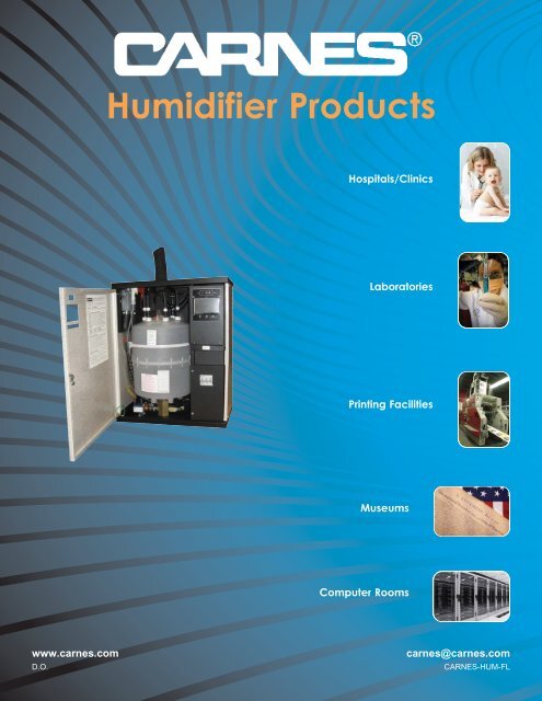
<strong>Humidifier</strong> Products<br />
Hospitals/Clinics<br />
Laboratories<br />
Printing Facilities<br />
Museums<br />
Computer Rooms<br />
www.carnes.com<br />
D.O.<br />
carnes@carnes.com<br />
CARNES-HUM-FL
Steam <strong>Humidifier</strong>s<br />
CARNES MICROPROCESSOR CONTROLLED STEAM HUMIDIFIERS use ordinary untreated<br />
tap water and convert it to mineral free steam for humidity control in commercial,<br />
industrial, institutional and residential applications.<br />
ECONOMICAL<br />
Disposable Cylinders Eliminate Periodic Maintenance For Reduced Maintenance Costs<br />
Fast and Easy Installation<br />
Reliable Electronic Components For Long Life<br />
EFFICIENT<br />
Circuit Board Utilizes Microprocessor To Maximize Energy Conservation<br />
Exclusive Circuit Board Design With Attached True Touchscreen Control Display<br />
VERSATILE<br />
Digital Output On A True Touchscreen Control Display Providing Status and Help Buttons For Operational Details and<br />
Troubleshooting<br />
Capacities Up To 200 Pounds Of Steam Per Hour Per Single Unit<br />
Utilize any On-Off Humidistat, Carnes Proportional Humidistat or External Signal From DDC Controls<br />
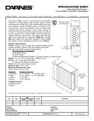
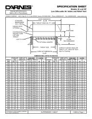
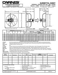
Flexible steam<br />
hose connects to<br />
distribution pipe.<br />
Easy access<br />
“on-off-drain”<br />
switch.<br />
Hinged and removable<br />
door provides easy<br />
access for service.<br />
True<br />
Touchscreen<br />
control display.<br />
20 gauge metal partition<br />
covers line voltage wiring<br />
for added safety.<br />
Door lock<br />
prevents<br />
unauthorized<br />
adjustments.<br />
Optional internal circuit<br />
breaker available. Please<br />
note: certain units require<br />
circuit breakers per NEC<br />
48 amp guidelines.<br />
HBGH Shown<br />
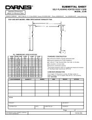
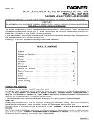
Disposable plastic cylinder eliminates<br />
periodic maintenance.<br />
The simplicity and unique advantages of humidity from<br />
directly boiling water in disposable cylinders has been well<br />
known since Carnes pioneered the concept in North America<br />
in 1969. Pan type humidifiers require messy, time consuming<br />
cleaning that may require the use of acids. Electric heating<br />
elements in pan type units may also require replacement.<br />
Easily changeable steam cylinders containing electrodes<br />
can be replaced in less than five minutes.<br />
Cut-away used<br />
steam cylinder<br />
showing mineral deposits.
Applications<br />
COMFORT<br />
Temperature and relative humidity affect the comfort and<br />
well being of all living things. High temperatures require low<br />
humidity to maintain comfort conditions, while low<br />
temperatures can more easily be tolerated at high relative<br />
humidity. Humidification occurs when air is moisturized by a<br />
humidification unit or when hygroscopic materials (materials<br />
containing moisture) lose moisture to drier air. Proper<br />
humidification is widely accepted as healthy, minimizing<br />
employee illness and lost work time.<br />
MATERIALS STORAGE<br />
Paper, fabrics, wood, plastic, chemicals and most other<br />
materials are hygroscopic. Their water content depends on<br />
the humidity of the air around them. If air is too dry, these<br />
substances lose moisture until an equilibrium is reached<br />
between hygroscopic materials and the air.<br />
PROCESS<br />
Process operations, such as data processing areas, are<br />
affected by two major humidity factors: hygroscopic material<br />
and generation of static electricity.<br />
Hygroscopic material used in the process influences material<br />
weights, dimensions and workability.<br />
Static electricity can totally disrupt high speed process<br />
operations as found in a data processing center, paper or film<br />
handling business. Created by friction between two<br />
substances, static electricity can be prevented by proper<br />
humidification of the process environment.<br />
RECOMMENDED TEMPERATURE AND HUMIDITY RANGE<br />
APPLICATION TEMP F o R.H. %<br />
Computer Rooms 72+2 50+5<br />
Office Buildings 70-74 20-30<br />
Libraries & Museums 68-72 40-55<br />
Archival Libraries & Museums 55-65 35<br />
Art Storage 60-72 50+2<br />
Stuffed Animals 40-50 50<br />
Bowling Centers 70-74 20-30<br />
Health Facilities<br />
Full Term Nursery 75 30min.-60max.<br />
Special Care Nursery 75-80 30min.-60max.<br />
Patient Rooms 75 30<br />
Intensive Care 75-80 30min.-60max.<br />
Operating Rooms 68-76 50min.-60max.<br />
Recovery Rooms 75 50min.-60max.<br />
Electrical Instrument Mfg. 70 50-55<br />
Fur Storage 40-50 55-65<br />
Photo Film Darkroom 70-72 45-55<br />
Photo Print Darkroom 70-72 45-55<br />
Photo Drying Room 90-100 35-45<br />
Photo Finishing Room 72-75 40-55<br />
Cellophane Wrapping 75-80 45-65<br />
Animal Laboratories<br />
Mouse, Rat 64-79 40-70<br />
Cat 65-85 30-70<br />
Dog 65-85 30-70<br />
Primate 65-84 30-70<br />
Clean Rooms 67-77 40-55<br />
Printing Plants<br />
Lithography 76-80 43-47+2<br />
Rotogravure 45-50+2<br />
Collotype 80+2 85+2<br />
Platemaking 75-80+2 45+2<br />
Telephone Terminal Rooms 72-78 30-40<br />
Radio and TV Studios 74-78 30-40<br />
+ = plus or minus<br />
Reprinted with permission of the American Society of Heating, Refrigerating<br />
and Air Conditioning Engineers, Inc., Atlanta, GA 30329.<br />
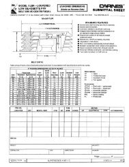
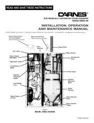
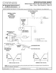
Operation<br />
Upon a signal from external controls the circuit board opens<br />
a fill solenoid valve, allowing water to flow across an air gap<br />
into a standpipe. The standpipe provides a column of water<br />
to be fed into the cylinder using gravity. The air gap prevents<br />
back flow into the water supply and prevents the cylinder<br />
from becoming a pressure vessel. The steam cylinder<br />
operates at a pressure of approximately 1/2 psi.<br />
The circuit board also closes a power contactor allowing<br />
current to flow to vertical electrodes sealed inside the<br />
cylinder. Current flows between the electrodes using<br />
minerals in the water as a conductor. The water is heated to<br />
boiling and converted to steam which leaves the cylinder<br />
through the flexible steam hose which is connected to the<br />
steam distributor pipe.<br />
The circuit board reacts to current flow between the electrodes<br />
and automatically opens the fill solenoid valve when<br />
more water is required to maintain the desired output rate,<br />
and closes when the desired rate is reached. The operation of<br />
the drain solenoid valve is automatically controlled by the<br />
circuit board which responds to any changes in water<br />
conditions and drains the required quantity of water to<br />
provide stable operation and long cylinder life.<br />
As mineral deposits build up within the cylinder the water<br />
level will slowly rise to uncovered electrode surfaces to maintain<br />
the desired steam output rate. When mineral deposits<br />
have covered all available electrode surface areas, current<br />
flow will be reduced to a level where the desired steam<br />
output cannot be reached and the service light will signal<br />
the need for maintenance. When the cylinder is filled with<br />
minerals it is easily changed in less than five minutes.<br />
FILL<br />
SOLENOID VALVE<br />
NON CONTACT<br />
HIGH WATER<br />
SENSOR<br />
OVERFLOW<br />
TUBE<br />
AIR GAP<br />
STEAM<br />
WATER<br />
STAND<br />
PIPE<br />
STEAM<br />
DISTRIBUTOR<br />
PIPE<br />
STEAM<br />
HOSE<br />
FROM POWER<br />
CONTACTOR<br />
TO DRAIN<br />
CYLINDER<br />
VERTICAL<br />
ELECTRODES<br />
DRAIN<br />
SOLENOID<br />
VALVE
UNIT AVAILABILITY MODELS AVAILABLE AND ELECTRICAL DATA<br />
HBAH<br />
HCAH<br />
HSAH<br />
HTAH<br />
HBDH<br />
HCDH<br />
HSDH<br />
HTDH<br />
HBGH<br />
HCGH<br />
HSGH<br />
HTGH<br />
Optional<br />
Cir.<br />
Breaker*<br />
Model<br />
Max<br />
Lb/Hr Volt Ph kW<br />
Line<br />
Amp<br />
Disc.<br />
Size<br />
Steam<br />
Cylinder<br />
H_AHAU 5 120 1 1.725 14.4 25 1-20 Amp AX220<br />
H_AHBU 5 208 1 1.725 8.3 15 1-15 Amp AX380<br />
H_AHDU 5 230 1 1.725 7.5 15 1-20 Amp AX380<br />
H_AHFU 5 277 1 1.725 6.2 15 1-15 Amp AX380<br />
H_AHLU 5 380 1 1.725 4.5 15 1-15 Amp AX600<br />
H_AHQU 5 415 1 1.725 4.2 15 1-15 Amp AX600<br />
H_AHMU 5 460 1 1.725 3.7 15 1-15 Amp AX700<br />
H_AHNU 5 575 1 1.725 3.0 15 1-15 Amp AX700<br />
H_AHAU 10 120 1 3.45 28.7 45 1-40 Amp AX220<br />
H_AHBU 10 208 1 3.45 16.6 25 1-25 Amp AX380<br />
H_AHDU 10 230 1 3.45 15.0 25 1-25 Amp AX380<br />
H_AHFU 10 277 1 3.45 12.4 20 1-20 Amp AX380<br />
H_AHLU 10 380 1 3.45 9.1 15 1-15 Amp AX600<br />
H_AHQU 10 415 1 3.45 8.3 15 1-15 Amp AX600<br />
H_AHMU 10 460 1 3.45 7.5 15 1-15 Amp AX700<br />
H_AHNU 10 575 1 3.45 6.0 15 1-15 Amp AX700<br />
H_DHBU 20 208 1 6.9 33.1 50 1-45 Amp B500<br />
H_DHDU 20 230 1 6.9 29.9 45 1-40 Amp B500<br />
H_DHFU 20 277 1 6.9 24.9 40 1-35 Amp B500<br />
H_DHLU 20 380 1 6.9 18.1 30 1-30 Amp B600<br />
H_DHQU 20 415 1 6.9 16.6 25 1-25 Amp B600<br />
H_DHMU 20 460 1 6.9 15.0 25 1-25 Amp B700<br />
H_DHNU 20 575 1 6.9 12.0 20 1-15 Amp B700<br />
H_DHCU 20 208 3 6.9 19.1 30 1-25 Amp B500<br />
H_DHEU 20 230 3 6.9 17.3 30 1-25 Amp B500<br />
H_DHTU 20 380 3 6.9 10.4 20 1-20 Amp B600<br />
H_DHWU 20 415 3 6.9 9.6 20 1-20 Amp B600<br />
H_DHGU 20 460 3 6.9 8.6 15 1-15 Amp B700<br />
H_DHHU 20 575 3 6.9 6.9 15 1-15 Amp B700<br />
H_DHCU 30 208 3 10.3 28.7 45 1-40 Amp B500<br />
H_DHEU 30 230 3 10.3 25.9 40 1-35 Amp B500<br />
H_DHTU 30 380 3 10.3 15.6 25 1-25 Amp B600<br />
H_DHWU 30 415 3 10.3 14.4 25 1-25 Amp B600<br />
H_DHGU 30 460 3 10.3 13.0 20 1-20 Amp B700<br />
H_DHHU 30 575 3 10.3 10.4 20 1-15 Amp B700<br />
H_GHBU* 30 208 1 10.3 49.7* 80 2-35 Amp* C62<br />
H_GHDU 30 230 1 10.3 44.9 70 1-60 Amp C62<br />
H_GHFU 30 277 1 10.3 37.3 60 1-50 Amp C62<br />
H_GHLU 30 380 1 10.3 27.2 45 1-40 Amp C65<br />
H_GHQU 30 415 1 10.3 24.9 40 1-40 Amp C65<br />
H_GHMU 30 460 1 10.3 22.5 35 1-30 Amp C65<br />
H_GHNU 30 575 1 10.3 17.9 30 1-25 Amp C65<br />
H_GHCU 40 208 3 13.8 38.3 60 1-60 Amp C62<br />
H_GHEU 40 230 3 13.8 34.6 60 1-50 Amp C62<br />
H_GHTU 40 380 3 13.8 20.9 35 1-35 Amp C65<br />
H_GHWU 40 415 3 13.8 19.2 30 1-30 Amp C65<br />
H_GHGU 40 460 3 13.8 17.3 30 1-25 Amp C65<br />
H_GHHU 40 575 3 13.8 13.8 25 1-20 Amp C65<br />
HBGH<br />
HCGH<br />
HSGH<br />
HTGH<br />
HBHH<br />
HCHH<br />
HSHH<br />
HTHH<br />
Optional<br />
Cir.<br />
Breaker*<br />
Model<br />
Max<br />
Lb/Hr Volt Ph kW<br />
Line<br />
Amp<br />
Disc.<br />
Size<br />
Steam<br />
Cylinder<br />
H_GHCU 50 208 3 17.2 47.8 80 2-35 Amp C62<br />
H_GHEU 50 230 3 17.2 43.2 70 1-60 Amp C62<br />
H_GHTU 50 380 3 17.2 26.2 40 1-40 Amp C65<br />
H_GHWU 50 415 3 17.2 24.0 40 1-40 Amp C65<br />
H_GHGU 50 460 3 17.2 21.6 35 1-30 Amp C65<br />
H_GHHU 50 575 3 17.2 17.3 30 1-25 Amp C65<br />
H_GHCU* 60 208 3 20.7 57.4* 90 2-40 Amp* C62<br />
H_GHEU* 60 230 3 20.7 51.9* 80 2-40 Amp* C62<br />
H_GHTU 60 380 3 20.7 31.4 50 1-50 Amp C65<br />
H_GHWU 60 415 3 20.7 28.8 45 1-45 Amp C65<br />
H_GHGU 60 460 3 20.7 26.0 40 1-40 Amp C65<br />
H_GHHU 60 575 3 20.7 20.8 35 1-30 Amp C65<br />
H_GHCU* 80 208 3 27.5 76.5* 125 2-60 Amp* C62<br />
H_GHEU* 80 230 3 27.5 69.2* 110 2-50 Amp* C62<br />
H_GHTU 80 380 3 27.5 41.9 70 1-60 Amp C12<br />
H_GHWU 80 415 3 27.5 38.4 60 1-60 Amp C12<br />
H_GHGU 80 460 3 27.5 34.6 60 1-50 Amp C12<br />
H_GHHU 80 575 3 27.5 27.7 45 1-40 Amp C12<br />
H_GHCU* 100 208 3 34.4 95.6* 150 2-60 Amp* C62<br />
H_GHEU* 100 230 3 34.4 86.4* 150 2-60 Amp* C62<br />
H_GHTU* 100 380 3 34.4 52.3* 110 2-50 Amp* C12<br />
H_GHWU 100 415 3 34.4 47.9 80 2-40 Amp C12<br />
H_GHGU 100 460 3 34.4 43.3 70 1-60 Amp C12<br />
H_GHHU 100 575 3 34.4 34.6 60 1-50 Amp C12<br />
H_HHCU* 125 208 3 43 119.5* 200 4-40 Amp* C62 (2)<br />
H_HHEU* 125 230 3 43 108* 175 4-40 Amp* C62 (2)<br />
H_HHTU* 125 380 3 43 65.3* 100 2-50 Amp* C12 (2)<br />
H_HHWU* 125 415 3 43 59.8* 90 2-45 Amp* C12 (2)<br />
H_HHGU* 125 460 3 43 54.0* 90 2-40 Amp* C12 (2)<br />
H_HHHU 125 575 3 43 43.2 70 2-30 Amp C12 (2)<br />
H_HHCU* 150 208 3 51.7 143.5* 225 4-50 Amp* C62 (2)<br />
H_HHEU* 150 230 3 51.7 129.7* 200 4-50 Amp* C62 (2)<br />
H_HHTU* 150 380 3 51.7 78.6* 125 2-60 Amp* C12 (2)<br />
H_HHWU* 150 415 3 51.7 71.9* 110 2-60 Amp* C12 (2)<br />
H_HHGU* 150 460 3 51.7 64.8* 100 2-50 Amp* C12 (2)<br />
H_HHHU* 150 575 3 51.7 51.9* 80 2-35 Amp* C12 (2)<br />
H_HHCU* 175 208 3 60.3 167.3* 300 4-60 Amp* C62 (2)<br />
H_HHEU* 175 230 3 60.3 151.3* 250 4-60 Amp* C62 (2)<br />
H_HHTU* 175 380 3 60.3 91.6* 150 4-35 Amp* C12 (2)<br />
H_HHWU* 175 415 3 60.3 83.9* 150 2-60 Amp* C12 (2)<br />
H_HHGU* 175 460 3 60.3 75.6* 125 2-60 Amp* C12 (2)<br />
H_HHHU* 175 575 3 60.3 60.5* 100 2-50 Amp* C12 (2)<br />
H_HHCU* 200 208 3 68.9 191.2* 300 4-60 Amp* C62 (2)<br />
H_HHEU* 200 230 3 68.9 172.9* 300 4-60 Amp* C62 (2)<br />
H_HHTU* 200 380 3 68.9 104.7* 175 4-40 Amp* C12 (2)<br />
H_HHWU* 200 415 3 68.9 95.9* 150 4-35 Amp* C12 (2)<br />
H_HHGU* 200 460 3 68.9 86.4* 150 2-60 Amp* C12 (2)<br />
H_HHHU* 200 575 3 68.9 69.2* 110 2-50 Amp* C12 (2)<br />
* = Circuit Breaker is REQUIRED per NEC 48 amp guidelines.
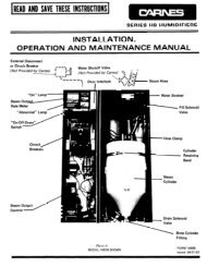
True Touchscreen Control Display<br />
FRONT PANEL DISPLAYS &<br />
CONTROLS<br />
The display on the front panel of the<br />
humidifier cabinet contains the “On-<br />
Off Drain” switch, the LCD True<br />
Touchscreen display and the “Fill”,<br />
“Drain” and “High Water” LED's.<br />
“ON-OFF-DRAIN” SWITCH<br />
In the “On” position the humidifier<br />
will operate if all controls are calling<br />
for humidity. The “Off” position is<br />
used for seasonal shut down if<br />
desired. The “Drain” position is<br />
used to drain water from the steam<br />
cylinder for maintenance. The fill<br />
solenoid valve will be on whenever<br />
the drain is activated to reduce the<br />
drain water temperature.<br />
LCD TRUE TOUCHSCREEN DISPLAY<br />
This LCD True Touchscreen display offers the necessary interface to<br />
control and monitor many aspects of the humidifier. On the home<br />
screen is the current steam output in Lbs./Hr. (or Kg/Hr). To select<br />
either is available in the settings menu. A “Service Required”<br />
indicator and button outlining current service issues, indicators for the<br />
four basic controls necessary for operation (control humidistat, high<br />
limit humidistat, air flow switch and door interlock), and various<br />
buttons which navigate to other menu pages when pressed are also<br />
available on the home page screen. The menu pages and their<br />
capabilities are detailed further in “True Touchscreen Menu Pages”<br />
section of this document.<br />
“FILL” LED<br />
The FILL LED is a blue light illuminated when the Fill Valve is<br />
activated. An activated Fill Valve allows water to flow into the cylinder<br />
of the humidifier. An analogous indicator, and a description of its<br />
operation, is offered in the “Component Activity” menu.<br />
“DRAIN” LED<br />
The DRAIN LED is a red light illuminated when the Drain Valve is<br />
activated. An activated Drain Valve allows water to drain from the<br />
humidifier. An analogous indicator, and a description of its operation,<br />
is offered in the “Component Activity” menu.<br />
“HIGH WATER” LED<br />
The HIGH WATER LED is an orange light illuminated when the High<br />
Water Sensor is activated. An activated High Water Sensor indicates<br />
that the water has risen to the maximum allowable level in the<br />
cylinder. This can be a normal situation, particularly if the cylinder is<br />
being filled with mostly unconditioned water. An activated High Water<br />
Sensor can also be a sign that the cylinder is close to end-of-life and<br />
needs replacing, or, in rarer cases, the cylinder is not conductive<br />
enough for the fresh water entering the humidifier. An analogous<br />
indicator, and a description of its operation, is offered in the<br />
“Component Activity” menu. More information on troubleshooting<br />
High Water situations can also be found through the “Help” menu on<br />
the home screen.<br />
HUMIDIFIER TRUE TOUCHSCREEN MENU PAGES<br />
The humidifier True Touchscreen user interface uses color<br />
conventions to help the user navigate the controls. The colors of<br />
different buttons indicate the following.<br />
1. Gray — Dim LCD is the only gray button. More<br />
information is available in the “home” page description.<br />
2. Orange — Orange buttons represent<br />
the object or subject described across the<br />
button. Most orange buttons have an indicator next to them, which<br />
can change in color, e.g. green, yellow or gray. Pressing orange<br />
buttons will bring you to a page which describes the object or subject<br />
in question.<br />
3. Yellow — Yellow buttons navigate a user to a new page<br />
dedicated to a set of functions. For example, the “Humidistat<br />
Demand” button brings the user to a page that shows what percentage<br />
demands both the Control and High Limit Humidistats are<br />
currently requesting, and details their functions. The bottom of each<br />
page, other than the home screen, has a square “Back” or “Home”<br />
button dedicated to directing the user back to their previous page.<br />
4. White — White buttons are used for confirming or<br />
entering data into the touchscreen. For example, they<br />
are used to confirm a change to the “Max Output”<br />
parameter, or entering a password to access the “Settings” menu.<br />
5. Maize — Help buttons are used<br />
exclusively in the “Help” page. These<br />
help buttons answer frequently asked questions about the operation,<br />
maintenance and troubleshooting of the humidifier. It is also a<br />
convenient place to look at humidifier electrical data when an IOM is<br />
not available.<br />
“HOME” PAGE<br />
The home page is the main screen through<br />
which most other pages can be accessed.<br />
The large blue square to the left shows the<br />
steam output. The orange and yellow<br />
buttons on the home page are considered<br />
“Operational & Status” indicators. Touching<br />
any of these displays will show dialog<br />
explaining the subject or status of that button. The orange buttons also<br />
have indicator boxes to the left showing actual status. Green shows<br />
ready to operate.<br />
1. Dim LCD (gray) - As a power saving feature, pressing the Dim<br />
LCD button will shut the backlight of the LCD off. Once off,<br />
pressing anywhere on the True Touchscreen will turn the<br />
backlight on. The humidifier can also automatically turn off the<br />
backlight after 15 minutes. See the “Settings” page for more<br />
information on enabling/disabling the Auto-Dim feature.<br />
2. Humidistat Demand (yellow) - Brings the user to a page that<br />
shows what percentage demands both the Control and High<br />
Limit Humidistats are currently requesting, and further details<br />
their functions.<br />
3. Component Activity (yellow) - Button lists the internal<br />
components used in the humidifier. Their respective indicators<br />
showing whether the components are activated or not. From<br />
this page, the user can view more information on the<br />
components and their functions.<br />
4. Setpoints (yellow) - The three setpoints of the unit are listed on<br />
this page. The setpoint is the target Lb./Hr. output of the<br />
humidifier.<br />
5. Settings (yellow) - Any settings of the humidifier, e.g. Max<br />
Output, Timers or Fan Speed, can be accessed through this<br />
page. This page is password protected. For more information,<br />
refer to the “Settings” page section.<br />
6. Help (yellow) - Frequently asked questions about the humidifier<br />
can be answered through the Help page. It is a convenient<br />
resource to resolve many issues quickly and effectively.<br />
7. Service Required (orange) - Invokes a page that describes<br />
what service is needed by the humidifier, if any. Indicator light to<br />
the left of the button turns red when service is needed, and will<br />
otherwise remain green. Refer to the separate “Service<br />
Required” page for more information.<br />
8. Steam (orange) - Explains the status of the “Steam”<br />
indicator light. The humidifier will only produce steam if the<br />
“Steam” indicator light is green. The indicator will be brown<br />
when the On/Off/Drain switch is in the “Off” position. It will turn<br />
yellow if the switch is in the “On” position, but one or more of the<br />
four basic controls are not satisfied (Control Humidistat, High<br />
Limit, Air Flow, Door Interlock). The light will turn green if all of<br />
the above switches and controls are satisfied.<br />
9. Control Humidistat (orange) - Explains the status of the<br />
Control Humidistat indicator light, and also shows the current<br />
demand of the Control Humidistat.<br />
10. High Limit Humidistat (orange) - Explains the status of the<br />
High Limit Humidistat indicator light, and also shows the current<br />
demand of the High Limit Humidistat.<br />
11. Air Flow (orange) - Explains the status of the Air Flow switch.<br />
12. Door Interlock (orange) - Explains the status of the Door<br />
Interlock switch.
Quality Built Products Since 1939<br />
Vents &<br />
Fans<br />
VAV<br />
Terminals<br />
Registers, Grilles<br />
& Diffusers<br />
Louvers & Penthouses<br />
Energy<br />
Recovery<br />
Fire & Smoke<br />
Dampers<br />
<strong>Humidifier</strong>s<br />
448 South Main Street<br />
P.O. Box 930040<br />
Verona, WI 53593-0040<br />
Ph: 608-845-6411<br />
Fax: 608-845-6504<br />
Email: carnes@carnes.com<br />
WWW.CARNES.COM