IO&M HB Steam Humidifier - "B" Design Series
IO&M HB Steam Humidifier - "B" Design Series
IO&M HB Steam Humidifier - "B" Design Series

You also want an ePaper? Increase the reach of your titles
YUMPU automatically turns print PDFs into web optimized ePapers that Google loves.
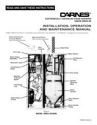
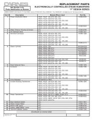
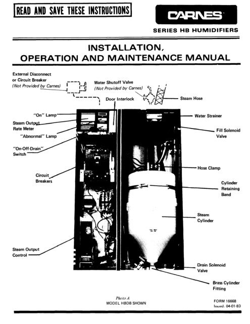
ELECTRICALCONNECTIONSPOWER MUST BE OFF BEFORE MAKING ANYELECTRICAL CONNECTIONSCheck unit electrical characteristics on label onoutside of cabinet. It must agree with the powerprovided to the unit, If it does not, contact yourCarnes representative.1. Remove screws securing electrical cover panelfor access to wiring (Photo D).2. Remove perforated access panel on top ofunit (Photo C).4. A fused disconnect or circuit breaker not providedby Carnes, MUST be installed per localand national electrical codes. See Table 2 forrecommended circuit ratings. The circuitbreaker switch in the humidifier is NOT foruse as a disconnect switch.5. An opening is provided on the top of theelectrical section (Photo C). Bring electricpower wires thru this opening and connect toelectric power terminals (Photo E).6. Replace electrical cover panel.Electrical Cover PanelModel <strong>HB</strong>DB ShownTABLE 2Photo DRECOMMENDED CIRCUIT RATINGS INAMPERESVOLTAGEMODEL 120 206 230 277 460 550 6003. Connect cabinet ground terminal to an independentground (Photo E). DO NOTuse the neutral ot a four-wire power supply.Photo ECONTROL CONNECTIONS1. A 7/8” opening is provided on the top of thecabinet. The control wiring should passthrough the opening to the terminal strip(Photo C). Note: A built-in transformerprovides 24.volt power for the control circuit.No outside power supply is requiredfor the control circuit.2. When the humidistat completes the circuitbetween the humidifier terminal strip, thehumidifier will operate. Wire any auxiliarycontrols such as high limit humidistat or airflow switch in series with the humidistat.3. Replace perforated access panel.6
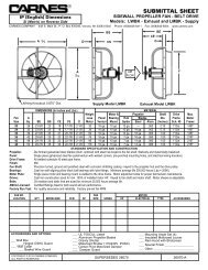
OPERATIONWhile the external disconnect switch is off, besure terminal connectors are firmly secured to thetop of the cylinder.1. Open all water supply valves external to unit.2. Turn external disconnect switch to “On”position.3. Turn circuit breaker(s) to “On” position.4. For safety, door interlock disconnects powerto cylinder(s) when door is open. <strong>Humidifier</strong>may be operated for service purposes whendoor is open by pulling out white button locatednext to “ON-OFF-DRAIN” switch.CAUTION: HIGH VOLTAGES ARE PRESENT.5. Turn “On-Off-Drain” switch to “On” position.Green “On” light should now be on.6. Unit will now be in operation if humidistatis calling for humidity. If humidistat is notcalling for humidity, adjust humidstat controlupward to check operation.7. When humidistat is calling for humidity waterwill slowly flow into cylinder. <strong>Steam</strong> outputmeter will slowly rise as water enters cylinder.8. The “Abnormal” light will remain on untilsufficient water has entered cylinder to provide50% to 75% of set output.Note: Unit has been preset at factory formaximum output as shown by red line onsteam output meter.9. When full output is reached the fill solenoidvalve will close.Note: When starting unit with new cylinderthe “Abnormal” light may come on and thedrain solenoid valve and contactor may openfor brief periods until water has come to fullboil.10. <strong>Humidifier</strong> will now cycle ON and OFF inresponse to humidistat. Drain solenoid valvewill periodically open to drain small quantityof mineral enriched water from cylinder.ADJUSTINGSTEAM OUTPUT RATE<strong>Steam</strong> output is regulated by adjusting steam outputcontrol (Photo H).To change steam output:1. Drain water from cylinder by turning “On-Off-Drain” switch to “Drain” position.2. Loosen lock nut on steam output control.3. Turn steam output rate control fully clockwise.4. Turn “On-Off-Drain” switch to “On” position.<strong>Steam</strong> output rate will gradually increaseas shown on steam output rate meter.When desired output is reached, slowly adjustuntil inlet water valve closes and stops incomingwater.5. Tighten lock nut on steam output control.If water boils above line 10 (on cylinder) severalhours after startup of humidifier or installation ofnew cylinder, order next lower size model cylinderwhen replacing. If water boils below line 3 onModels <strong>HB</strong>AB & <strong>HB</strong>DB or below line 0 on Models<strong>HB</strong>GB, <strong>HB</strong><strong>HB</strong> and <strong>HB</strong>JB order one higher sizemodel cylinder when replacing.<strong>Steam</strong> Output ControlPhoto FPhoto G7
MAINTENANCENote: It is advisable to inspect the humidifier visually atapproximately two week intervals.UNIT MAINTENANCE1. For safety, door interlock disconnects power to cylinder(s)when door is open. <strong>Humidifier</strong> may be operatedwhen door is open by pulling out white button locatednext to “ON-OFF-DRAIN”switch. CAUTION: HIGHVOLTAGES ARE PRESENT.2. Green “On” light should be on whenever power is suppliedto the humidifier, and “On-Off-Drain” switch is in“On” or “Drain” position. If green light is not on,check the following items:3.a. Circuit breakers must be in “On” position.b. Check each incoming power wire for proper voltageas shown on humidifier rating plate. CAUTION:HIGH VOLTAGES ARE PRESENT.c. Check green “On” light bult (24 volt) using voltmeter.When amber “Abnormal” light is continually on checkthe following items: (NOTE: Abnormal light will occasionallybe on for short periods during operation suchas start-up and whenever switch is in “Drain” position).a.b.C.d.e.f.9.Clean water strainer.All valves in water supply must be open and waterpressure above 20 psi.Check drain to be sure water is not constantly draining.Disassemble and clean drain valve if necessary.Replace cylinder if incoming water is flowing continuallybut desired output cannot be reached.Check each incoming power wire for proper voltageas shown on humidifier rating plate. CAUTION:HIGH VOLTAGES ARE PRESENT.Check voltage at fill solenoid valve. Replace valve if24 volts are present but valve is not open.Check steam hose for any restriction.CLEANING1. Turn “ON-OFF-DRAIN”2.3.4.5.6.7.8.WATER STRAINERTurn circuit breakers to “Off”.switch to “Off”.Shut off water supply valve ahead of unit.Remove brass nut by turning counter-clockwise. (Asmall amount of water will drain when nut is removed.Use small container to catch this water).Rinse strainer screen to remove deposits.Replace screen, nut, and gasket in strainer housing.Turn water supply on - check for leakage.Turn Circuit breakers to “On”.9. Turn “On-Off-Drain” switch to “On”.CHANGING STEAM CYLINDERNOTE: On two and three cylinder models all cylindersmust be replaced at the same time.1.2.3.4.5.8.9.10.12.13. Turn “On-Off-Drain”14.Turn”ON-OFF-DRAIN”switch to “Drain”. Completelydrain cylinder.Turn circuitbreakers to “Off”.Slip off cylinder terminal connectors.Remove steam hose.Loosen cylinder retaining band.6. For Models <strong>HB</strong>AB and <strong>HB</strong>DB remove cylinder by turningcylinder counter clockwise. For Models <strong>HB</strong>GB,<strong>HB</strong>H8 & <strong>HB</strong>JB remove cylinder by lifting it from thecylinder holder.7. Models <strong>HB</strong>AB and <strong>HB</strong>DB apply teflon tape or pipedope to the threaded portion of new cylinder. Models<strong>HB</strong>GB, <strong>HB</strong><strong>HB</strong> and BHJB remove the “0” ring whichmay have remained in the holder and clean the “0”ring seat in the holder.Models <strong>HB</strong>AB and <strong>HB</strong>DB screw cylinder into brasscylinder fitting. Models <strong>HB</strong>GB, <strong>HB</strong><strong>HB</strong> and <strong>HB</strong>JB makesure new “0”ring is on cylinder base and insert cylinderinto holder with enough pressure to seat “0” ring inholder.Tighten cylinder retaining band.Replace steam hose and tighten clamp.11. Replace terminal connectors on Models <strong>HB</strong>AB and<strong>HB</strong>DB in any sequence. On Models <strong>HB</strong>GB, <strong>HB</strong><strong>HB</strong> and<strong>HB</strong>JB match the numbers on the terminal connectorswith the numbers on the cylinders.Turn circuit breakers to “On”.switch to “On”.“Abnormal” light will remain on until water fillscylinder.After replacing humidifier cylinder, order a replacementimmediately. This will insure having a spare cylinder onhand when the next change is required.MISCELLANEOUSIf humidification is not going to be required for a longperiod of time, e.g. during summer cooling cycle in acomfort application, it is recommended the steam cylindersbe completely drained before switching off power andclosing water supply valve.-3 @ A Division of u Wehr Corporation448 SOUTH MAIN STREET, VERONA, WISCONSIN 53593Phone: (608) 845-6411 Telex: 265-410 Cable: CARNES