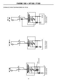
SKIDDING WINCH JL 601 - Farmi Forest
SKIDDING WINCH JL 601 - Farmi Forest
SKIDDING WINCH JL 601 - Farmi Forest

You also want an ePaper? Increase the reach of your titles
YUMPU automatically turns print PDFs into web optimized ePapers that Google loves.
FROM MACHINE:<br />
03121060 D-EN-230108-ER<br />
OPERATION, MAINTENANCE<br />
AND SPARE PARTS MANUAL<br />
<strong>SKIDDING</strong> <strong>WINCH</strong><br />
<strong>JL</strong> <strong>601</strong><br />
READ THIS OPERATION AND MAINTENANCE MANUAL CAREFULLY<br />
BEFORE USING THE MACHINE<br />
<strong>Farmi</strong> <strong>Forest</strong> Corporation<br />
Ahmolantie 6<br />
FIN-74510 Iisalmi, Finland<br />
Tel. +358 (0)17 83 241<br />
Fax. +358 (0)17 8324 372
<strong>JL</strong> <strong>601</strong><br />
WARNING SYMBOLS IN THIS MANUAL<br />
!<br />
DANGER!<br />
• imminent danger which could cause serious personal injury or death<br />
!<br />
WARNING!<br />
• danger which could cause personal injury<br />
!<br />
CAUTION!<br />
• conditions or misuse that could damage equipment or machinery<br />
NOTE!<br />
• reminders, such as for performing checks or carrying out<br />
maintenance or repair procedures<br />
INTRODUCTION<br />
This manual includes the information and maintenance instructions required for operating<br />
the machine in the optimal manner.<br />
Although you have experience in using this kind of machinery, read the operation and maintenance<br />
<br />
<br />
!<br />
CAUTION!<br />
Each and every operator must read, understand, and follow all safety<br />
instructions and procedures.<br />
CUSTOMER FEEDBACK<br />
We are happy to receive your opinions and suggestions for improvements by mail, fax or e-mail. All<br />
implemented suggestions for improvements will be rewarded.<br />
2
<strong>Farmi</strong> <strong>Forest</strong> Corporation<br />
Ahmolantie 6, FIN-74510 IISALMI, Finland<br />
<strong>JL</strong> <strong>601</strong><br />
MANUFACTURER’S DECLARATION OF<br />
CONFORMITY<br />
Informs that the machine, launched on to the market<br />
<strong>Farmi</strong> skidding winch<br />
(make)<br />
<strong>JL</strong> <strong>601</strong><br />
(type)<br />
(serial number)<br />
conforms to the directives 98/37/EC and 89/336/EC, as amended, and the national regulations<br />
bringing these directives into force.<br />
<br />
EN 292-2, EN 294, EN 60204-1<br />
<br />
prEN 1553<br />
Iisalmi, Finland 23.1.2008<br />
(place)<br />
(date)<br />
Juha Hallivuori<br />
3
<strong>JL</strong> <strong>601</strong><br />
TABLE OF CONTENTS<br />
SAFETY INSTRUCTIONS 5<br />
STICKERS AND PLATES 9<br />
MAIN PARTS AND ACCESSORIES 12<br />
TECHNICAL SPECIFICATION 13<br />
MOUNTING 14<br />
PRE-OPERATION CHECKS 15<br />
CONTROLS 16<br />
OPERATION 16<br />
PRE-OPERATION CHECKS 17<br />
<strong>WINCH</strong>ING 18<br />
<strong>SKIDDING</strong> 18<br />
DROPPING THE LOAD 19<br />
TRANSPORTATION 19<br />
MAINTENANCE 20<br />
LUBRICATION 20<br />
CLUTCH ADJUSTMENT 20<br />
ADJUSTING THE ROLLER CHAIN TIGHTNESS 21<br />
ADJUSTING THE DRUM BRAKE 21<br />
REMOVING THE <strong>WINCH</strong> MECHANISM 21<br />
ASSEMBLY OF THE MECHANISM 22<br />
TROUBLE SHOOTING 23<br />
FRAME 24<br />
MACHINERY 26<br />
ACCESSORIES 30<br />
CABLE WINDER PLL600 32<br />
COVER OF THE UNIVERSAL SHAFT 32<br />
Thread Millimeter Inch<br />
M6 10 7/16<br />
M8 13 1/2<br />
M10 17 11/16<br />
M12 19 3/4<br />
M16 24 15/16<br />
M20 30 1 3/16<br />
M24 34 1 7/16<br />
When ordering spare parts, please indicate the machine’s type from the machine plate,<br />
spare part’s order number, description and quantity required.<br />
Example. <strong>JL</strong><strong>601</strong>, 92820190, pin, 2 pc<br />
4
<strong>JL</strong> <strong>601</strong><br />
SAFETY INSTRUCTIONS<br />
These safety instructions are meant for the owners<br />
of FARMI equipment, as well as those who operate,<br />
service or repair it.<br />
The instructions help with:<br />
!<br />
CAUTION!<br />
Written authorization<br />
must be requested from the<br />
manufacturer for any<br />
alterations to the machine.<br />
•<br />
•<br />
using the machine safely, appropriately and<br />
effectively.<br />
identifying, avoiding and preventing potentially<br />
dangerous situations.<br />
The manufacturer supplies an instruction manual,<br />
which must always be available at the place of<br />
operation of the machine. Each user must read the<br />
safety, maintenance and operating instructions before<br />
operating the machine, and comply with these<br />
instructions at all times.<br />
Ensure that every operator of the machine is<br />
familiar with the content of the instruction<br />
<br />
instructions, and has been suitably trained<br />
before operating the machine.<br />
The machine complies with technical requirements<br />
and applicable safety regulations. However, incorrect<br />
use, maintenance or repair of the machine may<br />
cause risks.<br />
In addition to the instruction manual, remember to<br />
comply with regulations of the local occupational<br />
health and safety authorities, and with your<br />
country’s laws and decrees.<br />
The manufacturer is not liable for damages<br />
caused by:<br />
•<br />
•<br />
•<br />
•<br />
•<br />
incorrect, negligent or inappropriate use of the<br />
product.<br />
non-original spare parts.<br />
normal wear and tear.<br />
misuse caused by an untrained person’s<br />
improper actions.<br />
alterations made without the manufacturer’s<br />
permission.<br />
STARTING<br />
•<br />
•<br />
•<br />
•<br />
•<br />
•<br />
•<br />
•<br />
•<br />
•<br />
•<br />
•<br />
•<br />
•<br />
Familiarize yourself thoroughly with the use,<br />
operation and controls of the machine and its<br />
equipment before starting.<br />
Familiarize yourself with the capacities and<br />
limitations of the machine and its equipment.<br />
Do not use the machine unless you are<br />
completely familiar with its operation.<br />
Be aware of the machine’s danger zones.<br />
During operation, prevent bystanders from<br />
entering the danger zone.<br />
Ensure that each operator has the necessary<br />
safety equipment, such as a helmet, safety<br />
goggles, work safety boots and suitable protective<br />
clothing.<br />
Never wear loose clothing around moving parts.<br />
Protect long hair!<br />
Ensure that work is carried out according to the<br />
stipulations of applicable occupational health<br />
and safety legislation.<br />
Before starting up or using the machine, ensure<br />
that it cannot cause a risk to other people or<br />
property.<br />
Perform a safety check on the machine before<br />
every use. If you observe any faults or<br />
<br />
Before operating the machine, ensure that there<br />
are no foreign articles in it.<br />
Place the machine on a hard, level surface for<br />
operation. In the winter avoid working in slippery<br />
areas.<br />
Before operation, ensure the machine is properly<br />
connected.<br />
<br />
5
<strong>JL</strong> <strong>601</strong><br />
OPERATION<br />
MAINTENANCE<br />
•<br />
•<br />
•<br />
•<br />
•<br />
•<br />
•<br />
•<br />
•<br />
•<br />
•<br />
•<br />
!<br />
DANGER!<br />
Many occupational accidents<br />
take place in abnormal<br />
circumstances. Therefore it is<br />
important to take into account<br />
all the possible circumstances<br />
that may arise during operation<br />
of the machine.<br />
Depending on the machine’s type, it will have<br />
diverse safety devices and protectors. These are<br />
meant to protect the machine and its operator,<br />
and they must never be removed or altered.<br />
Never start up or use the machine without all<br />
the safety devices and protectors in place. Also<br />
check the universal joint’s safety equipment and<br />
joins.<br />
Never insert any body part into the machine with<br />
the engine running.<br />
If any faults arise that may jeopardize occupational<br />
safety, turn off the machine.<br />
During operation, the machine’s operator is<br />
responsible for safety in the whole work area.<br />
Work may not be carried out in the presence of<br />
any factors that jeopardize occupational safety.<br />
Exercise extreme caution when hitching /<br />
unhitching the machine from a tractor/trailer.<br />
CAUTION!<br />
The machine’s operator must<br />
!<br />
have constant, unobstructed<br />
visibility of the work area. If<br />
this is not possible, the ope-<br />
CAUTION!<br />
rator must work with an assistant.<br />
Look out for moving parts when the machine is<br />
in operation.<br />
Secure the machine against unauthorized and<br />
accidental operation (e.g. moving when parked)<br />
whenever it is left unattended.<br />
Never leave the machine running unattended.<br />
Avoid causing fast, stroke-like loading.<br />
Never exceed the given operating values.<br />
All safety and warning signs on and in the<br />
machine must be legible and intact.<br />
The machine may not be operated by persons<br />
<br />
or alcohol.<br />
6<br />
•<br />
•<br />
•<br />
•<br />
•<br />
•<br />
•<br />
•<br />
•<br />
•<br />
The machine may only be serviced and repaired<br />
by professionals.<br />
Electrical and hydraulic faults may only be<br />
repaired by authorized professionals.<br />
In cases requiring welding, contact<br />
the manufacturer.<br />
Turn off the tractor engine and disconnect the<br />
universal joint before beginning service or<br />
maintenance actions.<br />
Ensure that there is no pressure in the hydraulic<br />
system.<br />
Take out the key from the tractor’s ignition for<br />
the duration of the servicing or maintenance.<br />
Check that the power is off from the machine<br />
you are working on.<br />
When servicing the machine, place it on a level<br />
surface and ensure that it cannot be moved.<br />
Observe the service intervals and annual safety<br />
inspections.<br />
<br />
manufacturer’s requirements. This can be<br />
guaranteed by using original parts.<br />
Put all safety devices back into place immediately<br />
once servicing or maintenance is complete.<br />
When lifting the machine,<br />
check that the lifting/hoisting<br />
equipment is in perfect<br />
working order. Check the<br />
weight of the machine before<br />
lifting it. Choose lifting<br />
trajectories so that they do not<br />
cause any danger.<br />
<br />
hoisting cables and hoists. Always comply with local<br />
safety regulations.<br />
OILS AND LUBRICATION<br />
•<br />
•<br />
•<br />
•<br />
!<br />
Always use the oil types recommended by the<br />
manufacturer. Other types of oil may cause<br />
faults or improper operation of the equipment,<br />
which could lead to serious damage to people or<br />
property.<br />
Never mix different liquids or oils.<br />
Always follow the manufacturer’s lubrication<br />
instructions.<br />
Use control equipment carefully until the hydraulic<br />
oil has had time to reach its operating temperature.
<strong>JL</strong> <strong>601</strong><br />
SAFETY INSTRUCTIONS<br />
FOR HYDRAULIC CIRCUITS<br />
1.<br />
2.<br />
3.<br />
4.<br />
5.<br />
6.<br />
7.<br />
8.<br />
9.<br />
10.<br />
11.<br />
12.<br />
13.<br />
Work on hydraulic equipment may only be<br />
carried out by professional hydraulic engineers.<br />
Be cautious when using the equipment in cold<br />
conditions.<br />
Check the machine for leaks. Do not use the<br />
machine if there is a leak from any system.<br />
Check all hydraulic hoses – particularly those<br />
which are bent during use – and replace any<br />
that are in poor condition or have leaks. Ensure<br />
that all joins are tight and that the lines are not<br />
damaged. Check that all protective caps and<br />
<br />
Check that all hose connectors, lengths and<br />
qualities comply with applicable requirements.<br />
When replacing or repairing hoses, use original<br />
parts or hoses and connectors recommended<br />
by the manufacturer. Check particularly that the<br />
pressure classes of the hoses and connectors<br />
are suitable to the operating pressure levels.<br />
Check that all safety devices such as pressure<br />
relief valves, etc., are in place and work properly.<br />
Familiarize yourself with their use.<br />
Safety systems may never be bypassed.<br />
Check the main hydraulic parts daily, and<br />
always after a fault. Replace any damaged<br />
parts immediately.<br />
If a component is damaged, clean it before<br />
repairing it. Do not use solvents when cleaning<br />
parts.<br />
Do not attempt to carry out repairs that you are<br />
not fully familiar with.<br />
Never carry out repairs of the hydraulic circuit<br />
when the system is pressurized. When<br />
pressurized, the oil spray can penetrate the skin<br />
and cause mortal danger.<br />
Never work below a device or component that is<br />
only being held up by hydraulics.<br />
Use separate supports when carrying our<br />
maintenance or repairs. Do not disconnect<br />
cylinders or their valves until the machine is well<br />
supported.<br />
Most hydraulic oils do not evaporate easily. Risk<br />
factors include hot oil, spills and oil mist<br />
(pressurized).<br />
If oil gets into your eyes, rinse with plenty of<br />
water and contact a doctor.<br />
Avoid prolonged or repeated contact with your<br />
skin.<br />
14. If sprays or contact with the skin cannot be<br />
avoided, use protective gloves, goggles and<br />
clothing as necessary. Do not use oily clothing.<br />
15. Avoid discharging hydraulic oil into the<br />
environment, as it can pollute waterways and<br />
the groundwater. When working in ecologically<br />
vulnerable areas, use biofuel.<br />
16. Store the oil in sealed containers provided by<br />
the manufacturer. Try to transfer the oil directly<br />
from its container into the tank.<br />
17. If the oil must be passed through other containers,<br />
ensure that they are completely clean. Caps,<br />
<br />
clean.<br />
18. Never store oil outdoors, as water could condense<br />
in it.<br />
19. Always dispose of oil in a suitable container,<br />
never into the environment!<br />
7
<strong>JL</strong> <strong>601</strong><br />
SAFETY INSTRUCTIONS FOR <strong>WINCH</strong>ES<br />
• Check that the wire cable is in good condition<br />
before using the winch (check for corrosion,<br />
sharp bends, breakage and thickness of<br />
strands). If a cable snaps, it can whip towards<br />
the operator or away from the winch.<br />
• Operate the winch with a guide cable at least 2<br />
meters away to the side of the machine. Do not<br />
operate the winch from the tractor cabin unless<br />
a safety net has been installed.<br />
• When winching downhill, the pulling must be<br />
done from the side using an additional idler.<br />
• When winching on a hill, do not follow the load<br />
from below.<br />
• Side-winching must not be done at angles of<br />
more than 30 degrees.<br />
• It is extremely dangerous to be in the space<br />
between a load attached to the wire cable and<br />
the winch.<br />
• Check that all bystanders are at a safe distance<br />
of at least 15 meters whenever the machine is<br />
running. Place warning signs on approaching<br />
roads.<br />
• Never touch the wire cable by hand during<br />
winching.<br />
• The maximum load must be adjusted to conditions.<br />
• Check that the winching chains are carefully<br />
attached. Do not attach the wire cable directly to<br />
the load.<br />
• <br />
fasteners and 2 for chain-type fasteners.<br />
• Disconnect the transmission before examining<br />
the machine in the case of any faults.<br />
• Ensure the wire cable is as short as possible<br />
during transport.<br />
• The winch may only be used for winching and<br />
hauling. Do not use the winch for lifting loads.<br />
8
<strong>JL</strong> <strong>601</strong><br />
STICKERS AND PLATES<br />
The following plates and labels must be correctly attached to the machine.<br />
Missing safety plates / labels must be replaced immediately.<br />
1<br />
8<br />
2<br />
5<br />
3<br />
3<br />
6<br />
4<br />
7<br />
2. Note! See manual for operation and<br />
maintenance. (41014750)<br />
1. Machine plate <strong>JL</strong><strong>601</strong> (41011980)<br />
9
<strong>JL</strong> <strong>601</strong><br />
STICKERS AND PLATES<br />
3. Nr 41014740<br />
Falling danger!<br />
Do not work in an oblique position.<br />
Crushing danger!<br />
Do not use the winch for the lifting.<br />
Watch out for a breaking cable!<br />
Always use the protective screen.<br />
4. Nr 41014730<br />
Note!<br />
Before doing maintenance work turn off the<br />
motor, remove the ignition key and disengage<br />
the P.T.O.<br />
Accident danger!<br />
Keep the safety equipment where it belongs.<br />
Winding danger!<br />
Do not wear too loose clothes and keep the hair<br />
bound inside the cap.<br />
10
<strong>JL</strong> <strong>601</strong><br />
STICKERS AND PLATES<br />
5. Nr 41014720<br />
Falling danger!<br />
Do not winch at sideways angles exceeding<br />
30 degrees.<br />
Crushing danger!<br />
Do not stand in front of the winch when working.<br />
Stand on the side at a distance of at least<br />
6 ft from the winch.<br />
Crushing danger!<br />
Do not winch downhill.<br />
6. Maximum rpm (42381474)<br />
7. METSÄ-sticker (43402070)<br />
43402070<br />
F<br />
A<br />
R<br />
M<br />
I<br />
30730501<br />
8. FARMI-sticker (30730501)<br />
11
MAIN PARTS AND ACCESSORIES<br />
<strong>JL</strong> <strong>601</strong><br />
Snatch block<br />
Control rope<br />
Clutch engagement lever<br />
Cable drum<br />
Upper diverting pulley<br />
Drive shaft<br />
Lower diveting pulley<br />
(optional)<br />
Cable<br />
(optional)<br />
Dozer blade<br />
<br />
12
<strong>JL</strong> <strong>601</strong><br />
TECHNICAL SPECIFICATION<br />
TECHNICAL SPECIFICATION<br />
Tractive power Cable drum empty ( Maximum)<br />
Cable drum full (Minimum)<br />
Cable capacity<br />
Ultimate strength of the cable 1,96 kNmm 2<br />
Winching speed 540 rpm<br />
Weight( without cable)<br />
Clutch<br />
Power transmission<br />
Mounting<br />
Power needed<br />
<strong>JL</strong><strong>601</strong><br />
60 kN<br />
27 kN<br />
130 m of ø 10 mm cable<br />
recommendation 100 m of ø 12 mm cable<br />
60 m of ø 14 mm cable<br />
0,56 - 1,26 m/s<br />
390 kg<br />
Mechanical friction plate clutch with heat sink<br />
Universal shaft from tractor<br />
To 3-point hitch(Kat.II)<br />
min. 45 kW (60 hp)<br />
DIMENSIONS<br />
900<br />
460<br />
800--1040<br />
1770<br />
2320<br />
1800<br />
750<br />
13
<strong>JL</strong> <strong>601</strong><br />
MOUNTING<br />
SHORTEN THE DRIVE SHAFT<br />
MOUNTING TO THE 3-POINT HITCH<br />
The winch can be mounted to the 3-point linkage<br />
of any tractor. Power transmission is obtained<br />
through universal shaft from tractor.<br />
!<br />
CAUTION!<br />
Both PTO halves must<br />
be shortened by equal<br />
amounts.<br />
ASSEMBLY OF THE PTO SHAFT<br />
A<br />
If the PTO shaft is too long<br />
it may get pressed when the<br />
three point hitch is lifted up.<br />
! This may cause damage to<br />
CAUTION!<br />
the bearings of the winch<br />
or to the PTO of the tractor.<br />
The PTO shaft must not be too short in any<br />
position.<br />
The PTO length is suitable, if the pipes do<br />
not reach the bottom.<br />
PTO is optional equipment.<br />
<br />
<br />
20<br />
A<br />
1.<br />
2.<br />
3.<br />
4.<br />
Mount the winch to the 3-point hitch of the<br />
tractor.<br />
Raise the winch high enough to get the PTO<br />
shaft of the tractor and the winch to a horizontal<br />
level.<br />
If you have a shortened PTO shaft available,<br />
put one end into the drive shaft and check that<br />
the distance of the locking of the other end.<br />
1 2<br />
Take into account the additional clearance of<br />
approx. 20 mm (0.78”).<br />
Fasten the other end of the PTO shaft in its<br />
place and also move the winch sideways at <br />
the same time securing that the axis does not • First cut the thicker cover to a correct lenght<br />
base.<br />
(1). Remember 20 mm (0.78”) clearance.<br />
Then cut away the same amount from the<br />
form pipe. Make a similar shortening to the<br />
second half of the PTO shaft. Remove the burr<br />
<br />
• Connect the PTO shafts within each other.<br />
Make sure by moving eevator carefully up and<br />
cient.<br />
Check that the axis have 20 mm (0.78”)<br />
latitude.<br />
14
<strong>JL</strong> <strong>601</strong><br />
FASTENING THE CABLE TO THE DRUM<br />
PRE-OPERATION CHECKS<br />
1.<br />
2.<br />
3.<br />
4.<br />
5.<br />
6.<br />
7.<br />
Tape the cable end to prevent loosening of the<br />
core wires.<br />
Pass the cable through the hole in cable<br />
guard, over the upper snatch block and then<br />
inside the winch.<br />
Insert the cable from behind the roll of the<br />
drum brake.<br />
Pull the cable onto the drum from the left hand<br />
side (the same side as the clutch lever).<br />
Pass the cable end through the hole in the<br />
drum plate, pull about 15 cm (6”), and insert<br />
under the wedge of the cable lock device. See<br />
<br />
Tighten the cable lock screw.<br />
Winch the cable on the drum. BUT REMEM-<br />
BER THAT THE CABLE HAS TO BE LOADED<br />
HEAVILY, WHEN <strong>WINCH</strong>ING THE CABLE<br />
BACK ON THE DRUM.<br />
CABLE<br />
Check that:<br />
•<br />
•<br />
•<br />
the cable is faultless (breakage risk).<br />
there are no twists or kinks (breakage risk) in<br />
the cable.<br />
the cable has been properly fastened to the<br />
winch.<br />
<strong>WINCH</strong><br />
Check that:<br />
•<br />
•<br />
•<br />
•<br />
•<br />
•<br />
all the pins and lynch pins are in place.<br />
all bolts and nuts have been tightened.<br />
roller chain is tight.<br />
the drum brake has been properly adjusted.<br />
the clutch has been correctly adjusted.<br />
lubrication is carried out correctly. See lubricating<br />
instructions.<br />
MOUNTING TO THE TRACTOR<br />
Check that:<br />
<br />
•<br />
•<br />
•<br />
•<br />
•<br />
the tractor’s top link point is locked. (with the<br />
help of a support, if necessary).<br />
the pins are properly secured.<br />
the sway bars or turnbuckles are suitably tight.<br />
the PTO-shaft is suitably long, properly fastened<br />
and the shield chains attached.<br />
the support leg of the winch is turned upward.<br />
Do not use longer cable than needed. With<br />
correct length you achieve good pulling strength<br />
and proper winding of the cable.<br />
15
<strong>JL</strong> <strong>601</strong><br />
CONTROLS<br />
!<br />
WARNING!<br />
PULLING OUT THE CABLE<br />
Get acquainted with the<br />
controllers of the winch before<br />
the use, tests the stopping<br />
functions of the winch<br />
and the tractor and all other<br />
functions. Each function has<br />
to be in perfect condition.<br />
OPERATION<br />
SAFETY PRECAUTIONS<br />
Read the operation<br />
instructions before<br />
operating this machine!<br />
! It is the owner’s<br />
WARNING! responsibility to instruct all<br />
equipment operators and<br />
support personnel in the operation of this<br />
winch.<br />
• The cable can be freely drawn out if the drum<br />
has not been locked with a latch.<br />
<strong>WINCH</strong>ING<br />
• The winch is equipped with a clutch, which will<br />
be used by the control rope. When the user<br />
draws the control rope, the winch begings to<br />
draw in the cable. Winching will stop when the<br />
rope is released.<br />
• The end of the cable drum is equipped with<br />
a friction clutch, which slips, if the load is too<br />
heavy. This prevents cable break or damages<br />
if the load gets caught.<br />
Control rope<br />
1.<br />
2.<br />
3.<br />
Choose a horizontal, hard based skidding route<br />
for the tractor. Avoid steep slopes,<br />
especially when winching from the side. Check<br />
that the winching trail is clear and that the<br />
tractor’s parking brake is on. Do not run the<br />
tractor at a high idle when winching.<br />
Maximum P.T.O speed is 540 rpm. Ensure that<br />
the logs can be drawn freely. Be especially<br />
careful when working on slopes.<br />
Avoid winching sideways at angles exceeding<br />
30 degrees. Use snatchblock which is fastened<br />
<br />
The safest place for the operator is at the back<br />
left side of the winch, allowing good visibility.<br />
<br />
the working area.<br />
The tractor must have a ROPS cab and front<br />
end weights.<br />
Latch rope<br />
• <br />
<br />
Avoid working in steep terrain. Ensure nothing<br />
is blocking the path of trees.<br />
• Avoid an unnecessarily strong pulls,<br />
the tractor may roll over.<br />
• Adjust the tractors rpm’s according to the<br />
conditions.<br />
• Use a shield between the seat and the winch<br />
(e.g. safety cab or protective screen) if you run<br />
the winch from the tractor seat.<br />
• Use agreed signals when working in groups.<br />
<br />
16<br />
4.<br />
When you use a light tractor, there is a very<br />
big risk that the tractor will roll over. To avoid<br />
that risk, you must add extra weight to the<br />
front of the tractor.
<strong>JL</strong> <strong>601</strong><br />
• The falling danger of the tractor can be<br />
reduced by winching through the lower<br />
snatchblock.<br />
PRE-OPERATION CHECKS<br />
MOUNTING AND USE OF THE LOWER<br />
SNATCHBLOCK<br />
<br />
<br />
<br />
• Usually the logs are winched in through the<br />
upper pulley of the winch. This lifts the logs<br />
and they dig less into the ground. The weight<br />
of the load also pushes the blade into the<br />
ground thus anchoring the winch and the<br />
tractor to the ground.<br />
• The winch has a lower snatchblock. The main<br />
use of the lower snatchblock is to lower the<br />
pulling point. This enables larger loads to be<br />
skidded out . For skidding out the load the<br />
cable is transferred to the lower snatchblock.<br />
• Several logs can be hooked up and winched<br />
in at one time by means of keyhole sliders on<br />
the cable. The skidding chain should have a<br />
pin on the end, which makes it easier to pass<br />
<br />
When using the lower<br />
snatch block make sure that<br />
it follows the direction of the<br />
!<br />
cable. Otherwise the cable<br />
CAUTION! will be damaged, when it is<br />
pressed between the snatch<br />
block and the lower snatchblock frame.<br />
!<br />
CAUTION!<br />
When wInching an unloaded<br />
cable, make sure that the<br />
<br />
with cable and doesn’t<br />
cause cable to crosscut.<br />
<br />
<br />
<br />
<br />
17
<strong>JL</strong> <strong>601</strong><br />
<strong>WINCH</strong>ING<br />
!<br />
CAUTION!<br />
Before using the winch,<br />
you have to pull the cable<br />
completely out of the drum<br />
and winch the cable back on<br />
the drum with a heavy load.<br />
Otherwise the cable will be<br />
damaged.<br />
4.<br />
heavier than the selected pull. This prevents<br />
damages to the cable or winch. Avoid extra<br />
large loads. The winding speed depends on<br />
the number of revolutions of the tractor. Do not<br />
wind too fast.<br />
Stop winching when the logs are at about<br />
1,5-3 m (5-10 ft) from the tractor. Install the<br />
cable on the lower snatch block.<br />
• Park the winch and tractor on level, stable<br />
ground. Lock the brakes of the tractor before<br />
winching. Lower the 3-point hitch so that the<br />
dozer blade anchors the winch to the ground.<br />
.<br />
!<br />
CAUTION!<br />
Do not let the dozer blade<br />
sink too deeply into the<br />
ground, so that the PTO<br />
shaft is not damaged.<br />
<br />
• Before using the skidding winch, make sure<br />
that the lower snatch block, the upper snatch<br />
<br />
<strong>SKIDDING</strong><br />
<br />
1.<br />
2.<br />
3.<br />
Draw the cable to the load but avoid twitches.<br />
Do not draw out too much cable to avoid loose<br />
spaces when the cable is reeled in.<br />
Start the tractor, turn the PTO on. Use the<br />
winch with the control rope and stand in a safe<br />
place at a distance of at least 2 m (6 ft) from<br />
the winch. Use the upper snatchblock when<br />
winching.<br />
<br />
clutch to avoid warming of the clutch. Stop<br />
winching by letting go of the control rope for<br />
the leave. The clutch will slip when the load is<br />
4.<br />
18<br />
<br />
1.<br />
2.<br />
3.<br />
Turn the P.T.O on. Pull the clutch control rope<br />
and winch the logs to the pulley. Keep the<br />
tension on the cable and pull the thinner rope<br />
that operates the brake ratchet. Stop pulling<br />
<br />
in place. Alternatively the skidding chains can<br />
be attached to the notched beam.<br />
Turn off the P.T.O.<br />
Raise the 3-point hitch so that the logs come<br />
<br />
Move the logs to the desired place.
<strong>JL</strong> <strong>601</strong><br />
IF YOU GET STUCK WITH THE TRACTOR<br />
1.<br />
2.<br />
<br />
Winch in the load.<br />
If you cannot move the tractor, release the<br />
load and winch the tractor out. When winching<br />
the tractor out, always run the cable under<br />
the lower pulley.<br />
<br />
WORKING IN ROUGH TERRAIN<br />
Drop the load before you reach bad terrain. Drive<br />
through the bad spot. Winch in the load again<br />
(Fig. 13.).<br />
<br />
DROPPING THE LOAD<br />
1.<br />
2.<br />
Let down the 3-point hitch.<br />
Pull the clutch rope until the brake ratchet<br />
releases, then stop pulling the clutch rope.<br />
The logs drop to the ground.<br />
WRONG<br />
TRANSPORTATION<br />
The cable should be run under lower snatchblock<br />
and locked in place for transportation of the<br />
winch.<br />
<br />
RIGHT<br />
19
<strong>JL</strong> <strong>601</strong><br />
MAINTENANCE<br />
CLUTCH ADJUSTMENT<br />
SAFETY<br />
!<br />
DANGER!<br />
LUBRICATION<br />
Disengage the P.T.O and turn<br />
the tractor off before you<br />
service the winch, remove<br />
the keys so the tractor cannot<br />
be started up accidentally.<br />
1.<br />
2.<br />
3.<br />
4.<br />
Loosen the nuts A and B at both ends of the<br />
drum axle. Wrench opening 1 7/16” (36 mm).<br />
Adjust the clutch by turning the axle C with<br />
9/16” or 14 mm wrench. The clutch tightens<br />
clockwise, loosens counterclockwise. Turn<br />
max. 1/4 turn.<br />
After adjustment retighten the nuts A and B on<br />
the ends of the drum axle.<br />
Pull the control rope. The lever should move<br />
up 1.5” (4 cm) before the clutch engages. If<br />
the clutch engages earlier loosen the clutch<br />
setting.<br />
!<br />
Do not oil the drive chain,<br />
because the oil will work its<br />
way to the clutch!<br />
CAUTION!<br />
The cable drum, main sprocket and snatchblock<br />
<br />
Following points require lubrication:<br />
A B C<br />
1.<br />
2.<br />
3.<br />
Grease the drum clutch parts after every 500<br />
working hours. Always use good quality lubrication<br />
grease.<br />
Grease the PTO-shaft regularly and aways<br />
<br />
Grease the drum chain lightly (not with oil)<br />
after every 50 working hours with spray type,<br />
hardening chain grease.<br />
Wipe off the excessive grease.<br />
<br />
Swing joints sideways for greasing<br />
8h<br />
8h<br />
When used in winter<br />
the guard tubes must<br />
be greased to avoid<br />
freezing.<br />
20h<br />
Apply grease inside the<br />
<br />
h= working hours<br />
<br />
20
<strong>JL</strong> <strong>601</strong><br />
ADJUSTING THE ROLLER CHAIN<br />
TIGHTNESS<br />
Roller chains tightness adjustment is carried out<br />
<br />
1.<br />
2.<br />
3.<br />
4.<br />
Loosen the two bolts holding the chain tightener<br />
(11/16” or 17 mm wrench).<br />
Adjust the chain tightness by moving the chain<br />
tightener towards or away from center.<br />
Tighten the nuts.<br />
Check that the chain tightener runs on the<br />
rollers.<br />
NOTE! Do not over tighten the chain.<br />
REMOVING THE <strong>WINCH</strong> MECHANISM<br />
The whole winch mechanism can be removed in<br />
one piece from the frame. To remove the winch<br />
mechanism from the winch (e.g. in order to change<br />
the roller chain) follow the instructions below:<br />
1.<br />
2.<br />
3.<br />
4.<br />
5.<br />
6.<br />
Park the winch on a level, stable ground so that<br />
it leans a little backwards.<br />
Remove the cable.<br />
de<br />
the drive shaft. Socket size 24 mm (15/16”).<br />
per<br />
edge of the cover plate. Socket size 24 mm<br />
(15/16”).<br />
<br />
the washer. Socket size 36 mm (1 7/16”)<br />
Pull out the winch mechanism. Weight 242,5 lbs<br />
(110 kg).<br />
Tighten<br />
Loosen<br />
C<br />
<br />
ADJUSTING THE DRUM BRAKE<br />
Adjust the drum brake so that it slows down the<br />
drum slightly while pulling out the rope. This will<br />
reduce risk of tangling and backlash.<br />
• To increase the braking effect tighten the<br />
<br />
braking effect loosen the adjustment bolt.<br />
A<br />
B<br />
<br />
<br />
Friction piece<br />
Lock nut<br />
Drum brake adjustment bolt<br />
21
<strong>JL</strong> <strong>601</strong><br />
ASSEMBLY OF THE MECHANISM<br />
Make sure that the both pressure bearings are<br />
installed in a correct position, that is, the bearing<br />
with bigger internal diameter should be facing<br />
<br />
position of the two clutch engagement halves is<br />
<br />
1.<br />
2.<br />
Place one of the clutch engagement halves<br />
on the working tble so that the handle is at 8<br />
o’clock position and the 3 slanted surfaces<br />
face up.<br />
Grease the 3 slanted surfaces with vaseline<br />
and place the 3 rollers on the bottom of the<br />
slanted surfaces so that the thin ends point<br />
towards the middle. The other clutch engagement<br />
half (without handle) has 3 slanted<br />
surfaces on one side and two holes drilled on<br />
<br />
<br />
on when the winch is assembled.<br />
3. Place one clutch engagement half (without the<br />
handle) so that the halves bottom out when<br />
the handle is at 8 o’clock position and the two<br />
<br />
Be careful, there is only one correct position!<br />
Tape the halves together so that htey will stay<br />
together when you mount them on the drum<br />
axle.<br />
4. Install a protective plate. Check the clutch<br />
adjustment.<br />
8<br />
8<br />
12<br />
6<br />
12<br />
6<br />
12<br />
6<br />
<br />
halves<br />
a)<br />
b)<br />
c)<br />
Race with smaller inside diameter<br />
Race with larger inside diameter<br />
Main sprocket<br />
Clutch engagement half<br />
Roller<br />
Clutch engagement half<br />
Front plate<br />
Wire drum<br />
Drum axle<br />
The race with the larger inside<br />
diameter is towards the drum<br />
<br />
The race with the larger inside<br />
diameter is towards the drum<br />
22
<strong>JL</strong> <strong>601</strong><br />
TROUBLE SHOOTING<br />
CONDITION POSSIBLE CAUSE REMEDY<br />
Hard to pull the cable out Drum brake is too tight. Loosen the drum brake. See<br />
instructionsfrom item ”Adjusting<br />
the drum brake”.<br />
Cable gets tangled on the drum.<br />
Cable too loose on the drum.<br />
The cable is pressed between<br />
loose loops.<br />
Loosen the pin and pull the<br />
cable from the reel with the<br />
help of a tractor. Reel the cable<br />
tightly back in with the help of<br />
the load.<br />
Cable develops kinks. Cable brake too loose Tighten the drum brake.Tighten<br />
cable on the drum by pulling out<br />
the cable and by winching with<br />
a heavy load.<br />
Roller chain comes off.<br />
Rattling sound<br />
<br />
Tractor slides backwards when<br />
winching<br />
Roller chain too loose, some<br />
part is broken or the aligning is<br />
incorrect.<br />
Roller chain too tight, some<br />
part is broken or the aligning is<br />
incorrect.<br />
Normal wear of the clutch.<br />
Minimum thickness of the clutch<br />
plates is 7 mm.<br />
Oil or grease in the clutch<br />
Clutch too loosely adjusted<br />
Parking brakes are not on.<br />
Dozer blade does not anchor the<br />
<br />
Check the aligment of the<br />
chain. Check possible damages.<br />
Adjust the roller chain, change<br />
if necessary. See chapter<br />
”Adjusting the roller chain”.<br />
Check the aligment of the<br />
chain. Check possible damages.<br />
Adjust the roller chain, change<br />
if necessary. See chapter<br />
”Adjusting the roller chain”.<br />
See chapter ”Clutch<br />
adjustment”<br />
Disassemble and clean the<br />
parts.<br />
Adjustment of the clutch. See<br />
chapter ”Clutch adjustment”<br />
Lock on the parking brakes.<br />
Lower the winch all way to the<br />
ground.<br />
23
<strong>JL</strong> <strong>601</strong><br />
FRAME<br />
10<br />
8<br />
9<br />
16<br />
2<br />
18<br />
10<br />
17<br />
14<br />
5<br />
20<br />
19<br />
5.1 5.3 5.6<br />
4<br />
1<br />
5.2<br />
5.5 5.4<br />
6<br />
13<br />
12<br />
11<br />
6.1<br />
8<br />
11<br />
FRAME 21<br />
3<br />
23<br />
22<br />
6.3<br />
6.6<br />
PROTECTIVE<br />
SCREEN-<br />
6.2 6.6<br />
6.5<br />
6.4<br />
6.9<br />
6.7 6.8<br />
24<br />
15<br />
7.1<br />
7
<strong>JL</strong> <strong>601</strong><br />
FRAME<br />
Part Order no Description Remarks Qty<br />
1 23400030 Frame 1<br />
2 92820190 Pin 2<br />
3 52842150 Ringsplint 2<br />
4 43401199 Support leg 2<br />
5 33120015 Diverting pulley complete 1<br />
5.1 33120023 Frame 1<br />
5.2 43120039 Diverting pulley incl. part 5.3 1<br />
5.3 54511241 Slotted sealed ball bearing 2<br />
5.4 43120088 Finger guard 1<br />
5.5 52856283 Pin 1<br />
5.6 52813235 Split pin 6X50 DIN94 ZN 1<br />
6 03035200 Lower diverting pulley complete 1<br />
6.1 23130206 Frame 1<br />
6.2 43120039 Diverting pulley 1<br />
6.3 54511241 Slotted sealed ball bearing 2<br />
6.4 43130210 Screw 1<br />
6.5 52062440 Screw M24X240 DIN931 10.9ZN 1<br />
6.6 52117249 Lock nut M24 DIN985 8ZN 2<br />
6.7 43401025 Adjusting bracket 1<br />
6.8 03403110 Locking device 1<br />
6.9 52200102 Washer M24 DIN126 58ZN 1<br />
7 33130071 Lower protective screen 1<br />
7.1 52060209 Screw M10X16 DIN933 88ZN 2<br />
8 52060233 Screw M10X30 DIN933 88ZN 2<br />
9 52200045 Washer M10 DIN126 58ZN 4<br />
10 52110046 Nut M10 DIN934 8ZN 2<br />
11 43401640 Cover 2<br />
12 43401215 Axle 2<br />
13 52813102 Split pin 4X20 DIN94 ZN 2<br />
14 42721050 Snatch block 1<br />
15 43020775 Snatch block complete 1<br />
16 54824115 Latch rope 3,5 m 1<br />
17 54824099 Clutch rope 5,0 m 1<br />
18 33130303 Protective screen 1<br />
19 52060050 Screw M6X40 DIN933 88ZN 2<br />
20 52117066 Lock nut M6 DIN985 8ZN 2<br />
21 43130137 Snatch block 1<br />
22 52842143 Cotter 5X10⁵ 2<br />
23 52401015 Grease nipple AR1/8 1<br />
25
<strong>JL</strong> <strong>601</strong><br />
MACHINERY<br />
6.1<br />
6.2<br />
6.3<br />
6<br />
6.4<br />
6.9<br />
6.3<br />
6.11 6.13 6.12 6.6<br />
6.7<br />
6.5<br />
6.10<br />
6.8<br />
37<br />
35<br />
32 42<br />
17<br />
29<br />
18<br />
30<br />
2<br />
14 16 15<br />
9<br />
31<br />
36<br />
19<br />
4<br />
20 9<br />
39<br />
38<br />
22<br />
4.2<br />
4.1<br />
31 27 34<br />
4.4<br />
4.3<br />
12<br />
11<br />
21<br />
5<br />
5.1<br />
5.2<br />
5.1<br />
41<br />
25<br />
25.2<br />
25.1 25.3<br />
8<br />
23<br />
36 39<br />
33<br />
28<br />
13<br />
40<br />
3<br />
10<br />
7<br />
24<br />
10<br />
42<br />
1<br />
26
<strong>JL</strong> <strong>601</strong><br />
MACHINERY<br />
Part Order no Description Remarks Qty<br />
1 23100010 Frame 1<br />
2 43100254 Front plate 1<br />
3 33100066 Axle 1<br />
4 43110700 Sprocket complete 1<br />
4.1 33100109 Sprocket 1<br />
4.2 54562053 Slide bearing 2<br />
4.3 42722744 Friction piece 8<br />
4.4 52830015 Rivet 16<br />
5 33100025 Drum complete 1<br />
5.1 54562053 Slide bearing 3<br />
6 43100478 Drum brake complete 1<br />
6.1 43100680 Frame 1<br />
6.2 43100690 Roll 1<br />
6.3 43190860 Bushing 2<br />
6.4 43100536 Axle 1<br />
6.5 42723197 Friction piece 1<br />
6.6 52060258 Screw M10X40 DIN933 88ZN 1<br />
6.7 52110046 Nut M10 DIN934 8ZN 1<br />
6.8 52117108 Lock nut M10 DIN985 8ZN 1<br />
6.9 52813094 Split pin 4X25 DIN94 ZN 1<br />
6.10 52200045 Washer M10 DIN126 58ZN 1<br />
6.11 52060514 Screw M10X20 DIN933 88ZN 2<br />
6.12 94624046 Torsion spring DU32,5 1<br />
6.13 43010412 Fastening 1<br />
7 43401750 Splined shaft 1<br />
8 43100437 Chain tightener 1<br />
9 54542063 Ball thrust bearing 2<br />
10 54511340 Slotted sealed ball bearing 2<br />
11 54642194 Cup spring 4<br />
12 43100155 Bushing 1<br />
13 42723163 Key 1<br />
14 32722779 Clutch half 1<br />
15 33100165 Clutch half 1<br />
16 40660235 Roll 3<br />
17 43100171 Clutch lever 1<br />
18 33100298 Drum cover 1<br />
19 94612082 Tension spring DU26 1<br />
20 54820840 Roller chain 1<br />
21 54820568 Chain link 1<br />
22 43100205 Drum lock latch 1<br />
27
<strong>JL</strong> <strong>601</strong><br />
MACHINERY<br />
6.1<br />
6.2<br />
6.3<br />
6<br />
6.4<br />
6.9<br />
6.3<br />
6.11 6.13 6.12 6.6<br />
6.7<br />
6.5<br />
6.10<br />
6.8<br />
37<br />
35<br />
32 42<br />
17<br />
29<br />
18<br />
30<br />
2<br />
14 16 15<br />
9<br />
31<br />
36<br />
19<br />
4<br />
20 9<br />
39<br />
38<br />
22<br />
4.2<br />
4.1<br />
31 27 34<br />
4.4<br />
4.3<br />
12<br />
11<br />
21<br />
5<br />
5.1<br />
5.2<br />
5.1<br />
41<br />
25<br />
25.2<br />
25.1 25.3<br />
8<br />
23<br />
36 39<br />
33<br />
28<br />
13<br />
40<br />
3<br />
10<br />
7<br />
24<br />
10<br />
42<br />
1<br />
28
<strong>JL</strong> <strong>601</strong><br />
MACHINERY<br />
Part Order no Description Remarks Qty<br />
23 43000678 Ring D65 1<br />
24 52230067 Circlip 35X2,5 DIN471 1<br />
25 43401900 Chain tightener lock complete 1<br />
25.1 43401910 Chain tightener lock 1<br />
25.2 52060944 Screw M10X60 DIN933 88ZN 1<br />
25.3 52110046 Nut M10 DIN934 8ZN 1<br />
26 52390820 Felt seal 1<br />
27 520<strong>601</strong>18 Screw M8x16 DIN933 88ZN 1<br />
28 520<strong>601</strong>34 Screw M8X40 DIN933 88ZN 1<br />
29 52062015 Screw M12X20 DIN933 88ZN 2<br />
30 52062023 Screw M12X30 DIN933 88ZN 4<br />
31 52062106 Screw M16X30 DIN933 88ZN 2<br />
32 52063278 Screw M20X35 DIN931 88ZN 2<br />
33 52062213 Screw M20X40 DIN933 88ZN 2<br />
34 52200235 Washer M8 DIN9021 58ZN 1<br />
35 52200052 Washer M12 DIN125 58ZN 4<br />
36 52200102 Washer M24 DIN126 58ZN 2<br />
37 52110053 Nut M12 DIN934 8ZN 4<br />
38 52110079 Nut M16 DIN934 8ZN 2<br />
39 52110103 Nut M24 DIN934 8ZN 2<br />
40 52117082 Lock nut M8 DIN985 8ZN 1<br />
41 52117108 Lock nut M10 DIN985 8ZN 2<br />
42 52117207 Lock nut M20 DIN985 8ZN 4<br />
29
<strong>JL</strong> <strong>601</strong><br />
ACCESSORIES<br />
LL<br />
HOF-4<br />
SV<br />
ASV<br />
ATP<br />
PLL<br />
TP14IH<br />
JK<br />
NK1<br />
NK45<br />
W2200<br />
LK<br />
30
<strong>JL</strong> <strong>601</strong><br />
ACCESSORIES<br />
Part Order no Description<br />
JK 351 03190469 Machinery 3,5 t<br />
JK 501 03010501 Machinery 5 t<br />
JK 501T 03010519 Machinery 5 t, with brake<br />
JK <strong>601</strong> 03100006 Machinery 6 t<br />
JK<strong>601</strong>T 03110005 Machinery 6 t, with brake<br />
ATP 500 33032012 Lower pulley D = 105 mm<br />
ATP 500T 33031378 Lower pulley D = 153 mm<br />
ATP 501 03032400 Lower pulley with frame, D = 105 mm<br />
ATP 501T 03032410 Lower pulley with frame, D = 153 mm<br />
ATP <strong>601</strong>T 03035200 Lower pulley with frame, D = 180 mm<br />
ATP650T 03402000 Lower pulley with frame, D = 180 mm<br />
W 2100 54807706 PTO-shaft, 14 kW<br />
W 2200 54807714 PTO-shaft, 24 kW<br />
W 2300 54821012 PTO-shaft, 34 kW<br />
W 2400 54823060 PTO-shaft, 47 kW<br />
Belt TP14 54713037 Belt for TP14<br />
TP14 IH 30118120 Self releasing pulley, max. 3,5 t, without belt<br />
LK2-TK10 54817077 Notched hook<br />
NK 1 42381558 Hook<br />
NK 45 54824370 Rope drum<br />
JK 208 54827019 Skidding chain L = 2,0 m<br />
JK 248 54827043 Skidding chain L = 2,4 m<br />
LL 2 54813159 Choker (cable 8-12 mm)<br />
LL 4 54813167 Choker (cable 14 mm)<br />
VAIJ D8 54824677 Cable, D = 8 mm, F = 44 kNm<br />
VAIJ D10 54824032 Cable, D = 10 mm, F = 63 kNm<br />
VAIJ D12 54824040 Cable, D = 12 mm, F = 90,7 kNm<br />
VAIJ D14 54824057 Cable, D = 14 mm, F = 123,5 kNm<br />
SV 300T 43181577 Protective screen<br />
SV 600T 33130303 Protective screen<br />
PLL 500 33031196 Cable winder (<strong>JL</strong> 501) D = 90 mm<br />
PLL 600 43120542 Cable winder (<strong>JL</strong> <strong>601</strong>/650) D = 90 mm<br />
ASV 400 43020502 Lower protective screen<br />
HOF-4 03151930 Hydraulic control, 2 cylinders<br />
HOF-4G 03151940 Hydraulic control, 2 cylinders<br />
HOF 501 03151280 Mounting kit<br />
HOF <strong>601</strong>T/650T 03151290 Mounting kit<br />
HOF ALP 55-85 03151920 Mounting kit<br />
31
<strong>JL</strong> <strong>601</strong><br />
CABLE WINDER PLL600<br />
1<br />
2<br />
4<br />
6 3 7 5<br />
Part Order no Description Remarks Qty<br />
43120542 Cable winder complete 1<br />
1 43120559 Frame 1<br />
2 43030790 Diverting pulley 1<br />
3 54511159 Slotted sealed ball bearing 2<br />
4 92823269 Pin 1<br />
5 52854585 Pin 25X100 1<br />
6 52813219 Split pin 6X40 DIN94 ZN 2<br />
7 52401015 Grease nipple AR1/8 1<br />
COVER OF THE UNIVERSAL SHAFT<br />
3 4 1 2<br />
Part Order no Description Remarks Qty<br />
1 43511780 Cover of the universal shaft 1<br />
2 43110920 Fastener 1<br />
3 520<strong>601</strong>00 Screw M8X12 DIN933 88ZN 2<br />
4 52200235 Washer M8 DIN9021 58ZN 2<br />
32
WARRANTY<br />
<strong>Farmi</strong> <strong>Forest</strong> Oy grants a 12-month warranty on all of its products, covering<br />
material and manufacturing faults. The warranty comes into effect on<br />
the product’s delivery date.<br />
The manufacturer is not liable for damages caused by:<br />
• misuse of the product<br />
• alterations or repairs made without the manufacturer’s permission<br />
• <br />
• non-original parts<br />
The warranty does not cover wearing parts.<br />
Send faulty parts, carriage paid, to the manufacturer for inspection. Repairs will<br />
be conducted by <strong>Farmi</strong> <strong>Forest</strong> Oy or an authorized expert. The warranty is valid<br />
<br />
within 14 days of receipt of the product.<br />
<br />
understood the instruction manual that came with the product.<br />
<strong>Farmi</strong> <strong>Forest</strong> Corporation<br />
Ahmolantie 6<br />
FIN-74510 IISALMI<br />
FINLAND
Date of delivery:_____/_____ 20_____<br />
Dealer:<br />
Dealer’s address:<br />
Dealer’s tel:<br />
Product and type:<br />
Serial number:<br />
Return to the manufacturer<br />
Date of delivery:_____/_____ 20_____<br />
Dealer:<br />
Dealer’s address:<br />
Dealer’s tel:<br />
Customer:<br />
Customer’s address:<br />
Customer’s tel:<br />
Product and type:<br />
Serial number:
<strong>Farmi</strong> <strong>Forest</strong> Corporation<br />
Ahmolantie 6<br />
FIN-74510 Iisalmi, Finland<br />
Puh. +358 (0)17 83 241<br />
Fax. +358 (0)17 8324 372