
You also want an ePaper? Increase the reach of your titles
YUMPU automatically turns print PDFs into web optimized ePapers that Google loves.
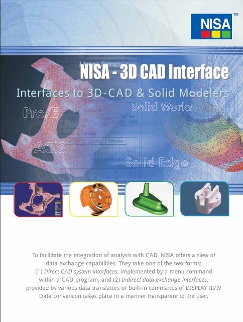
<strong>NISA</strong> - <strong>3D</strong> <strong>CAD</strong> <strong>Interface</strong><br />
<strong>Interface</strong>s to <strong>3D</strong>-<strong>CAD</strong> & Solid Modelers<br />
To facilitate the integration of analysis with <strong>CAD</strong>, <strong>NISA</strong> offers a slew of<br />
data exchange capabilities. They take one of the two forms:<br />
(1) Direct <strong>CAD</strong> system interfaces, implemented by a menu command<br />
within a <strong>CAD</strong> program, and (2) Indirect data exchange interfaces,<br />
provided by various data translators or built-in commands of DISPLAY III/IV<br />
Data conversion takes place in a manner transparent to the user.
<strong>NISA</strong> - <strong>3D</strong> <strong>CAD</strong> <strong>Interface</strong><br />
<strong>NISA</strong> - Pro/E<br />
TM<br />
Integrated Environment for the <strong>NISA</strong> family of<br />
programs<br />
<strong>NISA</strong>/Pro/E, a direct & seamless interface, provides a dynamic<br />
environment for the finite element modeling and analysis of the <strong>3D</strong><br />
TM<br />
designs created in Pro/E . Solid models are imported into EMRC's<br />
modeling systems & DISPLAY III/IV in the form of higher order NURBS<br />
surfaces and curves (along with topological data) to ensure accurate<br />
geometry transfer.<br />
DISPLAY III/IV’s powerful and robust AUTOMESHER can mesh the<br />
transferred geometry using either solid or shell elements with a single<br />
click of the mouse. The automesher generates either all hexahedron,<br />
all tetrahedron, or mixture of different types of solid elements. For<br />
surface meshing, models with all quadrilateral elements can be<br />
generated. Loads and boundary conditions can be applied directly to<br />
the geometry. Analysis can be performed from within DISPLAY III/IV<br />
or sent for batch processing of either single or multiple runs.<br />
The results of the analysis can be viewed using the advanced postprocessing<br />
features of DISPLAY III/IV.<br />
Alternatively, users can create<br />
the finite element model using<br />
Pro/MESH, apply boundary<br />
conditions & forces, and then<br />
transfer the model to DISPLAY<br />
III/IV for the analysis. The<br />
results can then be viewed<br />
using the post-processing<br />
features of DISPLAY III/IV. The<br />
program will read the FNF<br />
neutral file created by Pro/E<br />
containing the finite element<br />
data.<br />
In addition, DISPLAY III/IV<br />
offers powerful tools for<br />
manipulating the geometry to<br />
perform mapped meshing<br />
operations. MACRO language<br />
can be used to create models<br />
for parametric studies. MATH<br />
operator can be utilized to<br />
generate user defined<br />
quantities from the analysis<br />
results.<br />
<strong>NISA</strong>/ACIS<br />
TM<br />
Integrated Environment for the <strong>NISA</strong> family of<br />
programs<br />
As EMRC became a licensee of Spatial Technology's ACIS Kernel, the<br />
ACIS SAT data translator enables you to import the topological and<br />
geometric model data into DISPLAY III/IV. This is available for all<br />
ACIS-Kernel-based <strong>CAD</strong> modelers like Auto<strong>CAD</strong>/Mechanical<br />
Desktop, <strong>CAD</strong>KEY, Bentley MicroStation Modeler, and Solid<br />
Edge.<br />
<strong>NISA</strong>/ACIS, a direct & seamless interface, provides a dynamic<br />
environment for the finite element modeling and analysis of the <strong>3D</strong><br />
designs created using the ACIS geometry kernel. Solid models are<br />
imported into EMRC's modeling systems & DISPLAY III/IV in the form<br />
of higher order NURBS surfaces and curves (along with topological<br />
data) to ensure accurate geometry transfer.<br />
DISPLAY III/IV’s powerful and robust AUTOMESHER can mesh the<br />
transferred geometry using either solid or shell elements with a single<br />
click of the mouse. The<br />
automesher generates<br />
either all hexahedron, all<br />
tetrahedron, or mixture of<br />
different types of solid<br />
elements. For surface<br />
meshing, models with all<br />
quadrilateral elements can<br />
be generated. Loads and<br />
boundary conditions can be<br />
applied directly to the<br />
geometry. Analysis can be<br />
performed from within<br />
DISPLAY III/IV or sent for<br />
batch processing of either<br />
single or multiple runs. The<br />
results of the analysis can<br />
be viewed using the<br />
advanced post-processing<br />
features of DISPLAY III/IV.<br />
In addition, DISPLAY III/IV<br />
offers powerful tools for<br />
manipulating the geometry<br />
to perform mapped<br />
meshing operations.<br />
MACRO language can be<br />
used to create models for<br />
parametric studies. MATH<br />
operator can be utilized to
<strong>NISA</strong>/Solid Works<br />
TM<br />
Integrated Environment for the <strong>NISA</strong> family of<br />
programs<br />
<strong>NISA</strong>/SolidWorks, a direct seamless interface, provides a dynamic<br />
environment for the finite element modeling and analysis of the <strong>3D</strong><br />
TM<br />
designs created in SolidWorks . Solid models are imported into<br />
EMRC's modeling systems & DISPLAY III in the form of higher order<br />
NURBS surfaces and curves (along with topological data) to ensure<br />
accurate geometry transfer.<br />
DISPLAY III/IV's powerful and robust AUTOMESHER can mesh the<br />
transferred geometry using either solid or shell elements with a<br />
single click of the mouse. The automesher generates either all<br />
hexahedron, all tetrahedron, or mixture of different types of solid<br />
elements. For surface meshing, models with all quadrilateral<br />
elements can be generated. Loads and boundary conditions can<br />
be applied directly to the geometry. Analysis can be performed<br />
from within DISPLAY III/IV or sent for batch processing of either<br />
single or multiple runs. The results of the analysis can be viewed<br />
using the advanced post-processing features of DISPLAY III/IV.<br />
In addition, DISPLAY III/IV offers powerful tools for manipulating<br />
the geometry to perform mapped meshing operations. MACRO<br />
language can be used to create models for parametric studies.<br />
MATH operator can be utilized to generate user-defined quantities<br />
from the analysis results
<strong>NISA</strong> - <strong>3D</strong> <strong>CAD</strong> <strong>Interface</strong><br />
<strong>NISA</strong>/Solid Edge<br />
TM<br />
Integrated Environment for the <strong>NISA</strong> family of<br />
programs<br />
<strong>NISA</strong>/Solid Edge, a direct interface, provides a dynamic<br />
environment for the finite element modeling and analysis of the <strong>3D</strong><br />
TM<br />
designs created in Solid Edge . Solid models are imported via SAT<br />
files into EMRC's modeling systems & DISPLAY III in the form of<br />
higher order NURBS surfaces and curves (along with topological<br />
data) to ensure accurate geometry transfer.<br />
DISPLAY III's powerful and robust AUTOMESHER can mesh the<br />
transferred geometry using either solid or shell elements with a<br />
single click of the mouse. The automesher generates either all<br />
hexahedron, all tetrahedron, or mixture of different types of solid<br />
elements. For surface meshing, models with all quadrilateral<br />
elements can be generated. Loads and boundary conditions can<br />
be applied directly to the geometry. Analysis can be performed<br />
from within DISPLAY III or sent for batch processing of either single<br />
or multiple runs. The results of the analysis can be viewed using the<br />
advanced post-processing features of DISPLAY III.<br />
In addition, DISPLAY III offers powerful tools for manipulating the<br />
geometry to perform mapped meshing operations. MACRO<br />
language can be used to create models for parametric studies.<br />
MATH operator can be utilized to generate user defined quantities<br />
from the analysis results.<br />
Other <strong>Interface</strong> to Modelers<br />
IGES Data Translator<br />
To exchange geometry and finite element data created using such<br />
<strong>CAD</strong> systems as CATIA, <strong>CAD</strong>DS 5, MICRO-<strong>CAD</strong>AM, and Solid<br />
Designer, a bidirectional IGES data translator is integrated in<br />
DISPLAY III. When invoked from within DISPLAY III, it translates the<br />
required geometry data to the neutral file format for <strong>NISA</strong> finite<br />
element models. Currently supported elements are various arcs,<br />
curves, splines, lines, points, ruled surfaces, rational B-spline<br />
curves and surfaces, trimmed parametric surfaces, etc.<br />
Finite Element Model Data Translators<br />
Bi-directional data translators let you exchange finite element<br />
models between <strong>NISA</strong> II/DISPLAY III and other systems such as<br />
NASTRAN and ANSYS.<br />
Cranes Software International Limited is a leading provider of Computer Aided Engineering (CAE) services to the Automotive, Aerospace, Energy & Power, Civil, Electronics and<br />
Sporting Goods industries. Over 70 dedicated scientists, technology architects and software engineers providing <strong>NISA</strong> based solutions have helped major engineering companies<br />
reduce analysis turnaround time, improve user productivity, and ensure faster return on investments. The Company has its presence in 33 countries across the world and has a user<br />
base of more than 350,000.<br />
With a mission statement to provide its customers the best in scientific technology and to enable its customers to define new limits, Cranes is setting new standards in the scientific and<br />
engineering field. For more information, please visit www.nisasoftware.com Email: nisa@cranessoftware.com<br />
USA<br />
Cranes Software, Inc.<br />
1133 E Maple Road, Suite 103,<br />
Troy, Michigan 48083 USA<br />
P.O. Box 696, Troy, MI, 48099, USA<br />
Tel: (248) 689-0077. Fax: (248) 689-7479<br />
E-mail: sales@nisasoftware.com<br />
INDIA<br />
Cranes Software International Ltd.<br />
CAE R&D Services Division #104, Jatti Building,<br />
1st Main Road, 5th Block, Koramangala Industrial<br />
Area, Bangalore 560095, Karnataka, India.<br />
Tel: +91 (080) 40105200. Fax: +91 (080) 40105300<br />
E-mail: nisa@cranessoftware.com<br />
©2005-2008. Cranes Software International Limited. All rights reserved. All other company and product names are trademarks and/or registered trademarks of their respective owners.