Nisa Civil Brochure - CADLM
Nisa Civil Brochure - CADLM
Nisa Civil Brochure - CADLM
- No tags were found...

You also want an ePaper? Increase the reach of your titles
YUMPU automatically turns print PDFs into web optimized ePapers that Google loves.
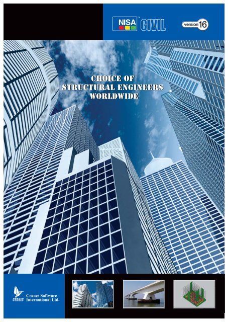
Choice ofStructural EngineersWorldwide
NISA/CIVILNISA/CIVIL is a truly integrated & versatilestructural engineering software whichoffers Structural Engineers a powerful CADbased tool for the Analysis, Design &Detailing of RCC & Steel structures likeBuildings, Bridges, Shells, Towers, IrrigationStructures & Water Retaining Structures.The software has excellent reporting andgraphing features and automaticallygenerates detailed AutoCAD® drawings.
3D FRAMESSPACE FRAMESSHELL STRUCTURESBMDCONTOURSSTRUCTURESLIBRARY2D & 3D Frames &TrussesCIVIL ENGINEER FRIENDLYIN-BUILT GRAPHICSEDITOR & DISPLAYMODE SHAPESNISA IILinear & Non Linear Static &Dynamic Finite ElementAnalysisSPILL WAYS ANALYSISRADIAL GATES ANALYSISPOST PROCESSINGBMD, Contours &Mode shapesCOMPOSITESLayered Shell,Sandwich Shell &Layered SolidBEAM DRAWINGSCOLUMN DRAWINGSFOOTING LAYOUTS
BRIDGESMACHINE FOUNDATIONSTRANSMISSION TOWERSFLOOR LOADSAUTO LOADING DUE TOFloor, Wind,Seismic, Dynamic, Moving,Temperature, Prestress,Construction Sequence,P-∆ & SnowSTEEL DESIGNas per IS, BS & AISCcodes of practiceWIND LOADSNISA/CIVILTruly Integrated &<strong>Civil</strong> Engineer FriendlySoftwareRCC DESIGNas per IS, BS & ACIcodes of practiceSEISMIC LOADSDYNAMIC LOADSCADStructural Drawingsin AutoCAD® with quanity ofSteel & Concrete takeoffREPORTSDetailed & Summary• Text• MS Word• MS ExcelMOVING LOADSPILE DRAWINGSSTAIRCASESWATER TANKS
Codes of PracticeLoading RCC SteelIndian IS 1893:2002 (Part I) IS 456:2000 (LSD) IS 800:1984IS 875:1987 (Part 2, 3 & 4) IS 456:2000 (WSD) AERB/SS/CSE-2IRC 1966 (Rev 2000)IS 3370:1967IS 13920IS 2911:1979AERB/SS/CSE-1British BS:6399 – 1997 (Part 2) BS:8110 – 1997 BS:449 – 1969BS:6399 – 1998 (Part 3) BS:5950 - 2000BS EN 1998:1 – 2004American ANSI/ASCE 7-05 ACI-318R-2005 AISC-ASDASME1-NF3000AISC-LRFD-2002AISC-ASD-2005AISC-LRFD-2005Finite Element Modeling• <strong>Civil</strong> Engineer friendly built-in graphics editor for creatingFE model of skeletal structures, shell structures and springelements• Structures primitives for 2D and 3D rigid frames andtrusses• Library of industrial structures and structures gallery formodel generation of commonly used structures• Structural shape library to generate Domes, Cones(frustums), Cylindricalshell (single, multiple)and folded plates withprovision for generatinga reticule model (modelwith beam elements)• Easy-to-use feature ofcombining two differentFLAT SLABstructural models with and without coordinate offsets• Interface to NISA/DISPLAY - Pre-Post FEA Environment• Import geometry data in DXF format from AutoCAD®• Automatic FE model generation of Bridge deck asBeam/Grillage/Shell model• Model Verification: Powerful model verification tool tocheck & rectify the presence of unconnected nodes,duplicate members and coincident nodes• Specify and view Rigid Links• Define geometry, finite element data and boundaryconditions using the powerful feature of MacrosNew in V16• Improved user interface by merging Options menu, andstructure definition & analysis menu. New open dialogand opening existing project dialog with project detailsare introduced• Graphics editor always displayed on screen• Automatic shell model generation for flat slabs• Automatic generation of shell elements from floor paneldefinition only for rectangular panels• Automaticorientation of Modelfor selected gravitydirection (Z and Y)• AutomaticFOUNDATION SPRINGcomputation ofmodulus of elasticityfor selected grade of concrete as per IS code• Tool Bar for Node/Element Editing features• Hot buttons for plotting elements, nodes and theirnumbers with element lengths are introduced• Listing of material and property IDs along withdescription for selection during Modify propertyoperationTranslator• Seamless interface to STAAD.Pro® (Geometry, Properties,Static Load Cases & Boundary Conditions)Unit SpecificationSI, MKS, FPS and User Defined units supported. User Definedoption has dual units for length and force. Desired unitsystem can be specified at the beginning or as andwhen necessary.New in V16• Default units for selectedcountry codesMODELING• Grouping of nodes and elements
LoadingFrame Loads• Transfer of floor loads such as DL, LL andPrestressing• Loads due to prestressing: stressedSnow loads from panels to supportingLoadsbefore or after placingmembers based on Two-way orOne-way distribution• Parabolic or Linear cable profile• Specify cable profile along a set ofelements which are on the same lineLOADINGDynamic Loads • Mass elements for Eigen analysis andload combinations to account forreversal of forces from subsequentresponse spectrum analysis forseismic design• Automatic generation of floor loads onsupporting members for non-rectangularshaped slab panels and sloped panels• Joint loads due to Wind and Seismiceffects (seismic coefficient or responsespectrum method with accidentalDYNAMIC LOADtorsion) as per code provision or userspecified values• Missing mass correction specification• Automatic generation of panels andincluding cut-off frequencyloads assignment for preliminary• Pre-stored spectra as per IS 1893 2002designsTemperatureNodal temperature or temperatureTruss Loads• Joint loads due to DL and LL on trussesLoadsdifference specification at joints toJoint loads due to Wind and Seismiccompute axial expansion/contractioneffects (seismic coefficient or responseand bending in local XY and XZ planes.spectrum method with accidentaltorsion) as per code provision or userspecified valuesPressure LoadsProvision to assign different pressureloads on each node of shell element.• Loads on structure are automaticallygenerated based on the followingcodes of practice:• ANSI/ASCE 7-05, IS: 1893 – 1984• IS: 875 – 1987 (Part 2, 3 and 4), BS: 6399PRESSURE LOADSPart2 1997, BS: 6399-1998 (Part3)• IS: 1893 – 2002 (Part 1)
Loading contd...Moving LoadsPowerful moving load generationalgorithm to automatically generatethe magnitude of loads transferred tomembers due to movement of eithersingle or group of vehicles alongdifferent vehicle paths on a bridgestructureMOVING LOADFollowing vehicles are included in vehicledatabase.• IRC Tracked & Wheeled Vehicles(Class AA, 70R, A & B)• Indian Railway Standards MBC-1987,MMG-1988• BS: 5400, Nominal HB Loading, RU & RLRailway Bridge Live Load• AASHTO Nominal Hs20-44 loading fordifferent vehicle lengths (8.534413.4112M)• American Railway EngineeringAssociation Cooper E-80, American AxleLoads for Two Units of Heavier DieselLocomotives• Reduction of uniformly distributed imposed floor loads inmulti-storeyed buildings for design of columns andfootings as per user specified reduction factors• Introduction of 10% (TSM), Grouping (GRP) and doublesum (DSM) methods for modal combination in dynamicanalysis• Automatic wind and seismic loads generation conformingto ASCE 7 -05• Automatic seismic load generation as per Britishstandards BS EN 1998:1-2004• Load Combination:a. Detailing as per IS: 13920 for beams and columnsb. Sway Load Combination as per ACI & AERB concretecodesc. Option to ignore slenderness for column designagainst P-∆ load• Automatic computation of seismic forces as per numberof floors above the specified base• Computation of static accidental torsion as per codes ofpractice with/withoutnegative shears• All or selected loadsspecified at any floorlevel can be copied toother floors• Listing of load sets in aselected load caseGENERAL SECTIONwith option to select load sets to view them in graphicdisplay• Extract predefined load combinations from a fileNew in V16BOWSTRING• Auto Load generation for dead loads, live loads, seismicloads, wind loads and their corresponding loadcombinationsLoad case dependent Member End ReleaseDifferent end release conditions for an element can bespecified in conjunction with loads, as analysis with differentload cases can be performed in one session.Load case dependent Inactive Member SpecificationUseful for construction sequence analysis for a particularloading condition. Members specified as ‘Inactive’ willnot be included while formulating stiffness matrix andload vector.
Finite Element AnalysisNISA/CIVIL comes bundled with DISPLAY & NISA II SOLVER.DISPLAY: State-of-the-art Pre & Post processing environmentwhich can be used for tasks such as complex 3D SolidElement modeling and analysis.NISA II SOLVER: Offers an impressive list of linear & nonlinear -static & dynamic analysis features complemented with anextensive finite element library. It has efficient solvers likedirect (frontal and sparse) and iterative solvers.• Static Analysis (Linear, Non-linear & Contact)• Eigenvalue Analysis• Modal Dynamic Analysis(Transient, FrequencyResponse, RandomVibration, ShockSpectrum & Direct Transient)• Heat Transfer Analysis(Optional)• Non-linear Analysis(Material, Geometric orboth)• Composite Analysis (Static,Dynamic & Heat Transfer)MODE SHAPE• Design results viewer for individual or failed elements• Force factors such as Pu/fckBD and Mu/fckBD 2 used inconcrete design can be plotted as done for BMD/SFD etc.• Bending Moments, Force Factors etc can be output as atable in a report file• Displacements and Reactions can be displayed at thenodal locations for documentation• Viewing of Mass, Pipe and 3D Solid elements aresupported including realistic plotNew in V16• Hot buttons for plotting BMD features• Additional BMD features:a. Color Band numbersb. Contours without element boundary• Dynamic rotation in Graphic viewer• Mouse wheel support for graphic features such aszoom & pan• Exporting to Excel: FE model data such as Node IDs andtheir co-ordinates, Element IDs and their nodalconnectivity along with sectional sizes, results of analysissuch as reactions & member forces• Fluid Analysis (Seepage Analysis & Shadow effect ofbuildings) (Optional)• P - ∆ AnalysisPost Processing• Display of loading diagram for different load cases• Display of bendingmoment, shear forceand deflectiondiagrams along withlisting at twentydifferent sections• BMD/SFD can beviewed with colorband contours• Animation of deflected shape, eigen modes & stresscontoursANALYSISDesign ModesANALYSIS REPORTStructural designs can be performed as per three modes ofdesign:• Integrated Online• Integrated Offline• InteractiveIntegrated offline mode is a special and <strong>Civil</strong> Engineerfriendly option to carry out alternative designs withoutrepetitive analysis.
Structural DesignRC SlabRC BeamsRC ColumnsRC FootingsStructural design of RC slab panels withdifferent support conditions. Short andlong term deflection in slab panels.Interactive design of sector, circular,triangular, skew, waffle slabs and sphericaldomes based on theory of plates andshellsStructural design of RC beams subjected toFlexure, Shear and TorsionStructural design of RC columns subjectedto Axial loads with Uniaxial and Biaxialbending based on Interaction orEquilibrium approachStructural design of isolated footings ofconstant and varying thickness with orwithout pedestals, combined footings, solidslab, beam and slabRC Corbel Design of RC Corbel as per American,British and Indian codes of practicePipeDesign of Straight and Elbow type pipes asper ASME-NB, NC & ND codes of practiceLiquidDesign of ‘Overhead and ground levelRetaining water tanks’ as per IS: 3370,Structures parts I, II & IVStructural Steel Code checking of Standard (Channel, I,Elements Angle, T, Pipes and RHS/SHS) or userdefined sections subjected to axial,bending and torsional effects along withrecommendations in case of inadequacies.Design of different types of built-upsections and Plate girdersGANTRYFOOTINGRaftDesign of raft as per Rigid Beam Theoryconforming to Indian standardsRC Plate/Shell Structural design of plate/shell elements atnodal and centroidal points due to axial,flexural and shear stressesShear Wall Design of Shear wall as per IndianstandardsFlat Slab Flat Slabs can be modeled, analyzed byEquivalent Frame Method and ShellElement Method and designed as perIndian, British & American standardsRC Staircase Straight, Dog-legged, Open newel withwaist slab/Tread & Riser, Helicoidal andscissor type staircase as per Indian, British& American standardsRC Retaining T or L shaped with or without keys andWallbatter towards heel or toePile Foundation Design of Bored Cast-in-situ, Friction, EndBearing, Under Reamed and Precast DrivenPile Foundation (Piles and pile caps)as per IS – 2911New in V16• Implementation of concrete designs conforming toAERB/SS/CSE-1: Atomic Energy Regulatory Board of India• Implementation of steel designs conforming toAERB/SS/CSE-2: Atomic Energy Regulatory Board of India• Automatic Selection of sectional sizes for beams &columns based on user specified % of steel and from a listof preferred sectional sizes• Automatic selection of isolated footing sizes from the userspecified list. Additional features for isolated footing suchas support height specification, overburden pressure anddesign of eccentric isolated footings• IS: 13920 Seismic ductile detailing design provisions forthe design of beams and columns• Steel Design as per AISC-2005
CAD DrawingsIn NISA/CIVIL post-processing is not limited to analysis resultsonly. At the click of a button, design results are processed toproduce design drawings of good quality in an AutoCAD®environment. Separate drawings are made for differentstructural elements even though all of them are designed inthe same session. Drawing entities are present in differentlayers and colors for easy identification and editing. They canbe customized as per requirements.Piles andPile CapsTypical sections at top and front viewsindicating reinforcement details along withcomplete pile layoutRC SlabRC BeamsRC ColumnsRC FootingsShellsFlat SlabsRC StairsRC RetainingWallsSectional top view indicating top andbottom reinforcement at different floorlevels. Typical cross section showingcurtailment or bending of bars near theedge and intermediate beamsLongitudinal section and cross sections atsupport and span regions indicating rebararrangement and stirrup details along withframing planCross section along with reinforcementdetails in tabular form. Columns havingsimilar reinforcement arrangement aregrouped togetherSectional top and front views indicatingreinforcement details for isolated andcombined footing of solid slab type andcross sections in beam and slab footingReinforcement requirement is displayed inthe form of color contoursDrawing generation of Flat SlabsPlan, Flight sectional view, Cross sectionsshowing reinforcement details,Bar bending schedule and Steel quantitytableLongitudinaland crosssectional viewsindicatingreinforcementdetails in stem,base and keysif anyRETAINING WALLPILE DRAWINGOverhead and Plan, sectional elevation, cross-sections forGround Level beams and columnsWater TanksSteel Structural Front view along with section designation,Elements sectional details and profile of the sectionof individual elements in a tabular formNew in V16• Rebar Rationalization for beams & columns• Drawing Layout editor to specify member offsets.• Automatic drawing generation for beams of unequaldepths• Reinforcement & Layout drawing generation for differenttypes of common shapes such as T,L,I,H & hollow & solidrectangular, circular, hexagon and octagon• Drawing generation for Counter Fort retaining wall• Drawing generation for Corbels• Feature to add Notes in Detailer & Drawings for Steel andRetaining wall• Slab drawing is incorporated in interactive designmode alsoReportsDesign results are reported as summary and detailedoutputs. Design reports can also be generated in Text,MS Word and MS Excel format.DESIGN REPORT
USACranes Software, Inc.1133 E Maple Road, Suite 103, Troy, Michigan 48083 USAP.O. Box 696, Troy, MI, 48099, USATel : (248) 689-0077Fax : (248) 689-7479E-mail : sales@nisasoftware.comINDIACranes Software International Ltd.Cranes Engineering,#104, Jatti Building, 1st Main Road,5th Block, Koramangala Industrial Area,Bangalore 560095, Karnataka, India.Tel : +91 (080) 40105200Fax : +91 (080) 40105300E-mail : nisa@cranessoftware.comwww.cranessoftware.com | www.nisasoftware.com© 2005-2008 Cranes Software, Inc. All Rights Reserved.NISA, NISA/CIVIL & NISA DesignStudio are trademarks of Cranes Software, Inc. All other product/brand names are the trademarks or registered trademarks of their respective owners.AutoCAD ® is a registered trademark of Autodesk, Inc. STAAD.Pro® is a registered trademark of Bentley Systems, Inc.