Flinger Disk I - Dean Industrial
Flinger Disk I - Dean Industrial
Flinger Disk I - Dean Industrial

Create successful ePaper yourself
Turn your PDF publications into a flip-book with our unique Google optimized e-Paper software.
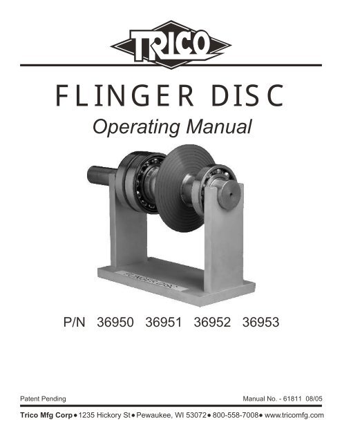
FLINGER DISC<br />
Operating Manual<br />
P/N 36950 36951 36952 36953<br />
Patent Pending Manual No. - 61811 08/05<br />
Trico Mfg Corp 1235 Hickory St Pewaukee, WI 53072 800-558-7008 www.tricomfg.com
Table of Contents<br />
Introduction . . . . . . . . . . . . . . . . . . . . . . . . 3<br />
Customer Satisfaction/Warranty . . . . . . . . . . . . . . . . . . 3<br />
Important Safeguards . . . . . . . . . . . . . . . . . . . . . 4<br />
<strong>Flinger</strong> Disc Specifications . . . . . . . . . . . . . . . . . . . . 4<br />
Installation . . . . . . . . . . . . . . . . . . . . . . . . 5 - 6<br />
Unit Operation . . . . . . . . . . . . . . . . . . . . . . . 7<br />
Replacement Parts . . . . . . . . . . . . . . . . . . . . . . 7<br />
Page 2
Introduction<br />
Thank you for purchasing the Trico Mfg. Corp. <strong>Flinger</strong> Disc. The <strong>Flinger</strong> Disc is an alternative to<br />
“Slinger”/Oil ring lubrication typically found in API centrifugal pumps power frames. The purpose of<br />
either a <strong>Flinger</strong> Disc or Oil Ring is to lubricate and cool the bearings and prevent stratification of the<br />
oil (hot/cold). Other Lubricating Discs products have been made from non-flexible metallic material<br />
that is limited to the same diameter of the bearing housing. Trico's <strong>Flinger</strong> Disc is made of Viton®<br />
allowing flexibility during installation while maintaining similar submersion into the oil bath as the<br />
traditional oil ring. The <strong>Flinger</strong> Disc should submerse in the oil bath the same amount as the current<br />
Oil Ring which is typically .250 to .50 inches. The <strong>Flinger</strong> Disc has a stainless steel hub to maintain<br />
concentricity and is positively secured to the shaft with set screws. For maximum versatility and<br />
minimum stocking requirements, Trico offers two <strong>Flinger</strong> Discs that cover a variety of bore diameter<br />
size ranges that can be machined by the customer or Trico to meet the application needs.<br />
Mounting hub bore diameter size ranges offered: 1.5" to 2.5" 2.5" to 4". Raised rings are molded<br />
on .25 inch intervals to adapt to various application requirements. The end user trims the disc to the<br />
required diameter to achieve the proper level of submersion into the oil.<br />
Please read this manual carefully to learn how to correctly modify and install the <strong>Flinger</strong> Disc.<br />
Reading this manual will help you and others avoid personal injury, damage to the product and<br />
equipment it is installed on. After reading the manual it should be kept in a safe place for future<br />
reference.<br />
Customer Satisfaction<br />
Trico Mfg. Corp. is proud of it's commitment to quality. This product is guaranteed against defects in<br />
workmanship and materials for one year from date of purchase. Under this guarantee, Trico will<br />
replace or repair product that is determined to be defective. Normal wear and tear, misuse or<br />
improper installation is not covered under this warranty. This warranty is limited to the repair or<br />
replacement of defective parts only. Trico is not responsible for incidental or consequential damage.<br />
To reach Customer Service call 800-558-7008 (USA only) or 262-691-9336. Customer Service is<br />
available Monday through Friday 7:30 am 5:00 pm, central time. Customer Service can also be<br />
reached by fax, 262-691-2576, or write to:<br />
Customer Service<br />
Trico Mfg. Corp.<br />
1235 Hickory Street<br />
Pewaukee, WI 53072<br />
custserv@tricomfg.com<br />
www.tricomfg.com<br />
Page 3
Important Safeguards<br />
1. Read Instructions Thoroughly<br />
If you are unsure on the instructions contact Trico Customer Service.<br />
2. Retain Instructions<br />
Safety and operating instructions should be retained for future reference.<br />
3. Heed Warnings<br />
All warnings on this product and in these instructions should be adhered to.<br />
4. Follow Instructions<br />
All installation, mounting, and operating instructions should be followed.<br />
Customer Satisfaction<br />
<br />
<br />
<br />
<br />
36950 <strong>Flinger</strong> disc 1.5 - 2.5” ID, 3.5 - 7" OD<br />
Customer Machines bore to proper diameter<br />
36951 <strong>Flinger</strong> disc-customer specified ID, 3.5 - 7" OD<br />
Customer supplies bore diameter to Trico for machining<br />
36952 <strong>Flinger</strong> disc 2.5" ID, 5 - 9.5" OD<br />
Customer Machines bore to proper diameter<br />
36953 <strong>Flinger</strong> disc-customer specified ID, 5 - 9.5" OD<br />
Customer supplies bore diameter to Trico for machining<br />
MAXIMUM OPERATING TEMP<br />
HUB MATERIAL<br />
FLINGER MATERIAL<br />
SHAFT CONNECTION<br />
OUTSIDE DIAMETER<br />
INSIDE DIAMETER<br />
36950, 36951 36952, 36953<br />
350ºF 350ºF<br />
304 Stainless Steel 304 Stainless Steel<br />
Viton®<br />
Viton®<br />
(2) 10-32 Set Screws (2) 10-32 Set Screws<br />
3.5 - 7.0 inches 5.0 - 9.5 inches<br />
1.5 - 2.5 inches 2.5 - 4.0 inches<br />
Caution: Maximum Operating Speed = 3,600 rpm.<br />
36950, 36951<br />
36950, 36951<br />
Page 4
Installation<br />
Caution: Prior to installing the <strong>Flinger</strong> Disc, insure Viton® is compatible with oil.<br />
In order to properly install the <strong>Flinger</strong> disc four pieces of data need to be determined:<br />
Number of <strong>Flinger</strong> Discs required<br />
Mounting location on the shaft<br />
Shaft diameter where disc is being installed<br />
Outside diameter of disc<br />
Number of Discs Required:<br />
The number of discs required is dependent on the number of Oil Rings currently installed on the<br />
shaft. If the specific shaft has two Oil Rings then two <strong>Flinger</strong> Discs are required. If there is only one<br />
Oil Ring then one <strong>Flinger</strong> Disc is sufficient.<br />
Mounting Location on the Shaft:<br />
The <strong>Flinger</strong> Disc should be mounted in close proximity to existing Oil Ring. If a groove exists in the<br />
shaft, mount Disc next to either side of the groove depending on shaft configuration.<br />
Shaft Diameter where disc is being installed:<br />
The required <strong>Flinger</strong> Disc bore dimension will be determined based on the shaft diameter at the<br />
desired mounting location. Once the mounting location is determined, the shaft diameter should be<br />
verified using a micrometer. The <strong>Flinger</strong> Disc bore should be machined to allow for a slip fit during<br />
installation.<br />
Recommendation: <strong>Flinger</strong> Disc Bore = Shaft Diameter (D) + .005”<br />
Outside Diameter of Disc:<br />
The <strong>Flinger</strong> Disc should submerse into the oil the same amount as existing Oil Rings which is<br />
typically between .25” and .5”. The required outside diameter can be calculated using three different<br />
formulas based on dimensions obtained from the Pump OEM or dimensional data obtained by using<br />
a micrometer to measure the shaft and a new Oil Ring. The different formulas for known dimensions<br />
are as follows. (Refer to Figure 1 and 2)<br />
Outside Diameter = [(F) + (A)] x 2<br />
Outside Diameter = [(B - E) + (E/2) + (C - B)/2] x 2<br />
Outside Diameter = [(B - D) + (D/2) + (C - B)/2] x 2<br />
Submersion Level Known<br />
Groove exists in Shaft for Ring<br />
No Groove in Shaft<br />
DIM DESCRIPTION INCHES<br />
D<br />
A<br />
B<br />
C<br />
Ring Submerged in Oil<br />
Ring Diameter (Inner)<br />
Ring Diameter (Outer)<br />
A<br />
B C<br />
E<br />
OIL LEVEL<br />
F<br />
D<br />
E<br />
Shaft Diameter<br />
Diameter of Ring Groove<br />
Fig 1<br />
F<br />
Shaft CL to Oil Level<br />
Page 5
FLINGER DISC RADIUS = (B-E) + (.5E) + [(C-B)/2]<br />
OIL<br />
RING<br />
SHAFT<br />
FLINGER<br />
DISC RADIUS<br />
Fig 2<br />
Consult Pump OEM for these dimensions if not accurately available<br />
Caution: Incorrect <strong>Flinger</strong> Disc outside diameter may cause:<br />
1. Insufficient lubrication if diameter is too small to dip into oil<br />
2. High operating temperatures if diameter is too large causing excessive churning<br />
of the oil.<br />
Caution: Only a new Oil Ring should be used to obtain dimensional data. A used Oil<br />
Ring may have worn resulting in incorrect dimensional data.<br />
Caution: After calculating proper outer diameter of <strong>Flinger</strong> Disc, measure existing<br />
housing bore in area where disc would rotate. Ensure proper clearance exists to avoid<br />
any contact of <strong>Flinger</strong> Disc with the housing.<br />
Trimming Disc:<br />
After determining the proper diameter for the <strong>Flinger</strong> Disc, the disc can be cut to using industrial<br />
grade scissors, utility knife, or gasket cutters. The cutting should occur in a continuous process to<br />
avoid sharp edges. Use the ridges as guidelines for cutting to ensure a symmetric disc.<br />
The disc should be cut on either the inside or outside of the ridge. After the Disc is cut to the correct<br />
diameter use a fine grit (400) sandpaper to clean up any loose edges. Prior to installing disc on shaft,<br />
it should be cleaned with a mild cleaner (compatible with Viton) to remove any particles.<br />
Installing Disc:<br />
After machining the bore of the disc and trimming the outer diameter to the correct dimensions, the<br />
disc can be installed on the shaft. Ensure shaft is free of any burrs prior to installing the disc. Locate<br />
disc on shaft in close proximity to previous Oil Ring location. Once in position, torque the two10-32<br />
set screws provided to 36 in-lbs (not lubricated) or 22 in-lbs (lubricated). Application of a thread<br />
locking product such as Loctite 222 is recommended to be applied.<br />
Page 6
Unit Operation<br />
The <strong>Flinger</strong> Disc provides splash type oil mist lubrication to the bearings. The proper amount of oil<br />
per the OEM recommendations should be added to the housing and verified by a bullseye sight<br />
gauge if applicable. The <strong>Flinger</strong> Disc will provide the proper lubrication as long as the correct outside<br />
diameter was calculated based on either the:<br />
<br />
<br />
OEM dimensions - Shaft Centerline to Oil level and Existing Oil Ring Submersion,<br />
Formulas above relating to shaft diameter, Oil Ring outer and inner diameter and Oil ring<br />
submersion.<br />
Monitoring the bearing operating temperatures with a temperature gun after starting the pump is<br />
recommended. If the temperatures are higher than standard operating temperatures recommended<br />
by the OEM, the bearing housing should be inspected to ensure the <strong>Flinger</strong> Disc is properly<br />
submersed into the oil.<br />
Replacement Parts<br />
<br />
<br />
<br />
<br />
36950 <strong>Flinger</strong> disc 1.5 2.5" ID, 3.5 - 7" OD<br />
36951 <strong>Flinger</strong> disc-customer specified ID, 3.5 - 7" OD<br />
36952 <strong>Flinger</strong> disc 2.5 - 4" ID, 5 - 9.5" OD<br />
36953 <strong>Flinger</strong> disc-customer specified ID, 5 - 9.5" OD<br />
Page 7
Trico Mfg Corp 1235 Hickory St Pewaukee, WI 53072 800-558-7008 www.tricomfg.com