Omron B3W-4050 datasheet - Octopart
Omron B3W-4050 datasheet - Octopart
Omron B3W-4050 datasheet - Octopart

Create successful ePaper yourself
Turn your PDF publications into a flip-book with our unique Google optimized e-Paper software.
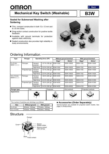
Mechanical Key Switch (Washable)<br />
<strong>B3W</strong><br />
Sealed for Submersed Washing after<br />
Soldering<br />
Thin, compact construction in both 12 x 12 mm and<br />
6 x 6 mm sizes.<br />
Snap-action contact construction for positive tactile<br />
feedback.<br />
Available with ground terminals for protection<br />
against static electricity.<br />
Sealed construction also provides high reliability in<br />
dusty environments.<br />
Ordering Information<br />
Type Plunger Operating force (OF) Without ground terminal With ground terminal<br />
Bags* Sticks* Bags* Sticks*<br />
6 x 6 mm Flat type General 1.57 N (160 gf) <strong>B3W</strong>-1000 <strong>B3W</strong>-1000S <strong>B3W</strong>-1100 <strong>B3W</strong>-1100S<br />
<strong>B3W</strong>-1<br />
purpose<br />
High-force 2.25 N (230 gf) <strong>B3W</strong>-1002 <strong>B3W</strong>-1002S <strong>B3W</strong>-1102 <strong>B3W</strong>-1102S<br />
Projected type General 1.57 N (160 gf) <strong>B3W</strong>-1050 <strong>B3W</strong>-1050S <strong>B3W</strong>-1150 <strong>B3W</strong>-1150S<br />
purpose<br />
High-force 2.25 N (230 gf) <strong>B3W</strong>-1052 <strong>B3W</strong>-1052S <strong>B3W</strong>-1152 <strong>B3W</strong>-1152S<br />
12 x 12 mm<br />
<strong>B3W</strong>-4<br />
Flat type<br />
Projected type<br />
General 1.96 N (200 gf) <strong>B3W</strong>-4000 <strong>B3W</strong>-4000S <strong>B3W</strong>-4100 <strong>B3W</strong>-4100S<br />
purpose<br />
High-force 3.43 N (350 gf) <strong>B3W</strong>-4005 <strong>B3W</strong>-4005S <strong>B3W</strong>-4105 <strong>B3W</strong>-4105S<br />
General 1.96 N (200 gf) <strong>B3W</strong>-<strong>4050</strong> <strong>B3W</strong>-<strong>4050</strong>S <strong>B3W</strong>-4150 <strong>B3W</strong>-4150S<br />
purpose<br />
High-force 3.43 N (350 gf) <strong>B3W</strong>-4055 <strong>B3W</strong>-4055S <strong>B3W</strong>-4155 <strong>B3W</strong>-4155S<br />
Plunger type Flat Projected Flat (vertical) Projected (vertical)<br />
Appearance<br />
* The number of switches per stick/bag is as follows:<br />
Size Without ground With ground<br />
6 x 6 mm 80/stick, 100/bag 75/stick, 100/bag<br />
12 x 12 mm 45/stick, 100/bag 40/stick, 100/bag<br />
Structure<br />
Plunger<br />
Accessories (Order Separately)<br />
Special keytops are available for projected switch models. See<br />
page 27 (Product B32).<br />
Cover<br />
Spacer<br />
Sealed rubber<br />
Moving contact<br />
(disk spring)<br />
Base<br />
Fixed contact
Specifications<br />
Ratings<br />
Switching capacity<br />
Insulation voltage<br />
5 to 24 VDC, 1 to 50 mA (resistive load)<br />
30 VDC<br />
Characteristics<br />
Contact configuration<br />
Contact resistance<br />
Insulation resistance<br />
Dielectric strength<br />
Bounce time<br />
Vibration resistance<br />
Shock resistance<br />
Life expectancy<br />
Ambient temperature<br />
SPST-NO<br />
100 mΩ max. (Rated 5 VDC, 1 mA)<br />
100 MΩ min. (at 250 VDC)<br />
500 VAC, 50/60 Hz for 1 min<br />
5 ms max.<br />
Ambient humidity 35% to 85%<br />
Weight<br />
Operating Characteristics<br />
Malfunction: 10 to 55 Hz, 1.5 mm double amplitude<br />
Destruction: 1,000 m/s 2 min. (Approx. 100 G min.)<br />
Malfunction: 100 m/s 2 min. (Approx. 10 G min.)<br />
<strong>B3W</strong>-1000:<br />
General purpose:1,000,000 operations min.<br />
High-force: 300,000 operations min.<br />
<strong>B3W</strong>-4000:<br />
General purpose:3,000,000 operations min.<br />
High-force: 1,000,000 operations min.<br />
-25°C to 70°C (with no icing)<br />
6 x 6 mm: approx. 0.3 g, 12 x 12: approx. 1.00 g<br />
Item <strong>B3W</strong>-1000 <strong>B3W</strong>-4000<br />
General purpose High-force General purpose High-force<br />
Operating force (OF) 1.57 N (160 gf max.) 2.25 N (230 gf max.) 1.96 N (200 gf max.) 3.43 N (350 gf max.)<br />
Reset force (RF min.) 0.2 N (20 gf max.) 0.49 N (50 gf) 0.29 N (30 gf) 0.49 N (50 gf)<br />
Pretravel (PT) 0.25 +0.2 / –0.1 mm 0.3 +0.2 / –0.1 mm<br />
Engineering Data<br />
Operating Force vs. Stroke (Typical)<br />
<strong>B3W</strong>-1<br />
<strong>B3W</strong>-4<br />
Operating force (gf)<br />
High-force<br />
Operating force (gf)<br />
High-force<br />
General purpose<br />
General purpose<br />
Stroke S (mm)<br />
Stroke S (mm)
Dimensions<br />
Note:<br />
1. Unless otherwise specified, a tolerance of ± 0.4mm applies to all dimensions.<br />
2. No terminal numbers appear on the switches. To orient a switch in the “bottom view” position, turn it so that the terminals are on the<br />
up and down sides and the word OMRON is right-side up.<br />
6 x 6 mm Models<br />
Flat Plunger Type<br />
(without Ground Terminal)<br />
<strong>B3W</strong>-1000, -1002<br />
6.6<br />
6<br />
3.3 dia.<br />
4.5<br />
(Bottom view)<br />
PCB Mounting<br />
(Top View)<br />
Terminal Arrangement<br />
/Internal Connections<br />
(Top View)<br />
4.3<br />
3.4<br />
4.5±0.1<br />
3.5<br />
6.5<br />
7.7<br />
(1.8)<br />
0.3<br />
0.7 0.7<br />
6.5±0.1<br />
Four 1±0.05 dia.<br />
Flat Plunger Type<br />
(with Ground Terminal)<br />
<strong>B3W</strong>-1100, -1102<br />
6.6<br />
6<br />
3.3 dia.<br />
4.5<br />
PCB Mounting<br />
(Top View)<br />
Terminal Arrangement<br />
/Internal Connections<br />
(Top View)<br />
1.5<br />
4.3<br />
3.4<br />
4.5±0.1<br />
3.5<br />
4.1±0.1<br />
6.5<br />
7.7<br />
0.3<br />
0.7 0.7<br />
6.5±0.1<br />
Five 1±0.05 dia.<br />
Projected Plunger Type<br />
(without Ground Terminal)<br />
<strong>B3W</strong>-1050, -1052<br />
6.6<br />
6<br />
3.3 dia.<br />
4.5<br />
PCB Mounting<br />
(Top View)<br />
Terminal Arrangement<br />
/Internal Connections<br />
(Top View)<br />
1.8<br />
2.4<br />
7.3<br />
4.3<br />
3.4<br />
4.5±0.1<br />
3.5<br />
0.3<br />
6.5<br />
7.7<br />
(1.8)<br />
0.7 0.7<br />
6.5±0.1<br />
Four 1±0.05 dia.<br />
Projected Plunger Type<br />
(with Ground Terminal)<br />
<strong>B3W</strong>-1150, -1152<br />
6.6<br />
6<br />
3.3 dia.<br />
4.5<br />
PCB Mounting<br />
(Top View)<br />
Terminal Arrangement<br />
/Internal Connections<br />
(Top View)<br />
1.8<br />
2.4<br />
7.3<br />
4.3<br />
3.4<br />
4.1±0.1<br />
4.5±0.1<br />
3.5<br />
(1.8)<br />
0.3<br />
1.5<br />
6.5<br />
0.7 0.7<br />
7.7<br />
6.5±0.1<br />
Five 1±0.05 dia.
12 x 12 mm Models<br />
Flat Plunger Type<br />
(without Ground Terminal)<br />
<strong>B3W</strong>-4000, -4005<br />
12<br />
12<br />
7.1 dia.<br />
5<br />
PCB Mounting<br />
(Top View)<br />
Terminal Arrangement<br />
/Internal Connections<br />
(Top View)<br />
Two 1.8±0.05 dia.<br />
3.5<br />
4.3<br />
0.3<br />
12.5<br />
13.8<br />
3.55<br />
(1.8)<br />
1 1<br />
9<br />
12.5±0.1<br />
5±0.1 9±0.1<br />
Four 1.2±0.05<br />
Flat Plunger Type<br />
(with Ground Terminal)<br />
<strong>B3W</strong>-4100, -4105<br />
12<br />
12<br />
7.1 dia.<br />
5<br />
PCB Mounting<br />
(Top View)<br />
Two 1.8±0.05 dia.<br />
Terminal Arrangement<br />
/Internal Connections<br />
(Top View)<br />
1.6<br />
5±0.1 9±0.1<br />
3.5<br />
4.3<br />
0.3<br />
12.5<br />
13.8<br />
3.55<br />
(1.8)<br />
1 1<br />
9<br />
6.9±0.1<br />
12.5±0.1<br />
Five 1.2±0.05 dia.<br />
Projected Plunger Type<br />
(without Ground Terminal)<br />
<strong>B3W</strong>-<strong>4050</strong>, -4055<br />
12<br />
12<br />
5<br />
PCB Mounting<br />
(Top View)<br />
Terminal Arrangement<br />
/Internal Connections<br />
(Top View)<br />
Two 1.8±0.05 dia.<br />
1.8<br />
3.8<br />
5±0.1 9±0.1<br />
7.3<br />
3.5<br />
4.3<br />
3.55<br />
12.5±0.1<br />
Four 1.2±0.05<br />
Projected Plunger Type<br />
(with Ground Terminal)<br />
<strong>B3W</strong>-4150, -4155<br />
12<br />
12.5<br />
13.8<br />
12<br />
0.3<br />
(1.8)<br />
5<br />
1 1<br />
9<br />
PCB Mounting<br />
(Top View)<br />
Terminal Arrangement<br />
/Internal Connections<br />
(Top View)<br />
Two 1.8±0.05 dia.<br />
1.8<br />
5±0.1 9±0.1<br />
7.3<br />
4.3 3.55<br />
6.9±0.1<br />
3.5<br />
1.6<br />
12.5<br />
13.8<br />
(1.8)<br />
0.3<br />
1 1<br />
9<br />
12.5±0.1<br />
Five 1.2±0.05 dia.
Precautions<br />
• Do not apply additional force to the plunger once it has stopped<br />
moving.<br />
• Do not allow flux or flux foam to penetrate onto the component<br />
side of the PCB.<br />
• Use a single-sided PCB with a thickness of 1.6 mm. The<br />
switches may be damaged due to instability or heat from<br />
soldering if other PCBs (other thickness or through holes) are<br />
used. If is it necessary to use another PCB, test the compatibility<br />
and processing in advance.<br />
• Do not repeatedly press the plunger off-centre or from an acute<br />
angle.<br />
• <strong>B3W</strong> Switches are designed to allow submersed washing after<br />
soldering. When washing, please follow the guidelines given as<br />
follows:<br />
1. Clean with alcohol solvents. Do not use chlorine solvents or<br />
water.<br />
2. When using ultrasonic cleaning in 2- or 3-tank systems, do not<br />
clean for more than 1 minute at a time or for more than 3 minutes<br />
total.<br />
3. Do not apply external force to the switch during washing.<br />
4. Do not wash immediately after soldering. Allow components to<br />
stand for at least 3 minutes before washing if possible.<br />
5. Solder at 260±5C and within 2 tries.<br />
6. The switch cannot be used where subject to direct contact with<br />
water.