to down load Installation specification for ipso HW131 - Laundry ...
to down load Installation specification for ipso HW131 - Laundry ...
to down load Installation specification for ipso HW131 - Laundry ...

Create successful ePaper yourself
Turn your PDF publications into a flip-book with our unique Google optimized e-Paper software.
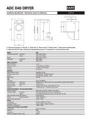
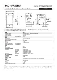
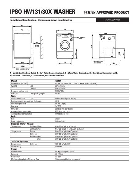
IPSO <strong>HW131</strong>/30X WASHER<br />
<strong>Installation</strong> Specification - Dimensions shown in millimetres<br />
APPROVED PRODUCT<br />
I/<strong>HW131</strong>/30X/09/04<br />
A - Ventilation Overflow Outlet, B - Soft Water Connection (cold), C - Warm Water Connection, D - Hard Water Connection (cold),<br />
E - Electrical Connection, F - Drain Outlet, G - Steam Connection<br />
Model<br />
<strong>HW131</strong><br />
Dimensions (HxWxD) 1170 x 780 x 905mm 1310 x 950 x 940mm (Boxed)<br />
Weight Nett 287kg (632lb)<br />
Loaded<br />
340kg (750lb)<br />
Dynamic bot<strong>to</strong>m <strong>load</strong><br />
1000N/16Hz<br />
G-Force Low spin/High spin 88/363<br />
Water<br />
No. of inlet valves Coin 1 hot & 2 cold (hard & soft)<br />
Recommended temperature (Hot water) 60ºC<br />
Minimum pressure<br />
1.6 bar (25psi)<br />
Inlet size<br />
3<br />
/4” BSP<br />
Flow rate<br />
22 litres/min per supply<br />
Average hot consumption<br />
47.5 litres per cycle<br />
Average <strong>to</strong>tal consumption<br />
190 litres per cycle<br />
Drain<br />
Size<br />
50mm<br />
Drain by gravity<br />
80 litres/min<br />
Electrical <strong>HW131</strong> Manual<br />
Three phase Self-heat 12Kw 415v/50Hz/3ph + N/32A/ph<br />
Self-heat 9Kw<br />
415v/50Hz/3ph + N/32A/ph (Optional)<br />
Single phase Steam 240v/50Hz/1ph/16A (Optional)<br />
Boiler fed<br />
240v/50Hz/1ph/16A (Optional)<br />
Self-heat 6Kw<br />
240v/50Hz/1ph/32A (Optional)<br />
9Kw<br />
240v/50Hz/1ph/45A (Optional)<br />
30X Coin Operated<br />
Single phase Boiler fed 240v/50Hz/1ph/16A<br />
Mo<strong>to</strong>r rating<br />
1500watt<br />
Steam<br />
Consumption<br />
13.2Kg/cycle (29lb/cycle)<br />
Pressure<br />
90 - 110psi<br />
Connection<br />
3<br />
/8” BSP<br />
Minimum <strong>Installation</strong> Distance- Rear<br />
600mm - read fixings on reverse
Foundations<br />
The machine requires a foundation of solid and level concrete construction<br />
at least 200mm deep. If a new concrete pad is <strong>to</strong> be laid it must be keyed<br />
correctly in<strong>to</strong> the existing foundations. The concrete foundation should<br />
always be greater in size than the machine and a minimum of 100mm from<br />
the edge of the concrete foundation <strong>to</strong> the edge of the machine must be<br />
provided. It is recommended that a metal raising plinth is used in<br />
conjunction with the concrete foundation. This will make the installation<br />
considerably easier, simplify <strong>for</strong> future servicing and raise the machine<br />
above the drain level <strong>for</strong> a correct evacuation of water from the machine. If<br />
block and beam or any type of floor with a void underneath is present,<br />
seek advice.<br />
Fixings<br />
A minimum service distance of 600mm is <strong>to</strong> be provided behind the<br />
machine (400mm if metal raising plinth is <strong>to</strong> be used). The machine needs<br />
<strong>to</strong> be securely fixed <strong>to</strong> the floor by 4 x M12 x 100mm fixing bolts. The type<br />
and <strong>specification</strong> of bolts will be determined by the quality and type of<br />
floor construction. The following types are generally accepted: rawlbolt,<br />
resin bonded fixings (chemfix) and Thru’ bolts.<br />
Drainage<br />
The machine is fitted with a gravity drain outlet and must be positioned<br />
higher than the main drain. The drain outlet must be fitted with a “trap”<br />
removable <strong>for</strong> cleaning purposes. This is <strong>to</strong> ensure against odour recirculation.<br />
To meet Health and Safety guidelines the drain must be sealed<br />
inside the building. Where a foul water supply discharges <strong>to</strong> an outside<br />
fouldrain or gully, there is no requirement <strong>to</strong> seal the system, as it must be<br />
ventillated and accessible <strong>for</strong> cleaning. The underlying trap will prevent foul<br />
air from rising from the sewer. External gullies may be so placed <strong>for</strong> the<br />
displacement of surface or rainwater. The only exception <strong>to</strong> this rule is where<br />
the foul water discharge from the machines is under high pressure, thus<br />
rendering the water seal within the gully ineffective.<br />
Electrical<br />
Each machine must be individually protected. The isolation point <strong>for</strong> the<br />
machine should be in a readily accessible position <strong>for</strong> use in an<br />
emergency. All cabling <strong>to</strong> the machine shall be sufficiently protected<br />
against damage. It shall be correctly sized <strong>to</strong> the current rating of the<br />
machine. It should be connected <strong>to</strong> the machine using a suitable cable<br />
entry fixing. The commissioning engineer will carry out the final<br />
connection inside the machine. Circuit breakers or fuses should be used<br />
<strong>to</strong> protect the power supply. A responsible and competent operative<br />
should carry out all electrical work and ensure that all local and national<br />
regulations and codes of practice are complied with.<br />
Steam (Optional)<br />
The machine should be connected <strong>to</strong> suitably sized live steam supply<br />
utilising an isolating valve, strainer/trap, electric solenoid inlet valve and a<br />
flexible steam connection hose. (Please note none of these fittings are<br />
supplied with the machine). All pipes should be lagged <strong>to</strong> protect against<br />
personal injury. All steam supply pipes should be installed <strong>to</strong> local and<br />
national codes of practice as they <strong>for</strong>m part of a pressurised system.<br />
Notes:-<br />
Water Supply<br />
The machine is supplied with three water inlet valves, hot, cold hard and<br />
cold soft. If there is no soft water available or it is not needed, the soft and<br />
hard connections must come from the same supply. (Do not use plastic ‘Y’<br />
pieces). The machine is fitted with its own Type ‘A’ Air Break System. This<br />
means that it can be connected directly <strong>to</strong> the mains supply. Separate<br />
15mm hot and cold supplies are required. If more than one machine is <strong>to</strong><br />
be installed, then the pipe sizes should be increased accordingly. These<br />
supplies should terminate in 3/4”BSP shut off valves with male threaded<br />
ends. If the hot water supply is insufficient in temperature, pressure or<br />
flow, the machine can then be connected solely <strong>to</strong> a cold water supply.<br />
This can only be done if the machine is equipped with a heating source,<br />
i.e. electric elements or a steam supply. This can however increase cycle<br />
times and running costs. A minimum supply pressure of 25psi is required<br />
<strong>for</strong> each supply. If this is not available cycle times will increase.<br />
To overcome this a booster pump can be fitted: PLEASE SEE<br />
SPECIFICATION FOR FLOW RATE REQUIRED. The hot and cold<br />
supplies should be equal <strong>to</strong> within 25psi of each other.<br />
In hard water areas its recommended that the water supply is fitted with a<br />
water softner. Failure <strong>to</strong> do so will result in a detrimental effect on some<br />
component parts and may effect the standard warranty.<br />
NOTE! ALL INSTALLATIONS MUST COMPLY WITH THE NATIONAL<br />
WATER REGULATIONS.<br />
1 WHERE EXISTING SERVICES ARE TO BE CONNECTED TOO,<br />
THE INSTALLER MUST ENSURE THAT THESE ARE<br />
ADEQUATELY SIZED AND THAT THEY ARE IN GOOD<br />
WORKING ORDER. FOR EXAMPLE, IF A WASHER IS TO BE<br />
CONNECTED TO AN EXISTING DRAIN IT MUST BE CHECKED<br />
FOR ANY BLOCKAGES DURING INSTALLATION.<br />
2 FOR MULTIPLE MACHINE INSTALLATIONS SERVICES MUST<br />
BE INCREASED IN SIZE ACCORDINGLY. I.E WATER PIPES,<br />
DRAINAGE PIPES,ELECTRIC CABLES ETC.<br />
All <strong>specification</strong>s subject <strong>to</strong> change without notice.