DevKit8500D/A User Manual - DMCS Pages for Students
DevKit8500D/A User Manual - DMCS Pages for Students
DevKit8500D/A User Manual - DMCS Pages for Students

You also want an ePaper? Increase the reach of your titles
YUMPU automatically turns print PDFs into web optimized ePapers that Google loves.
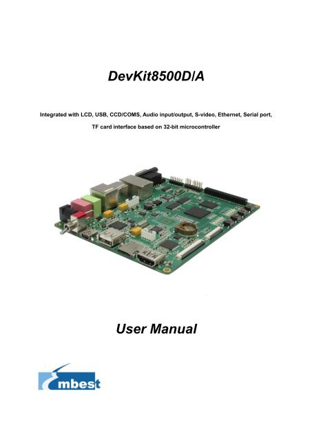
<strong>DevKit8500D</strong>/A<br />
Integrated with LCD, USB, CCD/COMS, Audio input/output, S-video, Ethernet, Serial port,<br />
TF card interface based on 32-bit microcontroller<br />
<strong>User</strong> <strong>Manual</strong>
COPYRIGHT<br />
<br />
Devkit8500D/A, CAM8000-A, CAM8000-D, GPRS8000-S, GPS8000-S, WCDMA8000-U,<br />
CDMA8000-U, WF8000-U, CAM8100-U, VGA8000 are trademarks of Embest Info&Tech<br />
Co.,LTD.<br />
<br />
<br />
<br />
AM3715, DM3730 are trademarks of TI Corporation.<br />
Sourcery G++ Lite <strong>for</strong> ARM GNU/Linux is a trademark of Codesourcery.<br />
Microsoft, MS-DOS, Windows, Windows95, Windows98, Windows2000, Windows<br />
embedded CE 6.0 are trademarks of Microsoft Corporation.<br />
Important Notice<br />
Embest has ownership and rights to the use of this Document.<br />
In<strong>for</strong>mation in the Document is within the protection of copyright. Unless specifically<br />
allowed, any part of this Document should not be modified, issued or copied in any manner<br />
or <strong>for</strong>m without prior written approval of Embest Info&Tech Co.,LTD.<br />
2
Version update records:<br />
Rev Date Description<br />
1.0 2011.6.20 Initial version<br />
1.1 2011.8.5 Parts of contents have been amended to avoid<br />
ambiguity<br />
1.2 2011.10.24 Modified part of name from schematic<br />
3
Contact:<br />
If you want to order products from Embest, please contact Marketing Department:<br />
Tel: +86-755-25635656 / 25636285<br />
Fax: +86-755-25616057<br />
E-mail: market@embedinfo.com<br />
If you want to get technical assistance from Embest, please contact Technical Assistance<br />
Department:<br />
Tel: +86-755-25503401<br />
E-mail: support@embedinfo.com<br />
URL: http://www.armkits.com<br />
Address: Room 509, Luohu Science&Technology Building, #85 Taining Road, Shenzhen,<br />
Guangdong, China (518020)<br />
4
Contents<br />
CHAPTER 1 OVERVIEW ................................................................................................................. 9<br />
1.1 PRODUCT INTRODUCTION .......................................................................................................... 9<br />
1.2 FEATURES .............................................................................................................................. 10<br />
CHAPTER 2 HARDWARE SYSTEM ............................................................................................. 13<br />
2.1 CPU ....................................................................................................................................... 13<br />
2.1.1 CPU Introduction ............................................................................................................ 13<br />
2.1.2 CPU Features ................................................................................................................ 13<br />
2.2 DESCRIPTION OF DIFFERENT IC BLOCKS .................................................................................. 15<br />
2.2.1 TPS65930 ...................................................................................................................... 15<br />
2.2.2 MT29C4G96MAZAPCJA-5 ............................................................................................ 16<br />
2.2.3 DM9000 .......................................................................................................................... 16<br />
2.2.4 FE1.1 <strong>for</strong> USB 2.0 High Speed 4-Port Hub ................................................................... 16<br />
2.2.5 TFP410 ........................................................................................................................... 17<br />
2.2.6 MAX3232 ....................................................................................................................... 17<br />
2.3 HARDWARE INTERFACE ........................................................................................................... 18<br />
2.3.1 Power Input Jack............................................................................................................ 18<br />
2.3.2 Power Output Interface .................................................................................................. 19<br />
2.3.3 Power Switch ................................................................................................................. 19<br />
2.3.4 S-VIDEO Interface ......................................................................................................... 19<br />
2.3.5 HDMI Interface ............................................................................................................... 19<br />
2.3.6 TFT_LCD Interface ........................................................................................................ 20<br />
2.3.7 AUDIO OUTPUT Jack .................................................................................................... 22<br />
2.3.8 Camera Interface ........................................................................................................... 22<br />
2.3.9 MIC IN Jack .................................................................................................................... 23<br />
2.3.10 Keyboard Interface ....................................................................................................... 24<br />
2.3.11 Serial Ports ................................................................................................................... 24<br />
2.3.12 LAN Interface ............................................................................................................... 25<br />
2.3.13 USB OTG Interface ...................................................................................................... 25<br />
2.3.14 USB HOST Interface .................................................................................................... 26<br />
5
2.3.15 TF Card Interface ......................................................................................................... 26<br />
2.3.16 JTAG Interface ............................................................................................................. 26<br />
2.3.17 Expansion Interface ..................................................................................................... 27<br />
2.3.18 KEY .............................................................................................................................. 28<br />
2.3.19 LED .............................................................................................................................. 28<br />
CHAPTER 3 LINUX OPERATING SYSTEM ................................................................................. 30<br />
3.1 INTRODUCTION........................................................................................................................ 30<br />
3.2 SOFTWARE RESOURCES ......................................................................................................... 30<br />
3.3 SOFTWARE FEATURES ............................................................................................................ 31<br />
3.4 SYSTEM DEVELOPMENT .......................................................................................................... 32<br />
3.4.1 Establishing operating system, development environment ........................................... 32<br />
3.4.2 System compilation ........................................................................................................ 33<br />
3.4.3 System Customization ................................................................................................... 37<br />
3.5 INTRODUCTION OF DRIVER ....................................................................................................... 39<br />
3.5.1 NAND ............................................................................................................................. 39<br />
3.5.2 SD/MMC ......................................................................................................................... 40<br />
3.5.3 Display interface............................................................................................................. 41<br />
3.5.4 Video capture ................................................................................................................. 42<br />
3.5.5 Audio in/out .................................................................................................................... 44<br />
3.6 DRIVER DEVELOPMENT ........................................................................................................... 45<br />
3.6.1 Driver For The gpio_keys ............................................................................................... 45<br />
3.6.2 Driver <strong>for</strong> the gpio_leds .................................................................................................. 51<br />
3.7 UPDATED OF SYSTEM .............................................................................................................. 56<br />
3.7.1 Update of TF card system image ................................................................................... 56<br />
3.7.2 Update of NAND Flash .................................................................................................. 60<br />
3.8 INSTRUCTIONS ........................................................................................................................ 62<br />
3.8.1 Various Tests senario ..................................................................................................... 62<br />
3.8.2 Demo .............................................................................................................................. 71<br />
3.9 THE DEVELOPMENT OF APPLICATION ....................................................................................... 78<br />
CHAPTER 4 WINCE OPERATING SYSTEM ................................................................................ 80<br />
6
4.1 INTRODUCTION........................................................................................................................ 80<br />
4.2 SOFTWARE RESOURCES ......................................................................................................... 80<br />
4.3 FEATURES .............................................................................................................................. 81<br />
4.4 SYSTEM DEVELOPMENT .......................................................................................................... 82<br />
4.4.1 Installation of IDE(Integrated Development Environment) ............................................ 82<br />
4.4.2 Extract BSP and project files to IDE .............................................................................. 83<br />
4.4.3 Sysgen & BSP compile .................................................................................................. 84<br />
4.4.4 Introduction of driver ...................................................................................................... 84<br />
MICROSOFT VISUAL STUDIO 2005-> ........................................................................................ 86<br />
4.5 UPDATE SYSTEM IMAGE .......................................................................................................... 87<br />
4.5.1 Update TF card Image ................................................................................................... 87<br />
4.5.2 Update Nand flash Image .............................................................................................. 89<br />
4.6 INSTRUCTIONS FOR USE .......................................................................................................... 90<br />
4.6.1 How to use S-Video interface ........................................................................................ 90<br />
4.6.2 How to use openGL ES demo ....................................................................................... 90<br />
4.6.3 How to use CAM8000-A module .................................................................................... 90<br />
4.6.4 How to use CAM8000-D module ................................................................................... 91<br />
4.7 THE DEVELOPMENT OF APPLICATION ........................................................................................ 91<br />
4.7.1 Application program interfaces and examples ............................................................... 91<br />
4.7.2 GPIO application program interfaces and examples ..................................................... 92<br />
APPENDIX ..................................................................................................................................... 95<br />
APPENDIX I HARDWARE DIMENSIONS ............................................................................................. 95<br />
APPENDIX II THE INSTALLATION OF UBUNTU .................................................................................. 96<br />
APPENDIX III DRIVER INSTALLATION OF LINUX USB ETHERNET/RNDIS GADGET .......................... 109<br />
APPENDIX IV LINUX BOOT DISK FORMAT ...................................................................................... 112<br />
APPENDIX V THE SETUP OF TFTP SERVER .................................................................................. 118<br />
APPENDIX VI WINCE SOURCE .................................................................................................... 120<br />
TECHNICAL SUPPORT & WARRANTY SERVICE .................................................................... 121<br />
TECHNICAL SUPPORT SERVICE .................................................................................................... 121<br />
7
MAINTENANCE SERVICE CLAUSE .................................................................................................. 122<br />
BASIC NOTICE TO PROTECT AND MAINTENANCE LCD .................................................................... 123<br />
VALUE ADDED SERVICES ............................................................................................................. 123<br />
8
Chapter 1 Overview<br />
1.1 Product introduction<br />
<strong>DevKit8500D</strong>/A is based on TI DM3730/AM3715 processor. The processor integrates ARM<br />
Cortex-A8 kernel at 1GHz and DSP core (DM3730 only) running at 800MHz with high-level<br />
digital signal processing functions, and provides rich peripheral interfaces. <strong>DevKit8500D</strong>/A<br />
expands LAN port, S-VIDEO interface, audio input/output interface, USB, TF interface, serial port,<br />
SPI interface, IIC interface, JTAG interface, CAMERA interface, TFT interface, touch screen<br />
interface, keyboard interface and HDMI interface.<br />
<strong>DevKit8500D</strong>/A can be used in the following applications:<br />
• Portable Data Terminals<br />
• Navigation<br />
• Auto Infotainment<br />
• Gaming<br />
• Medical Equipment<br />
• Home Automation<br />
• Human Interface<br />
• Industrial Control<br />
• Test and Measurement<br />
• Single board Computers<br />
9
<strong>DevKit8500D</strong>/A function module chart: (See Figure 1.1)<br />
Figure 1.1<br />
1.2 Features<br />
<strong>DevKit8500D</strong>/A evaluation board is based on DM3730/AM3715 processor and it integrates all the<br />
functions and features of this IC’s. The features of this board are as follows:<br />
Mechanical Parameters<br />
• Working temperature: -30°C ~ 70°C<br />
• Humidity Range: 20% ~ 90%<br />
• Dimensions: 136.2mm*105.3mm<br />
• Input Voltage: +5V<br />
Processor<br />
• 1GHz ARM Cortex-A8 Core<br />
• 800-MHz TMS320C64x+ DSP Core (DM3730 only)<br />
• NEON SIMD Coprocessor<br />
• POWERVR SGX Graphics Accelerator<br />
• ARM: 32 KB I-Cache; 32 KB D-Cache; 256KB L2 Cache<br />
• On Chip: 64KB RAM; 32KB ROM<br />
Memory<br />
10
• 512MB 32bit DDR SDRAM<br />
• 512MB 16bit NAND Flash<br />
• 2GB 4bit iNAND (Default: not soldered, optional, reserved <strong>for</strong> soldering)<br />
Audio/Video Interfaces<br />
• An S-VIDEO interface<br />
• An HDMI (DVI-D) interface<br />
• An audio input interface (3.5mm audio jack)<br />
• A two-channel audio output interface (3.5mm audio jack)<br />
LCD/Touch screen<br />
• RGB, 24 bit colors<br />
• Resolution up to 2048*2048<br />
• 4 line Touch Screen<br />
Data Transfer Interface<br />
• Serial port:<br />
• UART1, 5 line serial port, TTL based voltage<br />
• UART2, 5 line serial port, TTL based voltage<br />
• UART3, 5 line serial port, RS232 based voltage<br />
• USB port:<br />
• 1 x USB2.0 OTG, High-speed, 480Mbps<br />
• 4 x USB2.0 HOST, High-speed, 480Mbps<br />
• TF card interface<br />
• 10/100Mbps Ethernet Interface (RJ45 jack)<br />
• 1 channel McSPI Interface (Multichannel Serial Port Interface)<br />
• 1 channel McBSP interface (Multi-Channel Buffered Serial Port)<br />
• 1 channel I2C interface<br />
• 1 channel HDQ interface (HDQ/1-Wire)<br />
Input Interface<br />
• 1 channel Camera interface (Support CCD or CMOS camera)<br />
• 6*6 keyboard interface<br />
• 14-pin JTAG interface<br />
• 4 buttons (2 USER buttons, 1 RESET button, 1 ON/OFF button)<br />
11
LED<br />
• 1 Power LED<br />
• 2 System LEDs<br />
• 2 <strong>User</strong> LEDs<br />
• 4 USB Host LEDs<br />
• 1 USB Hub LED<br />
12
Chapter 2 Hardware System<br />
2.1 CPU<br />
2.1.1 CPU Introduction<br />
As a high-per<strong>for</strong>mance processor <strong>for</strong> enhanced digital media, DM37x/AM37x employs TI 45nm<br />
advanced industrial technology; this architecture has the advantage of low power consumption at<br />
the same time of being designed <strong>for</strong> ARM and graphical demonstration.<br />
The Texas Instruments’ DM3730 DaVinci digital media processor is powered by up to 1-GHz<br />
(also supports 300, 600, and 800-MHz operation) ARM Cortex-A8 and 800-MHz (also supports<br />
250, 520 and 660-MHz operation) C64x+ DSP core, and has integrated 3D graphics processor,<br />
imaging and video accelerator (IVA), USB 2.0, MMC/SD memory card, UART and many more.<br />
DaVinci DM3730 video processor is pin-to-pin compatible with Sitara AM37x devices and software<br />
compatible with the OMAP35x processors. The C64x+ DSP and hardware video accelerator<br />
enable audio and HD 720p video decoding and encoding independent of the ARM processor. The<br />
programmable DSP engine allows multiple signal processing tasks such as image processing and<br />
analysis, digital filtering, and math functions. DaVinci DM3730 video processor is suitable <strong>for</strong> 720p<br />
HD (High Definition) video applications which require large amount of data processing.<br />
2.1.2 CPU Features<br />
Clock<br />
The CPU clock includes sys_32k, sys_altclk, sys_clkout1, sys_clkout2, sys_xtalout, sys_xtalin,<br />
sys_clkreq.<br />
The sys_32k 32-kHz clock is used <strong>for</strong> low frequency operation. It supplies the wake-up domain<br />
signals <strong>for</strong> operating in lowest power mode (off mode). This clock is provided through the sys_32k<br />
pin. The 32-kHz is generated by power management.<br />
The sys_xtalin / sys_xtalout system input clock (26 MHz) is used to generate the main source<br />
clock <strong>for</strong> the device. It supplies the DPLLs as well to several other modules.<br />
13
Reset<br />
The function of reset is decided by the SYS_NRESPWRON signal on the CPU, Reset is enabled<br />
when LOW level signal (high to low) is given.<br />
General-Purpose Interface<br />
The general-purpose interface combines six general-purpose input/output (GPIO) banks.<br />
Each GPIO bank provides 32 dedicated general-purpose pins with input and output capabilities;<br />
thus, it supports up to 192 (6 x 32) general-purpose interface pins.<br />
These pins can be configured <strong>for</strong> the following applications:<br />
• Data input (capture)/output (drive)<br />
• Keyboard interface with a debounce cell<br />
• Interrupt generation in active mode when external events are detected.<br />
Display Subsystem<br />
The display subsystem provides the logic to display a video frame from the memory frame buffer<br />
(either SDRAM or SRAM) on a liquid-crystal display (LCD) panel or a TV set. The display<br />
subsystem integrates the following elements:<br />
• Display controller (DISPC) module<br />
• Remote frame buffer interface (RFBI) module<br />
• Display serial interface (DSI) complex I/O module and a DSI protocol engine<br />
• DSI PLL controller that drives a DSI PLL and high-speed (HS) divider.<br />
• NTSC/PAL video encoder<br />
The display controller and the DSI protocol engine are connected to the L3 and L4 interconnect;<br />
the RFBI and the TV out encoder modules are connected to the L4 interconnect.<br />
2D/3D Graphics Accelerator<br />
The 2D/3D graphics accelerator (SGX) subsystem accelerates 2-dimensional (2D) and<br />
3-dimensional (3D) graphics applications. The SGX subsystem is based on the POWERVR® SGX<br />
core from Imagination Technologies. SGX is a new generation of programmable POWERVR<br />
graphic cores. The POWERVR SGX530 v1.2.5 architecture is scalable and can target all market<br />
segments from mainstream mobile devices to high-end desktop graphics. Targeted applications<br />
14
include feature phone, PDA, and hand-held games. (see Figure 2.1.1)<br />
The SGX graphics accelerator can simultaneously process various multimedia data types:<br />
• Pixel data<br />
• Vertex data<br />
• Video data<br />
• General-purpose processing<br />
This is achieved through a multithreaded architecture using two levels of scheduling and data<br />
partitioning enabling zero-overhead task switching.<br />
2.2 Description of different IC blocks<br />
2.2.1 TPS65930<br />
The TPS65930 devices are power-management ICs <strong>for</strong> OMAP and other mobile applications.<br />
The devices include power-management, a universal serial bus (USB) high-speed (HS)<br />
transceiver, light-emitting diode (LED) drivers, an analog-to-digital converter (ADC), a real-time<br />
clock (RTC), and embedded power control (EPC). In addition, the TPS65930 includes a full audio<br />
codec with two digital-to-analog converters (DACs) and two ADCs to implement dual voice<br />
15
channels, and a stereo downlink channel that can play all standard audio sample rates through a<br />
multiple <strong>for</strong>mat inter-integrated sound (I2S)/time division multiplexing (TDM) interface.<br />
TPS65930(U1)is communicated with CPU through I2C protocol, the main function of this is to<br />
provide 1.2V and 1.8V to CPU, to make CPU run normally. Besides, TPS65930 also has functions<br />
of Audio in, Audio out, OTG PHY, Keyboard, ADC and GPIO.<br />
2.2.2 MT29C4G96MAZAPCJA-5<br />
As the storage chip of <strong>DevKit8500D</strong>/A, MT29C4G96MAZAPCJA-5 is a memory device used <strong>for</strong><br />
storage, it is integrated with NAND Flash and SDRAM DDR, its memory size is 512MB. NAND<br />
Flash realizes data access through GPMC bus, while DDR realizes data access through SDRAM<br />
Controller(SDRC).<br />
2.2.3 DM9000<br />
The DM9000A is a fully integrated and cost-effective low pin count single chip Fast Ethernet<br />
controller with a general processor interface, a 10/100M PHY and 4K Dword SRAM. It is designed<br />
with low power and high per<strong>for</strong>mance process that support 3.3V with 5V IO tolerance.<br />
<strong>DevKit8500D</strong>/A uses 10/100M adaptive network interface of DM9000, in which, the 10/100M<br />
Ethernet module is built-in and is compatible to IEEE 802.3 standard protocol. The cable interface<br />
is a standard RJ45, with a connection indicator and a transmission indicator.<br />
<strong>DevKit8500D</strong>/A can be connected to network hub through a direct cable, also can be directly<br />
connected with a computer through a crossover cable.<br />
2.2.4 FE1.1 <strong>for</strong> USB 2.0 High Speed 4-Port Hub<br />
The FE1.1 is a highly integrated, high quality, high per<strong>for</strong>mance, low power consumption, yet low<br />
cost solution <strong>for</strong> USB 2.0 High Speed 4-Port Hub.<br />
It adopts Multiple Transaction Translator (MTT) architecture to explore the maximum possible<br />
throughput. Six, instead of two, non-periodic transaction buffers are used to minimize potential<br />
traffic jamming.<br />
FE1.1 is link out the 4 channel USB interface via the USB3320, share one channel 480Mbps as<br />
four channel 120Mbps. Support High-Speed (480MHz), Full-Speed (12MHz), and Low-Speed<br />
(1.5MHz) modes.<br />
16
2.2.5 TFP410<br />
The TFP410 is a Texas Instruments PanelBus flat panel display product, part of a comprehensive<br />
family of end-to-end DVI 1.0-compliant solutions, targeted at the PC and consumer electronics<br />
industry.<br />
The TFP410 provides a universal interface to allow a glue-less connection to most commonly<br />
available graphics controllers. Some of the advantages of this universal interface include<br />
selectable bus widths, adjustable signal levels, and differential and single-ended clocking. The<br />
adjustable 1.1-V to 1.8-V digital interface provides a low-EMI, high-speed bus that connects<br />
seamlessly with 12-bit or 24-bit interfaces. The DVI interface supports flat panel display<br />
resolutions up to UXGA at 165 MHz in 24-bit true color pixel <strong>for</strong>mat.<br />
2.2.6 MAX3232<br />
The function of MAX3232 is mainly to translate TTL logic level signal into RS232 logic level, which<br />
helps in communicating the board with PC.<br />
<strong>DevKit8500D</strong>/A uses UART3 as debugging serial port; as the default voltage of UART3 is 1.8V, it<br />
is necessary to convert this voltage to 3.3V in order to connect to eternal world.<br />
17
2.3 Hardware interface<br />
Figure 2.3 <strong>DevKit8500D</strong>/A Hardware Interface Diagram<br />
The following section gives in detail about the pin numbers and its function description of various<br />
different IC’s blocks present in <strong>DevKit8500D</strong>/A.<br />
2.3.1 Power Input Jack<br />
J19<br />
Pin Signal Function<br />
1 GND GND<br />
2 +5V Power supply (+5V) 2A (Type)<br />
Table 2-3-1 power input interface<br />
18
2.3.2 Power Output Interface<br />
J4<br />
Pin Signal Function<br />
1 VDD50 5V output<br />
2 NC NC<br />
3 VDD33 3.3V output<br />
4 ADCIN ADC input<br />
5 GND GND<br />
Table 2-3-2 power output interface<br />
2.3.3 Power Switch<br />
SW1<br />
Pin Signal Function<br />
1 DC IN VDD Input<br />
2 VDD50 +5V<br />
3 NC NC<br />
Table 2-3-3 power switch<br />
2.3.4 S-VIDEO Interface<br />
J4<br />
Pin Signal Function<br />
1 GND GND<br />
2 GND GND<br />
3 OUTPUT1 VIDEO Y<br />
4 OUTPUT2 VIDEO C<br />
Table 2-3-4 S-VIDEO interface<br />
2.3.5 HDMI Interface<br />
J12<br />
19
Pin Signal Function<br />
1 DAT2+ TMDS data 2+<br />
2 DAT2_S TMDS data 2 shield<br />
3 DAT2- TMDS data 2-<br />
4 DAT1+ TMDS data 1+<br />
5 DAT1_S TMDS data 1 shield<br />
6 DAT1- TMDS data 1-<br />
7 DAT0+ TMDS data 0+<br />
8 DAT0_S TMDS data 0 shield<br />
9 DAT0- TMDS data 0-<br />
10 CLK+ TMDS data clock+<br />
11 CLK_S TMDS data clock shield<br />
12 CLK- TMDS data clock-<br />
13 CEC Consumer Electronics Control<br />
14 NC NC<br />
15 SCL IIC master serial clock<br />
16 SDA IIC serial bidirectional data<br />
17 GND GND<br />
18 5V 5V<br />
19 HPLG Hot plug and play detect<br />
Table 2-3-5 HDMI interface<br />
2.3.6 TFT_LCD Interface<br />
J12<br />
Pin Signal Function<br />
1 DSS_D0 LCD Pixel data bit 0<br />
2 DSS_D1 LCD Pixel data bit 1<br />
3 DSS_D2 LCD Pixel data bit 2<br />
4 DSS_D3 LCD Pixel data bit 3<br />
5 DSS_D4 LCD Pixel data bit 4<br />
6 DSS_D5 LCD Pixel data bit 5<br />
7 DSS_D6 LCD Pixel data bit 6<br />
20
8 DSS_D7 LCD Pixel data bit 7<br />
9 GND GND<br />
10 DSS_D8 LCD Pixel data bit 8<br />
11 DSS_D9 LCD Pixel data bit 9<br />
12 DSS_D10 LCD Pixel data bit 10<br />
13 DSS_D11 LCD Pixel data bit 11<br />
14 DSS_D12 LCD Pixel data bit 12<br />
15 DSS_D13 LCD Pixel data bit 13<br />
16 DSS_D 14 LCD Pixel data bit 14<br />
17 DSS_D15 LCD Pixel data bit 15<br />
18 GND GND<br />
19 DSS_D16 LCD Pixel data bit 16<br />
20 DSS_D17 LCD Pixel data bit 17<br />
21 DSS_D18 LCD Pixel data bit 18<br />
22 DSS_D19 LCD Pixel data bit 19<br />
23 DSS_D20 LCD Pixel data bit 20<br />
24 DSS_D21 LCD Pixel data bit 21<br />
25 DSS_D22 LCD Pixel data bit 22<br />
26 DSS_D23 LCD Pixel data bit 23<br />
27 GND GND<br />
28 DEN AC bias control (STN) or pixel data enable (TFT)<br />
29 HSYNC LCD Horizontal Synchronization<br />
30 VSYNC LCD Vertical Synchronization<br />
31 GND GND<br />
32 CLK LCD Pixel Clock<br />
33 GND GND<br />
34 X+ X+ Position Input<br />
35 X- X- Position Input<br />
36 Y+ Y+ Position Input<br />
37 Y- Y- Position Input<br />
38 SPI_CLK SPI clock<br />
39 SPI_MOSI Slave data in, master data out<br />
21
40 SPI_MISO Slave data out, master data in<br />
41 SPI_CS SPI enable<br />
42 IIC_CLK IIC master serial clock<br />
43 IIC_SDA IIC serial bidirectional data<br />
44 GND GND<br />
45 VDD18 1.8V<br />
46 VDD33 3.3V<br />
47 VDD50 5V<br />
48 VDD50 5V<br />
49 RESET Reset<br />
50 PWREN Power on enable<br />
Table 2-3-6 TFT_LCD interface<br />
2.3.7 AUDIO OUTPUT Jack<br />
J7<br />
Pin Signal Function<br />
1 GND GND<br />
2 NC NC<br />
3 Right Right output<br />
4 NC NC<br />
5 Left Left output<br />
Table 2-3-7 Audio out interface<br />
2.3.8 Camera Interface<br />
J14<br />
Pin Signal Function<br />
1 GND GND<br />
2 D0 Digital image data bit 0<br />
3 D1 Digital image data bit 1<br />
4 D2 Digital image data bit 2<br />
5 D3 Digital image data bit 3<br />
6 D4 Digital image data bit 4<br />
22
7 D5 Digital image data bit 5<br />
8 D6 Digital image data bit 6<br />
9 D7 Digital image data bit 7<br />
10 D8 Digital image data bit 8<br />
11 D9 Digital image data bit 9<br />
12 D10 Digital image data bit 10<br />
13 D11 Digital image data bit 11<br />
14 GND GND<br />
15 PCLK Pixel clock<br />
16 GND GND<br />
17 HS Horizontal synchronization<br />
18 VDD50 5V<br />
19 VS Vertical synchronization<br />
20 VDD33 3.3V<br />
21 XCLKA Clock output a<br />
22 XCLKB Clock output b<br />
23 GND GND<br />
24 FLD Field identification<br />
25 WEN Write Enable<br />
26 STROBE Flash strobe control signal<br />
27 SDA IIC master serial clock<br />
28 SCL IIC serial bidirectional data<br />
29 GND GND<br />
30 VDD18 1.8V<br />
Table 2-3-8 camera interface<br />
2.3.9 MIC IN Jack<br />
J6<br />
Pin Signal Function<br />
1 GND GND<br />
2 NC NC<br />
3 MIC MAIN P Right input<br />
23
4 NC NC<br />
5 MIC MAIN N Left input<br />
Table 2-3-9 MIC IN interface<br />
2.3.10 Keyboard Interface<br />
J5<br />
Pin Signal Function<br />
1 KC0 Keypad matrix column 0 output<br />
2 KR0 Keypad matrix row 0 input<br />
3 KC1 Keypad matrix column 1 output<br />
4 KR1 Keypad matrix row 1 input<br />
5 KC2 Keypad matrix column 2 output<br />
6 KR2 Keypad matrix row 2 input<br />
7 KC3 Keypad matrix column 3 output<br />
8 KR3 Keypad matrix row 3 input<br />
9 KC4 Keypad matrix column 4 output<br />
10 KR4 Keypad matrix row 4 input<br />
11 KC5 Keypad matrix column 5 output<br />
12 KR5 Keypad matrix row 5 input<br />
13 VDD18 1.8V<br />
14 GND GND<br />
Table 2-3-10 keyboard interface<br />
2.3.11 Serial Ports<br />
J15<br />
Pin Signal Function<br />
1 NC NC<br />
2 RXD Receive data<br />
3 TXD Transit data<br />
4 NC NC<br />
5 GND GND<br />
24
6 NC NC<br />
7 RTS Request To Send<br />
8 CTS Clear To Send<br />
9 NC NC<br />
Table 2-3-11 serial port<br />
2.3.12 LAN Interface<br />
J13<br />
Pin Signal Function<br />
1 TX+ TX+ output<br />
2 TX- TX- output<br />
3 RX+ RX+ input<br />
4 VDD25 2.5V Power <strong>for</strong> TX/RX<br />
5 VDD25 2.5V Power <strong>for</strong> TX/RX<br />
6 RX- RX- input<br />
7 NC NC<br />
8 NC NC<br />
9 VDD 3.3V Power <strong>for</strong> LED<br />
10 LED1 Speed LED<br />
11 LED2 Link LED<br />
12 VDD 3.3V Power <strong>for</strong> LED<br />
Table 2-3-12 LAN interface<br />
2.3.13 USB OTG Interface<br />
J16<br />
Pin Signal Function<br />
1 VBUS +5V<br />
2 DN USB Data-<br />
3 DP USB Data+<br />
4 ID USB ID<br />
5 GND GND<br />
Table 2-3-13 USB OTG interface<br />
25
2.3.14 USB HOST Interface<br />
J17<br />
Pin Signal Function<br />
1 VBUS +5V<br />
2 DN USB Data-<br />
3 DP USB Data+<br />
4 ID USB ID<br />
Table 2-3-14 USB HOST interface<br />
2.3.15 TF Card Interface<br />
J3<br />
Pin Signal Function<br />
1 DAT2 Card data 2<br />
2 DAT3 Card data 3<br />
3 CMD Command Signal<br />
4 VDD VDD<br />
5 CLK Clock<br />
6 VSS VSS<br />
7 DAT0 Card data 0<br />
8 DAT1 Card data 1<br />
9 CD Card detect<br />
Table 2-3-15 TF interface<br />
2.3.16 JTAG Interface<br />
J2<br />
Pin Signal Function<br />
1 TMS Test mode select<br />
2 NTRST Test system reset<br />
3 TDI Test data input<br />
4 GND GND<br />
5 VIO 1.8V<br />
6 NC NC<br />
7 TDO Test data output<br />
8 GND GND<br />
26
9 RTCK Receive test clock<br />
10 GND GND<br />
11 TCK Test clock<br />
12 GND GND<br />
13 EMU0 Test emulation 0<br />
14 EMU1 Test emulation 1<br />
Table 2-3-16 JTAG interface<br />
2.3.17 Expansion Interface<br />
J8<br />
Pin Signal Function<br />
1 GND GND<br />
2 BSP1_DX Transmitted serial data 1<br />
3 BSP1_DR Received serial data 1<br />
4 BSP1_CLK<br />
Received clock 1<br />
5 R BSP1_FSX Transmit frame synchronization 1<br />
6 BSP1_CLK Transmit clock 1<br />
7 X BSP1_CLK External clock input 1<br />
8 S BSP1_FSR Receive frame synchronization 1<br />
9 UART1_CT UART1 clear to send<br />
10 S UART1_RT UART1 request to send<br />
11 S UART1_RX UART1 receive data<br />
12 UART1_TX UART1 transmit data<br />
13 GND GND<br />
14 GPIO_136 GPIO_136<br />
15 GPIO_126 GPIO_126<br />
16 GPIO_137 GPIO_137<br />
17 GPIO_129 GPIO_129<br />
18 GPIO_138 GPIO_138<br />
19 GPIO_55 GPIO_55<br />
20 GPIO_139 GPIO_139<br />
21 GPIO_56 GPIO_56<br />
22 GPIO_61 GPIO_61<br />
23 GPIO_65 GPIO_65<br />
24 BSP3_DX Transmitted serial data 3<br />
25 BSP3_DR Received serial data 3<br />
27
26 BSP3_CLK Transmit clock 3<br />
27 X BSP3_FSX Transmit frame synchronization 3<br />
28 GND GND<br />
29 IIC3_SCL IIC3 master serial clock<br />
30 IIC3_SDA IIC3 serial bidirectional data<br />
31 SPI1_SIMO Slave data in, master data out<br />
32 SPI1_SOMI Slave data out, master data in<br />
33 SPI1_CLK SPI1 clock<br />
34 SPI1_CS0 SPI enable 0<br />
35 SPI1_CS3 SPI enable 3<br />
36 HDQ_SIO Bidirectional HDQ<br />
37 VDD33 3.3V<br />
38 VDD18 1.8V<br />
39 VDD50 5V<br />
40 GND GND<br />
Table 2-3-17 expansion interface<br />
2.3.18 KEY<br />
J8<br />
Pin Signal Function<br />
1 ON/OFF System ON/OFF key<br />
2 RESET System reset key<br />
3 USER1 <strong>User</strong>-defined key 1<br />
4 USER2 <strong>User</strong>-defined key 2<br />
Table 2-3-18 KEY<br />
2.3.19 LED<br />
LED 1-10<br />
Pin Signal Function<br />
LED1 3V3 3.3V power indicator<br />
LED 2 SYS System LED<br />
LED 3 LEDB System LED<br />
LED 4 LED1 <strong>User</strong>-defined key 1<br />
LED 5 LED2 <strong>User</strong>-defined key 2<br />
28
LED 6 USB1 USB indicator 1<br />
LED 7 USB2 USB indicator 2<br />
LED 8 USB3 USB indicator 3<br />
LED 9 USB4 USB indicator 4<br />
LED 10 HUB USB HUB indicator<br />
Table 2-3-19 LED<br />
29
Chapter 3 Linux Operating System<br />
3.1 Introduction<br />
This section is intended to provide detailed instruction on Operating System Software<br />
development of <strong>DevKit8500D</strong>/A board.<br />
1) Describes the Software Resources provided by <strong>DevKit8500D</strong>/A.<br />
2) Describes the software feature.<br />
3) Explains the software Development including how to set up the development environment, the<br />
building guidance of the boot loader, kernel and file system, and the development of device driver.<br />
4) Provides flashing methods using boot loader commands.<br />
5) Shows the usage of <strong>DevKit8500D</strong>/A<br />
6) Shows the application development.<br />
In this part, it is suggested to:<br />
1) Install Ubuntu Linux in advance, please refer to Appendix II <strong>for</strong> details;<br />
2) Master relative embedded Linux development technology.<br />
3.2 Software Resources<br />
This chapter provides an overview of software system components of <strong>DevKit8500D</strong>/A. A basic<br />
software system consists of four parts: x-loader, u-boot, kernel and rootfs. The Figure 3.2.1 shows<br />
the structure of the system:<br />
Figure 3.2.1<br />
Features and functions of each part of the system are given below:<br />
30
1) X-loader is a first level bootstrap program. After the system start-up, the ROM inside the CPU<br />
will copy the x-loader to internal RAM and per<strong>for</strong>m its routine work. Its main function is to initialize<br />
the CPU, copy u-boot into the memory and give the control to u-boot;<br />
2) U-boot is a second level bootstrap program. It is used <strong>for</strong> interacting with users and updating<br />
images and leading the kernel;<br />
3) The latest 2.6.x kernel is employed here and it can be customized based on <strong>DevKit8500D</strong>/A;<br />
4) Rootfs employs Open-source system. It is small in capacity and powerful, very suitable <strong>for</strong><br />
embedded systems;<br />
3.3 Software Features<br />
Item<br />
Note<br />
NAND / ONENAND<br />
x-loader<br />
MMC/SD<br />
FAT<br />
BIOS<br />
NAND / ONENAND<br />
u-boot<br />
MMC/SD<br />
FAT<br />
Kernel<br />
Device Driver<br />
Linux-2.6.x<br />
Serial<br />
Rtc<br />
Net<br />
Flash<br />
LCD<br />
Touch<br />
screen<br />
mmc/sd<br />
usb otg<br />
NET<br />
Supports ROM/CRAM/EXT2/EXT3/FAT/NFS/<br />
JFFS2/UBIFS and various file systems<br />
Series driver<br />
Hardware clock driver<br />
10/100M Ethernet card DM9000 driver<br />
nand flash driver (supports nand boot)<br />
TFT LCD driver<br />
Touch screen controller ads7846 driver<br />
mmc/sd controller driver<br />
usb otg 2.0 driver (can be configured as slave<br />
device currently)<br />
31
Demo<br />
usb ehci<br />
Dvi<br />
s-video<br />
Audio<br />
Camera<br />
Keypad<br />
Led<br />
Android<br />
DVSDK<br />
usb ehci driver<br />
Supports dvi-d signal output<br />
Supports s-video signal output<br />
Audio driver<br />
Camera driver<br />
6x6 matrix keyboard driver<br />
<strong>User</strong> led lamp driver<br />
android 2.2 system<br />
DVSDK 4_00_00_22<br />
Table 3-3-1<br />
3.4 System Development<br />
3.4.1 Establishing operating system, development environment<br />
Be<strong>for</strong>e executing software development on <strong>DevKit8500D</strong>/A, the user has to establish a Linux<br />
cross development environment and install it in computer. How to establish a cross development<br />
environment will be introduced below by taking Ubuntu operating system as an example.<br />
3.4.1.1 Installation of cross compilation tools<br />
Installation of cross compilation tools is done by using the software CD provided along with this kit,<br />
to start the process insert the CD and allow it <strong>for</strong> auto run, Ubuntu will mount the disc under the<br />
directory /media/cdrom, the cross compilation tools are saved under the directory<br />
/media/cdrom/linux/tools.<br />
The following instructions are executed at the Ubuntu terminal to decompress the cross<br />
compilation tools under the directory /home/embest:<br />
cd /media/cdrom/linux/tools<br />
tar xvf arm-eabi-4.4.0.tar.bz2 -C /home/embest<br />
tar xvf arm-2007q3.tar.bz2 -C /home/embest<br />
Some of the other development tools used <strong>for</strong> source code compilation are present in the directory<br />
linux/tools of the disc; the user can execute the following commands to copy them to local folder:<br />
mkdir /home/embest/tools<br />
32
cp /media/cdrom/linux/tools/mkimage /home/embest/tools<br />
cp /media/cdrom/linux/tools/signGP /home/embest/tools<br />
cp /media/cdrom/linux/tools/mkfs.ubifs /home/embest/tools<br />
cp /media/cdrom/linux/tools/ubinize /home/embest/tools<br />
cp /media/cdrom/linux/tools/ ubinize.cfg /home/embest/tools<br />
It is defaulted to install it under the user directory that is subject to<br />
/home/embest in the text; the user can change it to his directory properly.<br />
3.4.1.2 Addition of environment variables<br />
After all above tools are installed, it is necessary to use the following commands to add them in the<br />
temporary environment variables:<br />
export PATH=/home/embest/arm-eabi-4.4.0/bin:/home/embest/tools:$PATH<br />
The user can write it in the .barsrc file under the user directory, such that<br />
the addition of environment variables will be finished automatically when<br />
the system is booted; command echo $PATH can be used to check the<br />
path.<br />
3.4.2 System compilation<br />
3.4.2.1 Preparation<br />
Source codes of all components of the system are under the directory linux/source in the disc;<br />
user has to decompress them to the Ubuntu system be<strong>for</strong>e executing development:<br />
mkdir /home/embest/work<br />
cd /home/embest/work<br />
tar xvf /media/cdrom/linux/source/x-loader-03.00.02.07.tar.bz2<br />
tar xvf /media/cdrom/linux/source/u-boot-03.00.02.07.tar.bz2<br />
tar xvf /media/cdrom/linux/source/linux-2.6.32-devkit8500.tar.bz2<br />
tar<br />
xvf<br />
/media/cdrom/linux/demo/Android/source/rowboat-android-froyo-devkit8500.tar.bz2<br />
sudo tar xvf /media/cdrom/linux/source/rootfs.tar.bz2<br />
33
When the above steps are finished, the current directory will generate linux-2.6.32-devkit8500,<br />
u-boot-03.00.02.07, x-loader-03.00.02.07, rootfs and rowboat-android-froyo-devkit8500<br />
directories.<br />
3.4.2.2 X-loader image generation<br />
DevKit8500 supports TF Card boot or NAND boot. The burned x-loader image files are different<br />
with the different boot modes, and the corresponding methods <strong>for</strong> mapping are different too.<br />
We will introduce the generation of x-loader image file under different boot modes.<br />
1) To generate x-loader image file MLO used <strong>for</strong> SD card start-up<br />
cd x-loader-03.00.02.07<br />
make distclean<br />
make devkit8500_config<br />
make<br />
signGP x-load.bin<br />
mv x-load.bin.ift MLO<br />
When the above steps are finished, the current directory will generate the file MLO which we need.<br />
2) To generate the x-load.bin.ift_<strong>for</strong>_NAND start-up<br />
To alter the file x-loader-03.00.02.07/include/configs/devkit8500.h and annotate the following:<br />
vi x-loader-03.00.02.07/include/configs/devkit8500.h<br />
// #define CONFIG_MMC 1<br />
Cross compilation:<br />
cd x-loader-03.00.02.07<br />
make distclean<br />
make devkit8500_config<br />
make<br />
signGP x-load.bin<br />
mv x-load.bin.ift x-load.bin.ift_<strong>for</strong>_NAND<br />
When the above steps are finished, the current directory will generate the file<br />
x-load.bin.ift_<strong>for</strong>_NAND which we need.<br />
3.4.2.3 U-boot image generated<br />
cd u-boot-03.00.02.07<br />
34
make distclean<br />
make devkit8500_config<br />
make<br />
When the above steps are finished, the current directory will generate the file u-boot.bin which we<br />
need.<br />
3.4.2.4 Kernel compilation<br />
Be<strong>for</strong>e kernel compilation, the user has to select correct display according to the customize menu<br />
of kernel:<br />
For Linux system, the output operation is as follows:<br />
cd linux-2.6.32-devkit8500<br />
make distclean<br />
make devkit8500_defconfig<br />
make uImage<br />
For Android system, the iutput operation is as follows:<br />
cd linux-2.6.32-devkit8500<br />
make distclean<br />
make devkit8500_android_defconfig<br />
make menuconfig<br />
If an error occurs in the system when make menuconfig is input, it is<br />
necessary to install ncurse in the Ubuntu system; ncurse library is a<br />
character graphic library, used <strong>for</strong> make menuconfig of kernel; the specific<br />
installation instruction is:<br />
sudo apt-get install ncurses-dev<br />
Enter the kernel customize menu now, enter “PANEL_TYPE” according to the following pointing<br />
paths:<br />
35
Select under “PANEL_TYPE” according to actually displayed screen size:<br />
After determining “PANEL_TYPE”, jump to parent directory, select “Exit” to exit, until the following<br />
picture appears, then select “Yes”:<br />
make uImage<br />
After above operations are executed, the required uImage file will be generated under the<br />
directory arch/arm/boot.<br />
3.4.2.5 Generation of file system<br />
1) Ramdisk file making<br />
For Ramdisk making, please refer to http://he3.dartmouth.edu/old/VME-Linux/RamDisk.html.<br />
It will not be described in this document.<br />
2) UBI file making<br />
cd /home/embest/work<br />
sudo /home/embest/tools/mkfs.ubifs -r rootfs -m 2048 -e 129024 -c 1996 -o ubifs.img<br />
36
sudo /home/embest/tools/ubinize -o ubi.img -m 2048 -p 128KiB -s 512<br />
/home/embest/tools/ubinize.cfg<br />
After above operations are executed, the required ubi.img file will be generated under the current<br />
directory.<br />
3.4.2.6 Android compilation<br />
1) Input the following commands to compile Android:<br />
cd rowboat-android-froyo-devkit8500<br />
make<br />
2) Modified script file build_ubi.sh:<br />
vi build_ubi.sh<br />
Changed “/home/embest” as “$HOME”:<br />
MKFSUBI=/home/embest/tools/mkfs.ubifs<br />
MKFSUBI_ARG="-r ${ROOT_DIR} -m 2048 -e 129024 -c 4063 -o temp/ubifs.img"<br />
UBINIZE=/home/embest/tools/ubinize<br />
UBINIZECFG=/home/embest/tools/ubinize.cfg<br />
UBINIZE_ARG="-o ubi.img -m 2048 -p 128KiB -s 512 ${UBINIZECFG}"<br />
Modified as:<br />
MKFSUBI=$HOME/tools/mkfs.ubifs<br />
MKFSUBI_ARG="-r ${ROOT_DIR} -m 2048 -e 129024 -c 4063 -o temp/ubifs.img"<br />
UBINIZE=$HOME/tools/ubinize<br />
UBINIZECFG=$HOME/tools/ubinize.cfg<br />
UBINIZE_ARG="-o ubi.img -m 2048 -p 128KiB -s 512 ${UBINIZECFG}"<br />
3) Input the following commands to build file system:<br />
./build_ubi.sh<br />
File ubi.img will output under the folder out/target/product/devkit8500/rootfs.<br />
3.4.3 System Customization<br />
As Linux kernel has many kernel configuration options, the user can increase or reduce the driver<br />
or some kernel features based on the default configuration to meet the demands in better ways.<br />
The general process of system customization will be described with examples below.<br />
37
3.4.3.1 Modification of kernel configuration<br />
A default configuration file is provided in the factory kernel source codes:<br />
arch/arm/configs/devkit8500_defconfig<br />
<strong>User</strong> can carry out system customization on this basis:<br />
cd linux-2.6.32-devkit8500<br />
cp arch/arm/configs/devkit8500_defconfig .config<br />
make menuconfig<br />
The system customization will be described below by taking usb gadget and usb mass storage<br />
device as an example:<br />
Select the configuration below:<br />
-> Device Drivers<br />
-> USB support<br />
-> USB Gadget Support<br />
-> USB Gadget Drivers<br />
Select “File-backed Storage Gadget” as , exit, and finally select Save to recompile kernel.<br />
3.4.3.2 Compilation<br />
Save configuration, execute the following commands to recompile kernel:<br />
make uImage<br />
make modules<br />
After above operations are executed, a new kernel image uImage will be generated under the<br />
directory arch/arm/boot, and a module file g_file_storage.ko will be generated under the directory<br />
38
drivers/usb/gadget.<br />
3.5 Introduction of driver<br />
3.5.1 NAND<br />
App, System call<br />
<strong>User</strong><br />
VFS<br />
MTD user module<br />
JFFS2 JFFS Char device Block device<br />
Memory technology device<br />
Generic NAND driver<br />
Kernel<br />
MTD chip driver<br />
NAND flash<br />
chip<br />
driver<br />
CFI flash<br />
er<br />
driv<br />
RAM,ROM<br />
etc<br />
Chips<br />
GPMC module<br />
NAND flash<br />
Hardware<br />
Figure 3.5.1 Modular structure <strong>for</strong> NAND<br />
Solid-state memory used in embedded systems is mainly flash; it is NAND flash in this system.<br />
NAND flash is used as a block device, on which the file system is arranged; interaction between<br />
user and NAND flash is mainly realized by a specific file system. In order to shield difference in<br />
different flash memories, kernel inserts an MTD subsystem between the file system and the<br />
specific flash driver <strong>for</strong> management.<br />
There<strong>for</strong>e, the user accesses NAND flash through the following process:<br />
<strong>User</strong>->System Call->VFS->Block Device Driver->MTD->NAND Flash Driver->NAND Flash。<br />
39
Kernel Driver reference path:<br />
linux-2.6.32-devkit8500/drivers/mtd/nand/<br />
linux-2.6.32-devkit8500/drivers/mtd/nand/omap2.c<br />
3.5.2 SD/MMC<br />
App, System call<br />
Use<br />
r<br />
Kernel (Generic disk handler, File system)<br />
BUFFER_CACHE<br />
Kernel<br />
MMC_QUEUE<br />
MMC/SD CORE<br />
MMC_BLOCK<br />
MMC/SD CONTROLLER DRIVER<br />
HARDWARE (MMC/SD/SDIO CONTROLLER)<br />
Hardware<br />
Figure 3.5.2 Modular structure <strong>for</strong> SD/MMC<br />
SD/MMC card drivers under Linux mainly include SD/MMC core, mmc_block, mmc_queue and<br />
SD/MMC driver four parts:<br />
1) SD/MMC core realizes core codes unlated to structure in the SD/MMC card operation.<br />
2) mmc_block realizes driver structure when SD/MMC card is used as a block device.<br />
3) mmc_queue realizes management of request queue.<br />
4) SD/MMC driver realizes specific controller driver.<br />
Kernel Driver reference path:<br />
linux-2.6.32-devkit8500/drivers/mmc/<br />
linux-2.6.32-devkit8500/drivers/mmc/host/omap_hsmmc.c<br />
40
3.5.3 Display interface<br />
Control<br />
Application<br />
GUI<br />
Application<br />
Streamimg<br />
Application<br />
<strong>User</strong><br />
sysfs<br />
Interface<br />
/dev/fb0<br />
FBDEV Driver<br />
/dev/v4l2/video1<br />
/dev/v4l2/video2<br />
V4L2 Driver<br />
Graphics<br />
Video1<br />
Video2<br />
Kernel<br />
overlay<br />
overlay<br />
overlay<br />
DSS Library<br />
LCD<br />
TV<br />
Manag<br />
Manag<br />
er<br />
er<br />
LCD Control<br />
DSS Library<br />
Video<br />
Encoder<br />
Hardware<br />
Figure 3.7.3 Modular structure <strong>for</strong> display<br />
Display Sub-System hardware integrates one graphics pipeline, two video pipelines, and two<br />
overlay managers (one <strong>for</strong> digital and one <strong>for</strong> analog interface). Digital interface is used <strong>for</strong> LCD<br />
and DVI output and analog interface is used <strong>for</strong> TV out.<br />
The primary functionality of the display driver is to provide interfaces to user level applications and<br />
managing of Display Sub-System hardware.<br />
Kernel Driver reference path:<br />
linux-2.6.32-devkit8500/drivers/video/omap2/<br />
linux-2.6.32-devkit8500/drivers/video/omap2/omapfb/omapfb-main.c<br />
41
3.5.4 Video capture<br />
Video capture application<br />
Use<br />
r<br />
V4L2 LAYER<br />
CAMERA DRIVER<br />
Kernel<br />
CCDC DRIVER<br />
DECODER DRIVER<br />
HARDWARE<br />
Hardware<br />
Figure 3.5.4 Modular structure <strong>for</strong> video capture<br />
V4L2 Subsystem:<br />
The Linux V4L2 subsystem is used as an infrastructure to support the operation of the Camera<br />
Driver. Camera applications mainly use the V4L2 API to access the Camera Driver functionality. A<br />
Linux 2.6 V4L2 implementation is used in order to support the standard features that are defined in<br />
the V4L2 specification.<br />
Video Buffer Library:<br />
This library comes with V4L2. It provides helper functions to cleanly manage the video buffers<br />
through a video buffer queue object.<br />
Camera Driver:<br />
The Camera Driver allows capturing video through an external decoder. The camera driver is<br />
registered to the V4L2 layer as a master device driver. Any slave decoder driver added to the<br />
V4L2 layer will be attached to this driver through the new V4L2 master-slave interface layer. The<br />
current implementation supports only one slave device.<br />
42
Decoder Driver:<br />
A decoder driver must implement the new V4L2 master-slave interface. It should register to the<br />
V4L2 layer as a slave device. Changing a decoder requires implementation of a new decoder<br />
driver; it does not require changing the Camera Driver. Each decoder driver exports a set of<br />
IOCTLs to the master device through function pointers.<br />
CCDC library:<br />
CCDC is a HW block in which acts as a data input port. It receives data from the sensor/decoder<br />
through parallel interface. The CCDC library exports API to configure CCDC module. It is<br />
configured by the master driver based on the sensor/decoder attached and desired output from<br />
the camera driver.<br />
Kernel Driver reference path:<br />
linux-2.6.32-devkit8500/drivers/media/video/<br />
linux-2.6.32-devkit8500/drivers/media/video/omap34xxcam.c<br />
linux-2.6.32-devkit8500/drivers/media/video/tvp514x-int.c<br />
43
3.5.5 Audio in/out<br />
Native ALSA application<br />
ALSA LIBRARY<br />
Use<br />
r<br />
PCM<br />
ALSA KERNEL API<br />
CONTROL<br />
ALSA SOC CORE<br />
Kernel<br />
CODEC<br />
DRIV<br />
ER<br />
MACHINE<br />
DRIVER<br />
PLATFORM<br />
DRIVE<br />
R<br />
HARDWARE<br />
Hardware<br />
Figure 3.5.5 Modular structure <strong>for</strong> Audio<br />
ASoC basically splits an embedded audio system into three components:<br />
• Codec driver: The codec driver is plat<strong>for</strong>m independent and contains audio controls,<br />
audio interface capabilities, codec dapm definition and codec IO functions.<br />
• Plat<strong>for</strong>m driver: The plat<strong>for</strong>m driver contains the audio dma engine and audio interface<br />
drivers (e.g. I2S, AC97, PCM) <strong>for</strong> that plat<strong>for</strong>m.<br />
• Machine driver: The machine driver handles any machine specific controls and audio<br />
events i.e. turning on an amp at start of playback.<br />
Kernel Driver reference path:<br />
linux-2.6.32-devkit8500/sound/soc/<br />
linux-2.6.32-devkit8500/sound/soc/omap/devkit8500.c<br />
linux-2.6.32-devkit8500/sound/soc/codecs/twl4030.c<br />
44
3.6 Driver Development<br />
3.6.1 Driver For The gpio_keys<br />
1) Device Definition<br />
linux-2.6.32-devkit8500/arch/arm/mach-omap2/board-devkit8500.c<br />
Setup GPIO 26 as “menu” key, return value as “KEY_F1”, triggered on low level; gpio 29<br />
as”back”key, return value as ”KEY_ESC”, triggered on low level. The structure template is shown<br />
below.<br />
static struct gpio_keys_button gpio_buttons[] = {<br />
{<br />
.code<br />
= KEY_F1,<br />
.gpio = 26,<br />
.desc<br />
.active_low<br />
= "menu",<br />
= true,<br />
},<br />
{<br />
.code<br />
= KEY_ESC,<br />
.gpio = 29,<br />
.desc<br />
.active_low<br />
= "back",<br />
= true,<br />
},<br />
};<br />
static struct gpio_keys_plat<strong>for</strong>m_data gpio_key_info = {<br />
.buttons<br />
.nbuttons<br />
= gpio_buttons,<br />
= ARRAY_SIZE(gpio_buttons),<br />
};<br />
static struct plat<strong>for</strong>m_device keys_gpio = {<br />
.name<br />
= "gpio-keys",<br />
45
.id = -1,<br />
.dev = {<br />
.plat<strong>for</strong>m_data = &gpio_key_info,<br />
},<br />
};<br />
2) GPIO pinmux Configuration<br />
Setup the GPIO 26, 29 as M4 (GPIO mode), IEM (Input enable).<br />
u-boot-03.00.02.07/board/devkit8500.h<br />
/*<br />
* IEN - Input Enable<br />
* IDIS - Input Disable<br />
* PTD - Pull type Down<br />
* PTU - Pull type Up<br />
* DIS - Pull type selection is inactive<br />
* EN - Pull type selection is active<br />
* M0 - Mode 0<br />
* The commented string gives the final mux configuration <strong>for</strong> that pin<br />
*/<br />
MUX_VAL(CP(ETK_D12_ES2),<br />
MUX_VAL(CP(ETK_D15_ES2),<br />
(IEN | PTU | DIS | M4)) /*GPIO_26*/\<br />
(IEN | PTU | DIS | M4)) /*GPIO_29*/\<br />
3) Driver Design<br />
linux-2.6.32-devkit8500/drivers/input/keyboard/gpio_keys.c<br />
a) Structure <strong>for</strong> plat<strong>for</strong>m_driver_register to register gpio_keys driver.<br />
static struct plat<strong>for</strong>m_driver gpio_keys_device_driver = {<br />
.probe<br />
.remove<br />
= gpio_keys_probe,<br />
= __devexit_p(gpio_keys_remove),<br />
.driver = {<br />
.name<br />
= "gpio-keys",<br />
#ifdef CONFIG_PM<br />
.owner = THIS_MODULE,<br />
.pm<br />
= &gpio_keys_pm_ops,<br />
46
#endif<br />
}<br />
};<br />
static int __init gpio_keys_init(void)<br />
{<br />
return plat<strong>for</strong>m_driver_register(&gpio_keys_device_driver);<br />
}<br />
static void __exit gpio_keys_exit(void)<br />
{<br />
plat<strong>for</strong>m_driver_unregister(&gpio_keys_device_driver);<br />
}<br />
module_init(gpio_keys_init);<br />
module_exit(gpio_keys_exit);<br />
MODULE_LICENSE("GPL");<br />
MODULE_AUTHOR("Phil Blundell ");<br />
MODULE_DESCRIPTION("Keyboard driver <strong>for</strong> CPU GPIOs");<br />
MODULE_ALIAS("plat<strong>for</strong>m:gpio-keys");<br />
b) Structure <strong>for</strong> input_register_device to register input driver.<br />
static int __devinit gpio_keys_probe(struct plat<strong>for</strong>m_device *pdev)<br />
{<br />
…<br />
input = input_allocate_device();<br />
…<br />
<strong>for</strong> (i = 0; i < pdata->nbuttons; i++) {<br />
struct gpio_keys_button *button = &pdata->buttons[i];<br />
struct gpio_button_data *bdata = &ddata->data[i];<br />
unsigned int type = button->type ?: EV_KEY;<br />
47
data->input = input;<br />
bdata->button = button;<br />
error = gpio_keys_setup_key(dev, bdata, button);<br />
if (error)<br />
goto fail2;<br />
if (button->wakeup)<br />
wakeup = 1;<br />
input_set_capability(input, type, button->code);<br />
}<br />
error = input_register_device(input);<br />
…<br />
c) Apply GPIO and setup the GPIO as the input, registration gpio interrupt.<br />
static int __devinit gpio_keys_setup_key(struct device *dev,<br />
struct gpio_button_data *bdata,<br />
struct gpio_keys_button *button)<br />
{<br />
char *desc = button->desc ? button->desc : "gpio_keys";<br />
int irq, error;<br />
setup_timer(&bdata->timer, gpio_keys_timer, (unsigned long)bdata);<br />
INIT_WORK(&bdata->work, gpio_keys_work_func);<br />
error = gpio_request(button->gpio, desc);<br />
if (error < 0) {<br />
dev_err(dev, "failed to request GPIO %d, error %d\n",<br />
button->gpio, error);<br />
48
goto fail2;<br />
}<br />
error = gpio_direction_input(button->gpio);<br />
if (error < 0) {<br />
dev_err(dev, "failed to configure"<br />
" direction <strong>for</strong> GPIO %d, error %d\n",<br />
button->gpio, error);<br />
goto fail3;<br />
}<br />
irq = gpio_to_irq(button->gpio);<br />
if (irq < 0) {<br />
error = irq;<br />
dev_err(dev, "Unable to get irq number <strong>for</strong> GPIO %d, error %d\n",<br />
button->gpio, error);<br />
goto fail3;<br />
}<br />
error = request_irq(irq, gpio_keys_isr,<br />
IRQF_SHARED |<br />
IRQF_TRIGGER_RISING | IRQF_TRIGGER_FALLING,<br />
desc, bdata);<br />
if (error) {<br />
dev_err(dev, "Unable to claim irq %d; error %d\n",<br />
irq, error);<br />
goto fail3;<br />
}<br />
return 0;<br />
49
fail3:<br />
gpio_free(button->gpio);<br />
fail2:<br />
return error;<br />
}<br />
d) Interrupt handling,<br />
Button is pressed, an interrupt is generated, reporting key<br />
static irqreturn_t gpio_keys_isr(int irq, void *dev_id)<br />
{<br />
…<br />
schedule_work(&bdata->work);<br />
…<br />
}<br />
static void gpio_keys_work_func(struct work_struct *work)<br />
{<br />
…<br />
gpio_keys_report_event(bdata);<br />
…<br />
}<br />
static void gpio_keys_report_event(struct gpio_button_data *bdata)<br />
{<br />
struct gpio_keys_button *button = bdata->button;<br />
struct input_dev *input = bdata->input;<br />
unsigned int type = button->type ?: EV_KEY;<br />
int state = (gpio_get_value(button->gpio) ? 1 : 0) ^ button->active_low;<br />
}<br />
input_event(input, type, button->code, !!state);<br />
input_sync(input);<br />
50
3.6.2 Driver <strong>for</strong> the gpio_leds<br />
1) Device Definition<br />
linux-2.6.32-devkit8500/arch/arm/mach-omap2/board-devkit8500.c<br />
The driver main() will introduce how to create the driver on the kernel and enable the LED2, LED3,<br />
LED4, LED5, the kernel configuration respectively are: user_ledb (GPIO186), sys_led (twl4030<br />
LEDB), user_led1 (twl4030 GPIO2), user_led2 (twl4030 GPIO15), low level is enable:<br />
static struct gpio_led gpio_leds[] = {<br />
{<br />
.name<br />
.default_trigger<br />
= "sys_led",<br />
= "heartbeat",<br />
.gpio = 186,<br />
.active_low<br />
= true,<br />
},<br />
{<br />
.name<br />
.gpio<br />
.active_low<br />
= "user_ledb",<br />
= -EINVAL,<br />
= true,<br />
},<br />
{<br />
.name<br />
.gpio<br />
.active_low<br />
= "user_led1",<br />
= -EINVAL,<br />
= true,<br />
},<br />
{<br />
.name<br />
.gpio<br />
.active_low<br />
= "user_led2",<br />
= -EINVAL,<br />
= true,<br />
},<br />
};<br />
51
static struct gpio_led_plat<strong>for</strong>m_data gpio_led_info = {<br />
.leds<br />
.num_leds<br />
= gpio_leds,<br />
= ARRAY_SIZE(gpio_leds),<br />
};<br />
static struct plat<strong>for</strong>m_device leds_gpio = {<br />
.name<br />
= "leds-gpio",<br />
.id = -1,<br />
.dev = {<br />
.plat<strong>for</strong>m_data = &gpio_led_info,<br />
},<br />
};<br />
static int devkit8500_twl_gpio_setup(struct device *dev,<br />
unsigned gpio, unsigned ngpio)<br />
{<br />
…<br />
/* TWL4030_GPIO_MAX + 1 == ledB, PMU_STAT (out, active low LED) */<br />
gpio_leds[1].gpio = gpio + TWL4030_GPIO_MAX + 1;<br />
gpio_leds[2].gpio = gpio + 2;<br />
gpio_leds[3].gpio = gpio + 15;<br />
…<br />
}<br />
2) GPIO pinmux Setup:<br />
u-boot-03.00.02.07/board/devkit8500.h<br />
Configure GPIO 186 as M4(MODE 4 = GPIO), IDIS(Input not allowed)<br />
/*<br />
* IEN - Input Enable<br />
* IDIS - Input Disable<br />
* PTD - Pull type Down<br />
52
* PTU - Pull type Up<br />
* DIS - Pull type selection is inactive<br />
* EN - Pull type selection is active<br />
* M0 - Mode 0<br />
* The commented string gives the final mux configuration <strong>for</strong> that pin<br />
*/<br />
MUX_VAL(CP(SYS_CLKOUT2),<br />
(IDIS | PTU | EN | M4)) /*GPIO_186*/\<br />
3) Driver design:<br />
linux-2.6.32-devkit8500/drivers/leds/leds-gpio.c<br />
a) Structure <strong>for</strong> plat<strong>for</strong>m_driver_register to register gpio_leds.<br />
static struct plat<strong>for</strong>m_driver gpio_led_driver = {<br />
.probe<br />
.remove<br />
= gpio_led_probe,<br />
= __devexit_p(gpio_led_remove),<br />
.driver = {<br />
.name<br />
= "leds-gpio",<br />
.owner = THIS_MODULE,<br />
},<br />
};<br />
static int __init gpio_led_init(void)<br />
{<br />
int ret;<br />
#ifdef CONFIG_LEDS_GPIO_PLATFORM<br />
ret = plat<strong>for</strong>m_driver_register(&gpio_led_driver);<br />
if (ret)<br />
return ret;<br />
#endif<br />
#ifdef CONFIG_LEDS_GPIO_OF<br />
ret = of_register_plat<strong>for</strong>m_driver(&of_gpio_leds_driver);<br />
#endif<br />
53
#ifdef CONFIG_LEDS_GPIO_PLATFORM<br />
if (ret)<br />
plat<strong>for</strong>m_driver_unregister(&gpio_led_driver);<br />
#endif<br />
}<br />
return ret;<br />
static void __exit gpio_led_exit(void)<br />
{<br />
#ifdef CONFIG_LEDS_GPIO_PLATFORM<br />
plat<strong>for</strong>m_driver_unregister(&gpio_led_driver);<br />
#endif<br />
#ifdef CONFIG_LEDS_GPIO_OF<br />
of_unregister_plat<strong>for</strong>m_driver(&of_gpio_leds_driver);<br />
#endif<br />
}<br />
module_init(gpio_led_init);<br />
module_exit(gpio_led_exit);<br />
MODULE_AUTHOR("Raphael Assenat , Trent Piepho<br />
");<br />
MODULE_DESCRIPTION("GPIO LED driver");<br />
MODULE_LICENSE("GPL");<br />
b) Called plat<strong>for</strong>m_driver_register to register gpio_leds. Apply GPIO and called<br />
led_classdev_regisiter to register led_classdev.<br />
static int __devinit gpio_led_probe(struct plat<strong>for</strong>m_device *pdev)<br />
{<br />
…<br />
leds_data = kzalloc(sizeof(struct gpio_led_data) * pdata->num_leds,<br />
54
GFP_KERNEL);<br />
…<br />
<strong>for</strong> (i = 0; i < pdata->num_leds; i++) {<br />
ret = create_gpio_led(&pdata->leds[i], &leds_data[i],<br />
&pdev->dev, pdata->gpio_blink_set);<br />
if (ret < 0)<br />
goto err;<br />
}<br />
…<br />
}<br />
static int __devinit create_gpio_led(const struct gpio_led *template,<br />
struct gpio_led_data *led_dat, struct device *parent,<br />
int (*blink_set)(unsigned, unsigned long *, unsigned long *))<br />
{<br />
…<br />
ret = gpio_request(template->gpio, template->name);<br />
…<br />
ret = gpio_direction_output(led_dat->gpio, led_dat->active_low ^ state);<br />
…<br />
ret = led_classdev_register(parent, &led_dat->cdev);<br />
…<br />
}<br />
c) <strong>User</strong> can access brightness file on the directory of /sys/class/leds/xxx/, called function<br />
gpio_led_set to configure led states.<br />
static void gpio_led_set(struct led_classdev *led_cdev,<br />
enum led_brightness value)<br />
{<br />
…<br />
gpio_set_value(led_dat->gpio, level);<br />
}<br />
55
3.7 Updated of system<br />
3.7.1 Update of TF card system image<br />
1) The <strong>for</strong>matting of MMC/SD card<br />
HP USB Disk Storage Format Tool 2.0.6 is recommended:<br />
The software is downloading from<br />
http://www.embedinfo.com/english/download/SP27213.exe .<br />
a) Insert TF card into the card reader in PC.<br />
b) Open the HP USB Disk Storage Format Tool, the following steps will show in detail:<br />
c) Select “FAT32”.<br />
d) Click “Start”.<br />
e) When <strong>for</strong>matting is completed, click “OK”.<br />
56
HP USB Disk Storage Format Tool will clear partitions of the TF card.<br />
Please use the <strong>for</strong>matting software provided in the computer system<br />
2) Update of images<br />
Copy all files under the directory linux/image to the TF card, and rename uImage_xx as uImage<br />
according to the used display device LCD (4.3",7") or VGA. Connect the TF card, power on and<br />
boot it, the serial port in<strong>for</strong>mation will be displayed as follows:<br />
60<br />
Texas Instruments X-Loader 1.47 (Sep 27 2011 - 15:53:45)<br />
DevKit8500 xM Rev A<br />
Starting X-loader on MMC<br />
Reading boot sector<br />
1153680 Bytes Read from MMC<br />
Starting OS Bootloader from MMC...<br />
Starting OS Bootloader...<br />
U-Boot 2010.06-rc1-svn (Sep 27 2011 - 14:54:40)<br />
OMAP34xx/35xx-GP ES2.1, CPU-OPP2 L3-165MHz<br />
OMAP3 DevKit8500 board + LPDDR/NAND<br />
I2C:<br />
ready<br />
DRAM: 512 MiB<br />
NAND: 512 MiB<br />
*** Warning - bad CRC or NAND, using default environment<br />
In:<br />
Out:<br />
serial<br />
serial<br />
57
Err:<br />
serial<br />
DevKit8500 xM Rev A<br />
Die ID #065400029e3800000168263d0600900a<br />
Net:<br />
dm9000<br />
Hit any key to stop autoboot: 0<br />
mmc1 is available<br />
reading boot.scr<br />
** Unable to read "boot.scr" from mmc 0:1 **<br />
reading uImage<br />
2551588 bytes read<br />
reading ramdisk.gz<br />
7686374 bytes read<br />
Booting from mmc ...<br />
## Booting kernel from Legacy Image at 80300000 ...<br />
Image Name:<br />
Image Type:<br />
Data Size:<br />
Linux-2.6.32<br />
ARM Linux Kernel Image (uncompressed)<br />
2551524 Bytes = 2.4 MiB<br />
Load Address: 80008000<br />
Entry Point: 80008000<br />
Verifying Checksum ... OK<br />
Loading Kernel Image ... OK<br />
OK<br />
Starting kernel ...<br />
Uncompressing<br />
Linux..................................................................................................................................................<br />
............. done, booting the kernel.<br />
Linux version 2.6.32 (luofc@TIOP) (gcc version 4.4.0 (GCC) ) #1 Mon Mar 14 10:08:34 CST<br />
58
2011<br />
………<br />
………<br />
Remounting root file system...<br />
mount: mounting /dev/root on / failed: Invalid argument<br />
mount: mounting /dev/root on / failed: Invalid argument<br />
root: mount: mounting rootfs on / failed: No such file or directory<br />
root: mount: mounting usbfs on /proc/bus/usb failed: No such file or directory<br />
Setting up IP spoofing protection: rp_filter.<br />
Configuring network interfaces... udhcpc (v1.11.3) started<br />
Sending discover...<br />
udhcpc: sendto: Network is down<br />
Sending discover...<br />
udhcpc: sendto: Network is down<br />
INIT: Entering runlevel: 5<br />
Starting syslogd/klogd: done<br />
.-------.<br />
| | .-.<br />
| | |-----.-----.-----.| | .----..-----.-----.<br />
| | | __ | ---'| '--.| .-'| | |<br />
| | | | | |--- || --'| | | ' | | | |<br />
'---'---'--'--'--. |-----''----''--' '-----'-'-'-'<br />
-' |<br />
'---'<br />
The Angstrom Distribution DevKit8500 ttyS2<br />
Angstrom 2008.1-test-20090127 DevKit8500 ttyS2<br />
DevKit8500 login:<br />
HyperTerminal displays above in<strong>for</strong>mation to indicate that it is successful to boot Linux system<br />
from TF card.<br />
59
3.7.2 Update of NAND Flash<br />
Update of Nand boot image is finished in aid with u-boot. No matter whether NAND FLASH has<br />
data or not, u-boot of the TF card can be used to update NAND FLASH images.<br />
1) Preparation<br />
a) Format the TF card to FAT or FAT32 file system through HP USB Disk Storage Format<br />
Tool 2.0.6<br />
b) Copy x-load.bin.ift_<strong>for</strong>_NAND, flash-uboot.bin, uImage_xx and ubi.img image files in the<br />
disc to the TF card, and rename uImage_xx as uImage according to the display device<br />
LCD (4.3", 7") or VGA you used.<br />
2) Update<br />
a) Insert the TF card with the system images into the development board, power on and<br />
boot it, and press any key on the PC keyboard to enter the u-boot according to the<br />
following clock prompts:<br />
Texas Instruments X-Loader 1.47 (Sep 27 2011 - 15:53:45)<br />
DevKit8500 xM Rev A<br />
Starting X-loader on MMC<br />
Reading boot sector<br />
1153680 Bytes Read from MMC<br />
Starting OS Bootloader from MMC...<br />
Starting OS Bootloader...<br />
U-Boot 2010.06-rc1-svn (Sep 27 2011 - 14:54:40)<br />
OMAP34xx/35xx-GP ES2.1, CPU-OPP2 L3-165MHz<br />
OMAP3 DevKit8500 board + LPDDR/NAND<br />
I2C:<br />
ready<br />
DRAM: 512 MiB<br />
NAND: 512 MiB<br />
60
*** Warning - bad CRC or NAND, using default environment<br />
In:<br />
Out:<br />
Err:<br />
serial<br />
serial<br />
serial<br />
DevKit8500 xM Rev A<br />
Die ID #22e800211e3000000158ed8408008020<br />
Net:<br />
dm9000<br />
Hit any key to stop autoboot: 0 (Here press any key to enter u-boot)<br />
b) After entering the u-boot command line, input “run updatesys” from the PC keyboard, to<br />
start to update the system automatically:<br />
OMAP3 devkit8500 # run updatesys<br />
NAND erase: device 0 whole chip<br />
Skipping bad block at 0x1c9c0000<br />
Erasing at 0x1ffe0000 -- 100% complete.<br />
OK<br />
mmc1 is available<br />
reading x-load.bin.ift_<strong>for</strong>_NAND<br />
11000 bytes read<br />
HW ECC selected<br />
NAND write: device 0 offset 0x0, size 0x2af8<br />
12288 bytes written: OK<br />
reading flash-uboot.bin<br />
230764 bytes read<br />
SW ECC selected<br />
NAND write: device 0 offset 0x80000, size 0x3856c<br />
231424 bytes written: OK<br />
61
eading uImage<br />
2561868 bytes read<br />
SW ECC selected<br />
NAND write: device 0 offset 0x280000, size 0x27174c<br />
2562048 bytes written: OK<br />
reading ubi.img<br />
7602176 bytes read<br />
SW ECC selected<br />
NAND write: device 0 offset 0x680000, size 0x740000<br />
7602176 bytes written: OK<br />
OMAP3 DevKit8500 #<br />
c) At this time, flickering of LED lamp on the board indicates that update has been finished;<br />
you just need to reboot it.<br />
3.8 Instructions<br />
3.8.1 Various Tests senario<br />
3.8.1.1 LED Testing<br />
SYS_LED, USER_LEDB, USER_LED1 and USER_LED2 in the board is user’ led lamp.<br />
The following operation carried out in HyperTerminal:<br />
1) Control sys_led:<br />
root@DevKit8500:# echo 1 > /sys/class/leds/sys_led/brightness<br />
root@DevKit8500:# echo 0 > /sys/class/leds/sys_led/brightness<br />
2) Control user_ledb:<br />
root@DevKit8500:# echo 1 > /sys/class/leds/user_ledb/brightness<br />
root@DevKit8500:# echo 0 > /sys/class/leds/user_ledb/brightness<br />
3) Control user_led1:<br />
62
oot@DevKit8500:# echo 1 > /sys/class/leds/user_led1/brightness<br />
root@DevKit8500:# echo 0 > /sys/class/leds/user_led1/brightness<br />
4) Control user_led2:<br />
root@DevKit8500:# echo 1 > /sys/class/leds/user_led2/brightness<br />
root@DevKit8500:# echo 0 > /sys/class/leds/user_led2/brightness<br />
The user pushes a LED with operation are to kill bright.<br />
3.8.1.2 KEYPAD Testing<br />
Board has two users keyboard USER1 USER2, users can and per<strong>for</strong>m the following command<br />
testing:<br />
root@DevKit8500:~# evtest /dev/input/event0<br />
Input driver version is 1.0.0evdev.c(EVIOCGBIT): Suspicious buffer size 511, limiting output<br />
to 64 bytes. See http://userweb.kernel.org/~dtor/eviocgbit-bug.html<br />
Input device ID: bus 0x19 vendor 0x1 product 0x1 version 0x100<br />
Input device name: "gpio-keys"<br />
Supported events:<br />
Event type 0 (Sync)<br />
Event type 1 (Key)<br />
Event code 1 (Esc)<br />
Event code 59 (F1)<br />
Testing ... (interrupt to exit)<br />
Event: time 44.232697, type 1 (Key), code 59 (F1), value 1<br />
Event: time 44.232697, -------------- Report Sync ------------<br />
Event: time 44.396515, type 1 (Key), code 59 (F1), value 0<br />
Event: time 44.396515, -------------- Report Sync ------------<br />
Event: time 45.219238, type 1 (Key), code 1 (Esc), value 1<br />
Event: time 45.219268, -------------- Report Sync ------------<br />
Event: time 45.358306, type 1 (Key), code 1 (Esc), value 0<br />
Event: time 45.358306, -------------- Report Sync ------------<br />
63
Press CONTROL+C to quit the test. The back of the test is the same.<br />
3.8.1.3 Touch Screen Testing<br />
This testing requires Linux boot from NAND FLASH<br />
1) Run the command to test the touch screen.<br />
root@DevKit8500: # ts_calibrate<br />
Then follow the LCD prompt, click the "+" icon 5 times to complete the calibration<br />
2) Calibration is complete, enter the following commands <strong>for</strong> Touch Panel Test:<br />
root@DevKit8500: # ts_test<br />
Follow the LCD prompts to choose draw point, draw line test.<br />
3.8.1.4 RTC Testing<br />
The development board contains hardware clock <strong>for</strong> save and synchronize the system time. Test<br />
can be made with the following steps:<br />
1) Set the system time as Fri Aug 8 20:00:00 2011<br />
root@DevKit8500: # date 011820002011<br />
Fri Aug 8 20:00:00 UTC 2011<br />
2) Write the system clock into RTC<br />
root@DevKit8500: # hwclock -w<br />
3) Read the RTC<br />
root@DevKit8500: # hwclock<br />
Fri Aug 8 20:00:00 UTC 2011<br />
We can see that the RTC clock has been set as August, 8, 2008; the system clock will be saved in<br />
the hardware clock.<br />
4) Restart the system, enter the following commands to renew the system clock<br />
root@DevKit8500: # hwclock -s<br />
root@DevKit8500: # date<br />
Fri Aug 8 20:00:00 UTC 2011<br />
We can see the system time is set as hardware time.<br />
64
The <strong>DevKit8500D</strong>/A Development board RTC battery can use model<br />
CR1220, user needs to prepare themselves.<br />
3.8.1.5 TF Card Testing<br />
1) After connecting TF card, the system will mount the file system of the TF card under the<br />
directory /media automatically:<br />
root@DevKit8500:~# cd /media/<br />
root@DevKit8500:/media# ls<br />
card hdd mmcblk0p1 ram union<br />
cf mmc1 net realroot<br />
2) Enter the following command , you can see the contents inside the TF card:<br />
root@DevKit8500:/media# ls mmcblk0p1/<br />
flash-uboot.bin u-boot.bin x-load.bin.ift_<strong>for</strong>_NAND<br />
mlo<br />
ramdisk.gz<br />
uImage<br />
ubi.img<br />
3.8.1.6 USB Devices Testing<br />
In the USB DEVICE testing, a conenction line is used to connect the miniUSB interface of the<br />
development board and the USB interface at the computer end; <strong>for</strong> the computer end, the<br />
development board is recognized as a network device to realize ping communication of two ends.<br />
1) After booting the system, a USB mini B to USB A transfer line is used to connect the<br />
development board and the computer end, wherein USBmini B interface is connected with the<br />
development board, and the USB A interface is connected with the computer end. At this time, the<br />
computer needs to be installed with Linux USB Ethernet driver. Please refer to Appendix III <strong>for</strong><br />
detailed installation method.<br />
2) The following commands are input at the HyperTerminal, <strong>for</strong> example:<br />
root@DevKit8500:~# ifconfig usb0 192.168.1.115<br />
root@DevKit8500:~# ifconfig<br />
lo<br />
Link encap:Local Loopback<br />
inet addr:127.0.0.1 Mask:255.0.0.0<br />
UP LOOPBACK RUNNING MTU:16436 Metric:1<br />
65
RX packets:26 errors:0 dropped:0 overruns:0 frame:0<br />
TX packets:26 errors:0 dropped:0 overruns:0 carrier:0<br />
collisions:0 txqueuelen:0<br />
RX bytes:2316 (2.2 KiB) TX bytes:2316 (2.2 KiB)<br />
usb0<br />
Link encap:Ethernet HWaddr 5E:C5:F6:D4:2B:91<br />
inet addr:192.168.1.115 Bcast:192.168.1.255 Mask:255.255.255.0<br />
UP BROADCAST RUNNING MULTICAST MTU:1500 Metric:1<br />
RX packets:253 errors:0 dropped:0 overruns:0 frame:0<br />
TX packets:43 errors:0 dropped:0 overruns:0 carrier:0<br />
collisions:0 txqueuelen:1000<br />
RX bytes:35277 (34.4 KiB) TX bytes:10152 (9.9 KiB)<br />
3) After the development board is configured, please click My Computer-Network<br />
Neighborhood-Check Network Connection;a virtual network adapter will be added at the PC end.<br />
4) Right-click virtual network adapter at the computer end, left-click “Attribute”, double-left-click<br />
to enter the “Internet Protocol (TCP/IP)” to configure the IP address of the virtual network adapter:<br />
66
5) Use ping command in the HyperTerminal to test whether the settings of the development<br />
board are successful:<br />
root@DevKit8500:~# ping 192.168.1.15<br />
PING 192.168.1.15 (192.168.1.15): 56 data bytes<br />
64 bytes from 192.168.1.15: seq=0 ttl=128 time=0.885 ms<br />
64 bytes from 192.168.1.15: seq=1 ttl=128 time=0.550 ms<br />
6) Occurrence of above serial port in<strong>for</strong>mation indicates that the testing is successful.<br />
IP address of the network adapter configured in OTG cannot be the same<br />
as that of Ethernet interface.<br />
3.8.1.7 USB HOST Testing<br />
1) After connecting USB flash disk, the system will mount the file system of the USB flash disk<br />
under the directory /media automatically:<br />
root@DevKit8500:~# cd /media/<br />
root@DevKit8500:/media# ls<br />
card hdd mmcblk0p1 ram sda1<br />
cf mmc1 net realroot union<br />
2) Contents in the USB flash disk will be seen after the following instruction is input:<br />
root@DevKit8500:/media# ls sda1/<br />
flash-uboot.bin u-boot.bin x-load.bin.ift_<strong>for</strong>_NAND<br />
mlo<br />
ramdisk.gz<br />
uImage<br />
ubi.img<br />
3.8.1.8 Audio Testing<br />
The board has audio input and output interface, and we have alsa-utils audio test tools in the file<br />
system, users can enter the following commands <strong>for</strong> a test:<br />
1) Recording Test:<br />
Plug in a microphone, you can test recording.<br />
root@DevKit8500:~# arecord -t wav -c 1 -r 44100 -f S16_LE -v k<br />
Recording WAVE 'k' : Signed 16 bit Little Endian, Rate 44100 Hz, Stereo<br />
Plug PCM: Hardware PCM card 0 'omap3evm' device 0 subdevice 0<br />
67
Its setup is:<br />
stream<br />
access<br />
<strong>for</strong>mat<br />
sub<strong>for</strong>mat<br />
: CAPTURE<br />
: RW_INTERLEAVED<br />
: S16_LE<br />
: STD<br />
channels : 2<br />
rate : 44100<br />
exact rate : 44100 (44100/1)<br />
msbits : 16<br />
buffer_size : 22052<br />
period_size : 5513<br />
period_time : 125011<br />
tstamp_mode : NONE<br />
period_step : 1<br />
avail_min : 5513<br />
period_event : 0<br />
start_threshold : 1<br />
stop_threshold : 22052<br />
silence_threshold: 0<br />
silence_size : 0<br />
boundary : 1445199872<br />
appl_ptr : 0<br />
hw_ptr : 0<br />
2) Playback Testing:<br />
Plug in the headphones, you can hear what you have just recorded.<br />
root@DevKit8500:~# aplay -t wav -c 2 -r 44100 -f S16_LE -v k<br />
Playing WAVE 'k' : Signed 16 bit Little Endian, Rate 44100 Hz, Stereo<br />
Plug PCM: Hardware PCM card 0 'omap3evm' device 0 subdevice 0<br />
Its setup is:<br />
stream<br />
access<br />
: PLAYBACK<br />
: RW_INTERLEAVED<br />
68
<strong>for</strong>mat<br />
sub<strong>for</strong>mat<br />
: S16_LE<br />
: STD<br />
channels : 2<br />
rate : 44100<br />
exact rate : 44100 (44100/1)<br />
msbits : 16<br />
buffer_size : 22052<br />
period_size : 5513<br />
period_time : 125011<br />
tstamp_mode : NONE<br />
period_step : 1<br />
avail_min : 5513<br />
period_event : 0<br />
start_threshold : 22052<br />
stop_threshold : 22052<br />
silence_threshold: 0<br />
silence_size : 0<br />
boundary : 1445199872<br />
appl_ptr : 0<br />
hw_ptr : 0<br />
3.8.1.9 Network Testing<br />
1) The board has a 10/100M self-adapting network card DM9000; users can connect the board<br />
to the LAN and enter the following commands <strong>for</strong> a test:<br />
root@DevKit8500:~# ifconfig eth0 192.192.192.200<br />
eth0: link down<br />
eth0: link up, 100Mbps, full-duplex, lpa 0x41E1<br />
root@DevKit8500:~# ping 192.192.192.90<br />
PING 192.192.192.90 (192.192.192.90): 56 data bytes<br />
64 bytes from 192.192.192.90: seq=0 ttl=128 time=1.007 ms<br />
69
64 bytes from 192.192.192.90: seq=1 ttl=128 time=0.306 ms<br />
64 bytes from 192.192.192.90: seq=2 ttl=128 time=0.397 ms<br />
64 bytes from 192.192.192.90: seq=3 ttl=128 time=0.367 ms<br />
--- 192.192.192.90 ping statistics ---<br />
4 packets transmitted, 4 packets received, 0% packet loss<br />
round-trip min/avg/max = 0.306/0.519/1.007 ms<br />
[root@DevKit8500 /]# ping 192.192.192.170<br />
PING 192.192.192.170 (192.192.192.170): 56 data bytes<br />
64 bytes from 192.192.192.170: seq=0 ttl=128 time=4.486 ms<br />
64 bytes from 192.192.192.170: seq=1 ttl=128 time=0.336 ms<br />
2) Occurrence of above serial port in<strong>for</strong>mation indicates that the testing is successful.<br />
3.8.1.10 Camera Testing<br />
1) If you have bought the specific camera module of <strong>DevKit8500D</strong>/A, after connecting CAMERA<br />
module and CCD camera, connect LCD screen; carry out the testing by executing the following<br />
commands:<br />
root@DevKit8500:~# saMmapLoopback<br />
tvp514x 2-005d: tvp5146m2 found at 0xba (OMAP I2C adapter)<br />
Capture: Opened Channel<br />
Capture: Current Input: COMPOSITE<br />
Capture: Current standard: PAL<br />
Capture: Capable of streaming<br />
Capture: Number of requested buffers = 3<br />
Capture: Init done successfully<br />
Display: Opened Channel<br />
Display: Capable of streaming<br />
Display: Number of requested buffers = 3<br />
Display: Init done successfully<br />
70
Display: Stream on...<br />
Capture: Stream on...<br />
2) At this time, LCD display screen will display images collected by the CCD camera.<br />
3.8.1.11 GPRS8000-S module<br />
If the camera modules are from Embest then you can donload the module material from below<br />
link:<br />
http://www.timll.com/chinese/uploadFile/GPRS8000.rar<br />
3.8.1.12 GPS8000-S module<br />
If the camera modules are from Embest then you can donload the module material from below<br />
link:<br />
http://www.timll.com/chinese/uploadFile/GPS8000.rar<br />
3.8.1.13 CDMA8000-U module<br />
If the camera modules are from Embest then you can donload the module material from below<br />
link:<br />
http://www.timll.com/chinese/uploadFile/cdma8000.rar<br />
3.8.1.14 WCDMA8000-U module<br />
If the camera modules are from Embest then you can donload the module material from below<br />
link:<br />
http://www.timll.com/chinese/uploadFile/WCDMA8000-110113.zip<br />
3.8.2 Demo<br />
3.8.2.1 Android system demonstration<br />
<strong>DevKit8500D</strong>/A provides Android system demonstration, please follow below steps:<br />
1) Copy all files under the directory CD\linux\demo\Android\image to the TF card, select<br />
according to the size of LCD you have bought, and rename uImage_xx as uImage;<br />
2) Put the TF card in the development card, and directly power it on; the debugging tool will<br />
display the following in<strong>for</strong>mation:<br />
71
60<br />
Texas Instruments X-Loader 1.47 (Sep 20 2011 - 16:18:31)<br />
DevKit8500 xM Rev A<br />
Starting X-loader on MMC<br />
Reading boot sector<br />
1153712 Bytes Read from MMC<br />
Starting OS Bootloader from MMC...<br />
Starting OS Bootloader...<br />
U-Boot 2010.06-rc1-svn (Sep 27 2011 - 14:57:19)<br />
OMAP34xx/35xx-GP ES2.1, CPU-OPP2 L3-165MHz<br />
OMAP3 DevKit8500 board + LPDDR/NAND<br />
I2C:<br />
ready<br />
DRAM: 512 MiB<br />
NAND: 512 MiB<br />
*** Warning - bad CRC or NAND, using default environment<br />
In:<br />
Out:<br />
Err:<br />
serial<br />
serial<br />
serial<br />
DevKit8500 xM Rev A<br />
Die ID #3a7e00229e3800000168263d0402302f<br />
NAND erase: device 0 whole chip<br />
Erasing at 0x1ffe0000 -- 100% complete.<br />
OK<br />
mmc1 is available<br />
72
eading x-load.bin.ift_<strong>for</strong>_NAND<br />
10892 bytes read<br />
HW ECC selected<br />
NAND write: device 0 offset 0x0, size 0x2a8c<br />
12288 bytes written: OK<br />
reading flash-uboot.bin<br />
1152260 bytes read<br />
SW ECC selected<br />
NAND write: device 0 offset 0x80000, size 0x119504<br />
1153024 bytes written: OK<br />
reading uImage<br />
2572792 bytes read<br />
SW ECC selected<br />
NAND write: device 0 offset 0x280000, size 0x2741f8<br />
2574336 bytes written: OK<br />
reading ubi.img<br />
79036416 bytes read<br />
SW ECC selected<br />
NAND write: device 0 offset 0x680000, size 0x4b60000<br />
79036416 bytes written: OK<br />
3) LED lamp sys on the board will flicker to prompt after programming is finished, at this time,<br />
please pull the TF card out.<br />
4) Power it on again and boot to enter the android operating system.<br />
73
3.8.2.2 DVSDK System Demonstration<br />
DVSDK (Digital Video Software Development Kit) is software developed by TI Company, the<br />
function of which is to establish a connection between ARM and DSP.<br />
The application program runs at the ARM end, and ARM processes IO interface and the<br />
application program. ARM uses VISA APIs interface provided by Codec Engine to process video,<br />
image and voice signals. Codec Engine then uses DSP/BIOS Link and xDIAS as well as xDM<br />
protocol to communicate with the Codec Engine server. DSP processes these signals and puts<br />
results of processing in the memory space shared by ARM, such that the ARM end can obtain<br />
these results.<br />
• The computer end has to be installed with Linux operating system in<br />
advance; and the instruction in Step 1 is finished in PC.<br />
• uImage_4.3 mentioned in the following context means 4.3-inch<br />
screen; please use uImage_7 if the user uses 7-inch screen.<br />
1) Divide the TF card into two partitions (please refer to Appendix IV <strong>for</strong> specific operation),<br />
connect the TF card to PC, and then execute the following commands:<br />
cp /media/cdrom/linux/demo/dvsdk/image/MLO /media/LABEL1<br />
cp /media/cdrom/linux/demo/dvsdk/image/u-boot.bin /media/LABEL1<br />
cp /media/cdrom/linux/demo/dvsdk/image/uImage_4.3 /media/LABEL1/uImage<br />
rm -rf /media/LABEL2/*<br />
sudo tar jxvf linux/demo/dvsdk/image/ dvsdk-dm37x-evm-rootfs.tar.bz2 -C<br />
/media/LABEL2<br />
sync<br />
umount /media/LABEL1<br />
umount /media/LABEL2<br />
2) Prepare TF card, insert it in the development board, and turn the power switch on; it is<br />
necessary to configure parameters of u-boot; the boot-up serial port in<strong>for</strong>mation is as follows:<br />
(boldface letters are character contents to be input)<br />
60<br />
74
Texas Instruments X-Loader 1.47 (Sep 27 2011 - 15:53:45)<br />
DevKit8500 xM Rev A<br />
Starting X-loader on MMC<br />
Reading boot sector<br />
1153680 Bytes Read from MMC<br />
Starting OS Bootloader from MMC...<br />
Starting OS Bootloader...<br />
U-Boot 2010.06-rc1-svn (Sep 27 2011 - 14:54:40)<br />
OMAP34xx/35xx-GP ES2.1, CPU-OPP2 L3-165MHz<br />
OMAP3 DevKit8500 board + LPDDR/NAND<br />
I2C:<br />
ready<br />
DRAM: 512 MiB<br />
NAND: 512 MiB<br />
In:<br />
Out:<br />
Err:<br />
serial<br />
serial<br />
serial<br />
DevKit8500 xM Rev A<br />
Die ID #3a7e00229e3800000168263d0402302fNet:<br />
dm9000<br />
Hit any key to stop autoboot: 0 (herein input any key)<br />
OMAP3 DevKit8500 # setenv bootargs console=ttyS2,115200n8 root=/dev/mmcblk0p2<br />
rootfstype=ext3 rw rootwait mpurate=1000 mem=99M@0x80000000<br />
mem=128M@0x88000000 omapdss.def_disp=lcd omap_vout.vid1_static_vrfb_alloc=y<br />
omapfb.vram=0:3M<br />
OMAP3 devkit8500 # setenv bootcmd 'mmc init;fatload mmc 0 80300000 uImage;bootm<br />
80300000'<br />
OMAP3 devkit8500 # saveenv<br />
75
OMAP3 devkit8500 # boot<br />
mmc1 is available<br />
reading uImage<br />
2547428 bytes read<br />
## Booting kernel from Legacy Image at 80300000 ...<br />
Image Name:<br />
Image Type:<br />
Data Size:<br />
Linux-2.6.32<br />
ARM Linux Kernel Image (uncompressed)<br />
2547364 Bytes = 2.4 MiB<br />
Load Address: 80008000<br />
Entry Point: 80008000<br />
Verifying Checksum ... OK<br />
Loading Kernel Image ... OK<br />
OK<br />
Starting kernel...<br />
……<br />
Arago Project http://arago-project.org dm37x-evm ttyS2<br />
Arago 2010.07 dm37x-evm ttyS2<br />
dm37x-evm login: root<br />
3) DVSDK file system has some preinstalled application programs, which can be executed by<br />
the user; running This pipeline decodes H.264 of GStreamer pipelines will be taken as shown<br />
example below:<br />
root@dm37x-evm:cd /usr/share/ti/gst/omap3530<br />
root@dm37x-evm:/usr/share/ti/gst/omap3530# ./loadmodules.sh<br />
cmemk unregistered<br />
CMEMK module: built on Oct 14 2010 at 13:14:41<br />
Reference Linux version 2.6.32<br />
76
File<br />
/sdk/build/DVSDK_4_00/4_00_00_22/arago-install/arago-tmp/work/dm37x-evm-none-linux-gnuea<br />
bi/ti-linuxutils-1_2_25_05_11-r89d/linuxutils_2_25_05_11/packages/ti/sdo/linuxutils/cmem/src/mo<br />
dule/cmemk.c<br />
allocated heap buffer 0xc9000000 of size 0x53d000<br />
cmemk initialized<br />
DSPLINK Module (1.65.00.02) created on Date: Oct 14 2010 Time: 13:21:09<br />
SDMAK module: built on Oct 14 2010 at 13:14:44<br />
Reference Linux version 2.6.32<br />
File<br />
/sdk/build/DVSDK_4_00/4_00_00_22/arago-install/arago-tmp/work/dm37x-evm-none-linux-gnuea<br />
bi/ti-linuxutils-1_2_25_05_11-r89d/linuxutils_2_25_05_11/packages/ti/sdo/linuxutils/sdma/src/mod<br />
ule/sdmak.c<br />
root@dm37x-evm:/usr/share/ti/gst/omap3530# gst-launch filesrc<br />
location=/usr/share/ti/data/videos/davincieffect_480p30.264 \! typefind ! TIViddec2 !<br />
TIDmaiVideoSink rotation=270 -v<br />
Setting pipeline to PAUSED ...<br />
/GstPipeline:pipeline0/GstTypeFindElement:typefindelement0.GstPad:src: caps =<br />
video/x-h264<br />
Pipeline is PREROLLING ...<br />
/GstPipeline:pipeline0/GstTIViddec2:tividdec20.GstPad:sink: caps = video/x-h264<br />
/GstPipeline:pipeline0/GstTIViddec2:tividdec20.GstPad:src: caps = video/x-raw-yuv,<br />
<strong>for</strong>mat=(fourcc)UYVY, framerate=(fraction)30000/1001, width=(int)720, height=(int)576<br />
/GstPipeline:pipeline0/GstTIViddec2:tividdec20.GstPad:src: caps = video/x-raw-yuv,<br />
<strong>for</strong>mat=(fourcc)UYVY, framerate=(fraction)30000/1001, width=(int)720, height=(int)480<br />
/GstPipeline:pipeline0/GstTIDmaiVideoSink:tidmaivideosink0.GstPad:sink: caps =<br />
video/x-raw-yuv, <strong>for</strong>mat=(fourcc)UYVY, framerate=(fraction)30000/1001, width=(int)720,<br />
height=(int)480<br />
Pipeline is PREROLLED ...<br />
Setting pipeline to PLAYING ...<br />
New clock: GstSystemClock<br />
77
4) At this time, the screen will play a video clip.<br />
For detailed in<strong>for</strong>mation please reference DVSDK TI main page, or<br />
TMS320DM3730_Software_Developers_Guide.PDF document.<br />
3.9 The Development Of Application<br />
This section mainly introduces to development of application programs, and illustrates the general<br />
process of development of application programs with cases.<br />
Development example of LED application program<br />
1) To Edit code<br />
led_acc.c source code: control three LED lamps on the development board to flicker in a way of<br />
accumulator.<br />
#include <br />
#include <br />
#include <br />
#include <br />
#include <br />
#include <br />
#define LED1 "/sys/class/leds/user_ledb/brightness"<br />
#define LED2 "/sys/class/leds/user_led1/brightness"<br />
#define LED3 "/sys/class/leds/user_led2/brightness"<br />
int main(int argc, char *argv[])<br />
{<br />
int f_led1, f_led2, f_led3;<br />
unsigned char i = 0;<br />
unsigned char dat1, dat2, dat3;<br />
if((f_led1 = open(LED1, O_RDWR)) < 0){<br />
printf("error in open %s",LED1);<br />
78
eturn -1;<br />
}<br />
if((f_led2 = open(LED2, O_RDWR)) < 0){<br />
printf("error in open %s",LED2);<br />
return -1;<br />
}<br />
if((f_led3 = open(LED3, O_RDWR)) < 0){<br />
printf("error in open %s",LED3);<br />
return -1;<br />
}<br />
<strong>for</strong>(;;){<br />
i++;<br />
dat1 = i&0x1 ? '1':'0';<br />
dat2 = (i&0x2)>>1 ? '1':'0';<br />
dat3 = (i&0x4)>>2 ? '1':'0';<br />
write(f_led1, &dat1, sizeof(dat1));<br />
write(f_led2, &dat2, sizeof(dat2));<br />
write(f_led3, &dat3, sizeof(dat3));<br />
usleep(300000);<br />
}<br />
}<br />
2) To Cross-compile<br />
arm-none-linux-gnueabi-gcc led_acc.c -o led_acc<br />
3) Download and run<br />
Upload to the development board system through TF card, USB flash disk or network, enter the<br />
directory with the led_acc file, input the following commands and press Enter, to run led_acc in the<br />
background.<br />
./led_acc &<br />
79
Chapter 4 WinCE Operating System<br />
4.1 Introduction<br />
This section mainly introduces <strong>DevKit8500D</strong>/A system and application development of Windows<br />
Embedded CE 6.0 R3, as well as software resources in disc, software features, establishment of<br />
development environment, and how to compile and port BSP (board support package) and so on<br />
4.2 Software Resources<br />
BSP (Board Support Package)<br />
CD\wince_6\BSP\DevKit8500.rar<br />
CD\wince_6\BSP\OMAP35XX_TPS659XX_TI_V1.rar<br />
CD\ wince_6\PowerVR\wince_gfx_sgx_01_01_00_patch_01_setup.exe<br />
Windows Embedded CE 6.0 R3 sample project<br />
CD\wince_6\prj\DevKit8500.rar<br />
Sample application<br />
CD\wince_6\app\GPIOAppDemo.rar<br />
Pre-compile image<br />
CD\wince_6\Image\<br />
MLO<br />
Xldrnand.nb0<br />
Ebootsd.nb0<br />
Ebootnand.nb0<br />
Nk.bin<br />
First bootloader <strong>for</strong> SD card boot<br />
First bootloader <strong>for</strong> nand boot<br />
Second bootloader <strong>for</strong> SD card boot<br />
Second bootloader <strong>for</strong> nand boot<br />
WinCE runtime image<br />
80
4.3 Features<br />
Resources of BSP:<br />
Catalog<br />
X-Loader<br />
(First boot loader)<br />
EBOOT<br />
Item<br />
NAND<br />
ONENAND<br />
SD<br />
NAND<br />
Source code /<br />
binary<br />
Source<br />
source<br />
Source<br />
Source<br />
(Second<br />
boot<br />
ONENAND<br />
Source<br />
loader)<br />
SD<br />
source<br />
KILT(USB RNDIS)<br />
Source<br />
REBOOT<br />
Source<br />
Watchdog<br />
Source<br />
OAL<br />
RTC<br />
Source<br />
System timer<br />
Source<br />
Interrupt controll<br />
Source<br />
Low power suspend<br />
Source<br />
NLED driver<br />
Source<br />
GPIO/I2C/SPI/MCBSP driver<br />
Source<br />
Serial port driver<br />
Source<br />
6X6 keyboard driver<br />
Source<br />
Audio driver<br />
Source<br />
Driver<br />
NAND driver<br />
Display driver(LCD/DVI. S<br />
-Video/Composite Video)/ TOUCH driver<br />
Source<br />
Source<br />
SD/MMC/SDIO driver<br />
Source<br />
DM9000 network card driver<br />
Source<br />
USB OTG driver<br />
Source<br />
USB EHCI driver<br />
Source<br />
81
VRFB driver<br />
DSPLINKK/CMEMK driver<br />
AAC/MPEG2/MPEG4/H264 DSP Hardware<br />
decode fitler<br />
GPIO keyboard driver<br />
PWM(TPS65930)driver<br />
ADC(TPS65930)driver<br />
ONENAND driver<br />
Camera driver<br />
DMA driver<br />
RTC driver<br />
Backlight driver<br />
Battery driver<br />
Sleep / wakeup button driver<br />
DVFS/Smart Reflex<br />
Source<br />
Binary<br />
Binary<br />
Source<br />
Source<br />
Source<br />
Source<br />
Source<br />
Source<br />
Source<br />
Source<br />
Source<br />
Source<br />
Source<br />
SDK powerVR DDK & SDK Binary & Source<br />
4.4 System Development<br />
4.4.1 Installation of IDE(Integrated Development Environment)<br />
Please install items below to windows XP/Vista by step:<br />
1) Visual Studio 2005<br />
2) Visual Studio 2005 SP1<br />
3) Visual Studio 2005 SP1 Update <strong>for</strong> Vista (vista system require)<br />
4) Windows Embedded CE 6.0 Plat<strong>for</strong>m Builder<br />
5) Windows Embedded CE 6.0 SP1<br />
6) Windows Embedded CE 6.0 R2<br />
7) Windows Embedded CE 6.0 Product Update Rollup 12/31/2008<br />
8) Windows Embedded CE 6.0 R3<br />
9) Windows Embedded CE 6.0 Product Update Rollup 12/31/2009<br />
10) ActiveSync 4.5<br />
82
11) Windows Mobile 6 Professional SDK<br />
4.4.2 Extract BSP and project files to IDE<br />
The following preparations should be made:<br />
1) Extract [\wince_6\bsp\DevKit8500.rar] to [C:\WINCE600\PLATFORM] directory.<br />
2) Extract [\wince_6\bsp\OMAP35XX_TPS659XX_TI_V1.rar] to<br />
[C:\WINCE600\PLATFORM\COMMON\SRC\SOC].<br />
3) Double click [CD\wince_6\powerVR\wince_gfx_sgx_01_01_00_patch_01_setup.exe] to<br />
install powerVR DDK and SDK, default install path is C:\TI\wince_gfx_sgx_01_01_00_patch_01,<br />
copy C:\TI\wince_gfx_sgx_01_01_00_patch_01\poweVR directory to C:\wince600\public.<br />
4) Copy CD directory [CDROM\wince_6\prj\DevKit8500] to [C:\WINCE600\OSDesigns]<br />
directory。<br />
5) Please modify the LCD or DVI config be<strong>for</strong>d build solution.<br />
For the 4.3” LCD<br />
Modify plat<strong>for</strong>m/DevKit8500/src/drivers/lcd/vga/lcd_vga.c<br />
#define LCD_4_3_INCH 1<br />
//#define LCD_5_6_INCH 1<br />
//#define LCD_7_INCH 1<br />
For the 7” LCD<br />
Modify plat<strong>for</strong>m/DevKit8500/src/drivers/lcd/vga/lcd_vga.c<br />
//#define LCD_4_3_INCH 1<br />
//#define LCD_5_6_INCH 1<br />
#define LCD_7_INCH 1<br />
For DVI output<br />
Modify DevKit8500.bat<br />
set BSP_DVI_1280W_720H=1<br />
set BSP_NOTOUCH=1<br />
83
The default installation path of the Windows Embedded CE 6.0 in this<br />
context is [C:\WINCE600].<br />
4.4.3 Sysgen & BSP compile<br />
Below are the steps given <strong>for</strong> Sysgen and BSP build<br />
1) Open the existing project file DevKit8500.sln[C:\WINCE600\OSDesigns\DevKit8500]<br />
2) Select [Build-> Build Solution] in vs2005 to sysgen and build BSP.<br />
3) Images including MLO, EBOOTSD.nb0, NK.bin will be created after sysgen phase and build<br />
phase finished successfully, Copy the files MLO, EBOOTSD.nb0 and NK.bin<br />
under[C:\WINCE600\OSDesigns\DevKit8500\DevKit8500\RelDir\DevKit8500_ARMV4I_Release]<br />
to the SD card.<br />
4) Insert the SD card into the device and boot the device <strong>for</strong> a test.<br />
4.4.4 Introduction of driver<br />
The following picture shows the BSP architecture of <strong>DevKit8500D</strong>/A:<br />
Source code path of all drivers of BSP:<br />
NLED driver<br />
bsp\DevKit8500\SRC\DRIVERS\NLED<br />
84
GPIO<br />
bsp\DevKit8500\SRC\DRIVERS\GPIO<br />
bsp\OMAP35XX_TPS659XX_TI_V1\omap35xx\GPIO<br />
bsp\OMAP35XX_TPS659XX_TI_V1\omap35xx\OAL\I2C<br />
I2C<br />
bsp\DevKit8500\SRC\OAL\OALI2C<br />
bsp\OMAP35XX_TPS659XX_TI_V1\omap35xx\CEDDK\I2C<br />
SPI<br />
MCBSP driver<br />
Serial port driver<br />
bsp\OMAP35XX_TPS659XX_TI_V1\omap35xx\SPI<br />
bsp\OMAP35XX_TPS659XX_TI_V1\omap35xx\MCBSP<br />
bsp\OMAP35XX_TPS659XX_TI_V1\omap\COM_MDD2<br />
bsp\OMAP35XX_TPS659XX_TI_V1\omap35xx\UART<br />
6X6 keyboard driver<br />
bsp\OMAP35XX_TPS659XX_TI_V1\omap\GPIO_KEYPAD<br />
bsp\DevKit8500\SRC\DRIVERS\KEYPAD<br />
bsp\DevKit8500\SRC\DRIVERS\CESYSGEN\WAVE<br />
Audio driver<br />
bsp\OMAP35XX_TPS659XX_TI_V1\omap\TPS659XX\WAV<br />
E<br />
bsp\OMAP35XX_TPS659XX_TI_V1\omap35xx\WAVE<br />
NAND driver<br />
Display driver(LCD/DVI. S<br />
-Video/Composite Video)<br />
TOUCH driver<br />
bsp\OMAP35XX_TPS659XX_TI_V1\omap35xx\BLOCK<br />
bsp\DevKit8500\SRC\DRIVERS\BLOCK\NAND<br />
bsp\DevKit8500\SRC\DRIVERS\DISPLAY<br />
bsp\DevKit8500\SRC\DRIVERS\LCD<br />
bsp\OMAP35XX_TPS659XX_TI_V1\omap35xx\DISPLAY<br />
bsp\DevKit8500\SRC\DRIVERS\TOUCH<br />
bsp\DevKit8500\SRC\DRIVERS\SDBUS<br />
SD/MMC/SDIO driver<br />
bsp\DevKit8500\SRC\DRIVERS\SDHC<br />
bsp\DevKit8500\SRC\DRIVERS\SDMEMORY<br />
bsp\OMAP35XX_TPS659XX_TI_V1\omap35xx\SDHC<br />
DM9000 network card<br />
driver<br />
USB OTG driver<br />
USB EHCI driver<br />
bsp\DevKit8500\SRC\DRIVERS\DM9000<br />
bsp\DevKit8500\SRC\DRIVERS\MUSB<br />
bsp\OMAP35XX_TPS659XX_TI_V1\omap35xx\musb<br />
bsp\OMAP35XX_TPS659XX_TI_V1\omap35xx\USB\EHCIP<br />
85
DD<br />
VRFB driver<br />
DSPLINKK/CMEMK<br />
AAC/MPEG2/MPEG4/H2<br />
64 DSP<br />
Hardware decode fitler<br />
GPIO keyboard driver<br />
PWM(TPS65930)driver<br />
ADC(TPS65930)driver<br />
ONENAND drive<br />
Camera driver<br />
Backlight driver<br />
Battery driver<br />
bsp\OMAP35XX_TPS659XX_TI_V1\omap35xx\VRFB<br />
bsp\DevKit8500\FILES\ cmemk.dll<br />
bsp\DevKit8500\FILES\ dsplinkk.dll<br />
bsp\DevKit8500\FILES\ MPEG2VideoDecoder.dll<br />
bsp\DevKit8500\FILES\ MPEG4VideoDecoder.dll<br />
bsp\DevKit8500\FILES\ H264VideoDecoder.dll<br />
bsp\DevKit8500\FILES\ AACAudioDecoder.dll<br />
bsp\OMAP35XX_TPS659XX_TI_V1\omap\GPIO_KEYPAD<br />
bsp\DevKit8500\SRC\DRIVERS\KEYPAD<br />
bsp\OMAP35XX_TPS659XX_TI_V1\omap\TLED<br />
bsp\OMAP35XX_TPS659XX_TI_V1\omap\TPS659XX\MAD<br />
C<br />
bsp\DevKit8500\SRC\DRIVERS\BLOCK\ONENAND<br />
bsp\DevKit8500\SRC\DRIVERS\CAMERA_MDC<br />
bsp\DevKit8500\SRC\DRIVERS\CAMERA_D<br />
bsp\DevKit8500\SRC\DRIVERS\BACKLIGHT<br />
bsp\DevKit8500\SRC\DRIVERS\BATTERY<br />
Sleep / wake-up button<br />
driver<br />
bsp\DevKit8500\SRC\DRIVERS\PWRKEY<br />
DVFS/Smart Reflex<br />
DMA driver<br />
RTC driver<br />
bsp\OMAP35XX_TPS659XX_TI_V1\omap\PM<br />
bsp\DevKit8500\SRC\DRIVERS\PM<br />
bsp\OMAP35XX_TPS659XX_TI_V1\omap35xx\DMA<br />
bsp\OMAP35XX_TPS659XX_TI_V1\omap\RTC<br />
If the user wants to refer to more WinCE driver development, please refer to the specific reference<br />
document of the Windows Embedded CE 6.0 compilation tool,<br />
Start-><br />
All programs-><br />
Microsoft Visual Studio 2005-><br />
86
MicroSoft Visual Studio Document-><br />
Content(C)-><br />
Windows Embedded CE 6.0->Develop a Device Driver.<br />
4.5 Update System Image<br />
<strong>DevKit8500D</strong>/A supports boot-up from TF card and NAND; this section will respectively introduce<br />
two different system update ways.<br />
4.5.1 Update TF card Image<br />
1) Format TF card<br />
Please refer to contents of 3.7.1 Update of TF card system image.<br />
2) Copy runtime image<br />
navigate to sub-directory lcd_800x480, lcd_480x272 and DVI_1280x720 under directory<br />
wince_6/image. You can select a specific sub-directory according to your display device,<br />
lcd_480x272 <strong>for</strong> LCD 4.3", lcd_800x480 <strong>for</strong> LCD 7", and DVI_1280x720 <strong>for</strong> VGA.<br />
Copy MLO, EBOOTSD.nb0 and NK.bin image files to the TF card root directory.<br />
3) Boot system<br />
Insert TF card and reboot the system. At this time, the system boots from TF card. The<br />
HyperTerminal will display boot message as below:<br />
60<br />
Texas Instruments Windows CE SD X-Loader <strong>for</strong> EVM 3730<br />
Built Mar 23 2011 at 08:31:15<br />
Version 6.15.00<br />
open ebootsd.nb0 file<br />
Init HW: controller RST<br />
SDHC: 1 bit mode<br />
SDCARD: reqested speed 1000000, actual speed 1000000<br />
Using 4 bit mode<br />
SDHC: 4 bit mode<br />
SDCARD: reqested speed 25000000, actual speed 24000000<br />
read ebootsd.nb0 file<br />
87
jumping to ebootsd image<br />
Microsoft Windows CE Bootloader Common Library Version 1.4 Built Mar 22 2011 18:45:08<br />
08:31:11<br />
Texas Instruments Windows CE EBOOT <strong>for</strong> Mistral OMAP EVM, Built Mar 23 2011 at<br />
EBOOT Version 1.1, BSP 6.15.00<br />
TI DM3730 Version 0x2b89102f (unknown)<br />
TPS659XX Version 0x10 (ES1.1)<br />
System ready!<br />
Preparing <strong>for</strong> download...<br />
INFO: Predownload....<br />
WARN: Boot config wasn't found, using defaults<br />
INFO: SW4 boot setting: 0x2f<br />
>>> Forcing cold boot (non-persistent registry and other data will be wiped)
card)<br />
Download file type: 1 (You may wait <strong>for</strong> a longer time here as the system boots from TF<br />
rom_offset=0x0.<br />
ImageStart = 0x80101000, ImageLength = 0x22A14E4, LaunchAddr = 0x8010F82C<br />
Completed file(s):<br />
-------------------------------------------------------------------------------<br />
[0]: Address=0x80101000 Length=0x22A14E4 Name="" Target=RAM<br />
ROMHDR at Address 80101044h<br />
Launch Windows CE image by jumping to 0x8000f82c...<br />
Windows CE Kernel <strong>for</strong> ARM (Thumb Enabled) Built on Oct 20 2009 at 18:39:19<br />
OAL: CPU revision 0xffffffff<br />
OAL: CPU L2 Aux register 0x400042<br />
--- High Per<strong>for</strong>mance Frequecy is 32768 khz---<br />
To this point, the system has entered the calibration screen of WinCE, after finish of calibration, the<br />
system enters the desktop system of WinCE.<br />
4.5.2 Update Nand flash Image<br />
1) Format TF card<br />
Please refer to contents of 3.7.1 Update the image <strong>for</strong> TF card<br />
2) Copy runtime image<br />
• Position to sub-catalogue lcd_800x480, lcd_480x272 and DVI_1280x720 under<br />
catalogue wince_6/image. You can select a specific sub-catalogue according to your<br />
display device, lcd_480x272 <strong>for</strong> LCD 4.3", lcd_800x480 <strong>for</strong> LCD 7", and DVI_1280x720<br />
<strong>for</strong> VGA.<br />
• Copy MLO, EBOOTNAND.nb0, NK.bin and XLDRNAND.nb0 image files in the selected<br />
folder to the TF card, and rename EBOOTNAND.nb0 as EBOOTSD.nb0.<br />
3) Flashing image file<br />
• Insert TF card and reboot the system. At this time, the system boots from TF card. The<br />
89
HyperTerminal will display boot message, you can press [SPACE] to enter the EBOOT<br />
menu. Flashing image to NAND flash according to the following steps:<br />
• Press [5] to enter the Flash menu.<br />
• Press [a], [b] and [c] to write XLDR, EBOOT and NK images respectively.<br />
• Then press [0] to return to main menu, and respectively press [2], [4], [7] and [y] to<br />
change the boot setting.<br />
remove TF card and then reboot the system. And then, the system will boot from NAND Flash.<br />
4.6 Instructions <strong>for</strong> use<br />
4.6.1 How to use S-Video interface<br />
In the WinCE operating system<br />
1) Launch Start->Program->Command Prompt in windows CE<br />
2) Type in the line below and enter in Command Prompt<br />
do tvout on<br />
4.6.2 How to use openGL ES demo<br />
Copy C:\TI\wince_gfx_sgx_01_01_00_patch_01 \PowerVR-SDK\OGLES1.1\Binaries\Demos or<br />
C:\WINCE600\PUBLIC\PowerVR\oak\target\Rev125\ARMV4I\retail\*.exe to DevKit8500 wince<br />
system. And double click the demos to test.<br />
Known problem: Some demos are unable to work normally when DVI is<br />
used as output. This problem will be solved in the next release version.<br />
4.6.3 How to use CAM8000-A module<br />
1) Modify the lines below in DevKit8500.bat<br />
set BSP_NOCAMERA=<br />
set BSP_NOCAMERA_MDC=<br />
set BSP_NODIGITALCAMERA=1<br />
2) Rebuild solution in VS2005 to create nk.bin<br />
3) Connect camera8000-A module to DEVKIDevKitT8500 and boot with updated nk.bin.<br />
90
4) Copy C:\wince600\plat<strong>for</strong>m\DevKit8500\files\CameraDshowApp_analog.exe to target system<br />
and then launch.<br />
Knowing issue: CAM8000-A cannot work well on DVI display mode. This<br />
problem would be solved in next release edition, so it is recommend that<br />
use the 4.3/7 inch LCD when use cam8000-a module currently.<br />
4.6.4 How to use CAM8000-D module<br />
1) Modify the lines below in DevKit8500.bat<br />
set BSP_NOCAMERA=<br />
set BSP_NOCAMERA_MDC=1<br />
set BSP_NODIGITALCAMERA=<br />
2) Add the line below in the file locate in C:\wince600\plat<strong>for</strong>m\DevKit8500\src\driver\dirs<br />
camera<br />
3) Rebuild solution in vs 2005 to create nk.bin<br />
4) Connect camera8000-D module to <strong>DevKit8500D</strong>/A and boot with updated nk.bin.<br />
5) Copy C:\wince600\plat<strong>for</strong>m\DevKit8500\files\CameraDshowApp_digital.exe to target system<br />
and then launch.<br />
4.7 The development of application<br />
This chapter introduces how to develop Windows Embedded CE 6.0 application program in<br />
<strong>DevKit8500D</strong>/A.<br />
Be<strong>for</strong>e development, it is necessary to install Windows Mobile 6 Professional SDK. Please refer to<br />
Appendix VI <strong>for</strong> download path.<br />
It is necessary to establish Windows Embedded CE 6.0 development<br />
plat<strong>for</strong>m in order to develop Windows Embedded CE 6.0 operating system.<br />
The development case in this <strong>Manual</strong> is based on development of<br />
Windows Mobile 6 Professional SDK.<br />
4.7.1 Application program interfaces and examples<br />
API used <strong>for</strong> development of <strong>DevKit8500D</strong>/A application programs employs Microsoft Windows<br />
91
Embedded CE 6.0 standard application program interface definition, <strong>DevKit8500D</strong>/A only expands<br />
interface definition of GPIO based on standard API. Please refer to the CD\wince_6\app <strong>for</strong> the<br />
application program representatives that control the status of LED through GPIO pin.<br />
Please check relative Help documents of MSDN Windows Embedded CE 6.0 API <strong>for</strong> Windows<br />
Embedded CE 6.0 standard application program interface definition.<br />
There are some use routines of standard API in the chapter GPIO<br />
Application Program Development Case <strong>for</strong> reference of users. Some<br />
interfaces exported by drivers can only be used by drivers; the application<br />
programs have no permission to call them.<br />
4.7.2 GPIO application program interfaces and examples<br />
GPIO device name is L"GIO1:", corresponding device IOCTL code includes:<br />
IOCTL Code<br />
Description<br />
IOCTL_GPIO_SETBIT Set GPIO pin as 1<br />
IOCTL_GPIO_CLRBIT Set GPIO pin as 0<br />
IOCTL_GPIO_GETBIT<br />
IOCTL_GPIO_SETMODE<br />
IOCTL_GPIO_GETMODE<br />
IOCTL_GPIO_GETIRQ<br />
Operation example is showed below:<br />
1) Open GPIO device<br />
pin<br />
Read GPIO pin<br />
Set the working mode of GPIO pin<br />
Read the working mode of GPIO pin<br />
Read the corresponding IRQ of GPIO<br />
HANDLE hFile = CreateFile(_T("GIO1:”), (GENERIC_READ|GENERIC_WRITE),<br />
(FILE_SHARE_READ|FILE_SHARE_WRITE), 0, OPEN_EXISTING, 0, 0);<br />
2) Set read the working mode of GPIO<br />
DWORD id = 0, mode = 0;<br />
3) Set the working mode of GPIO:<br />
DWORD pInBuffer[2];<br />
pInBuffer[0] = id;<br />
pInBuffer[1] = mode;<br />
92
DeviceIoControl(hFile, IOCTL_GPIO_SETMODE, pInBuffer, sizeof(pInBuffer), NULL, 0, NULL, NULL);<br />
4) Read the working mode of GPIO:<br />
DeviceIoControl(hFile, IOCTL_GPIO_GETMODE, &id, sizeof(DWORD), &mode, sizeof(DWORD), NULL,<br />
NULL);<br />
"id" is GPIO Pin number, "mode" is GPIO mode, including:<br />
Mode definition<br />
GPIO_DIR_OUTPUT<br />
GPIO_DIR_INPUT<br />
GPIO_INT_LOW_HIGH<br />
GPIO_INT_HIGH_LOW<br />
GPIO_INT_LOW<br />
GPIO_INT_HIGH<br />
GPIO_DEBOUNCE_ENABLE<br />
Description<br />
Output mode<br />
Input mode<br />
Rising edge trigger mode<br />
Falling edge trigger mode<br />
low level trigger mode<br />
high level trigger mode<br />
Jumping trigger enable<br />
5) The operation of GPIO Pin<br />
DWORD id = 0, pin = 0;<br />
6) Output high level:<br />
DeviceIoControl(hFile, IOCTL_GPIO_SETBIT, &id, sizeof(DWORD), NULL, 0, NULL, NULL);<br />
7) Output low level:<br />
DeviceIoControl(hFile, IOCTL_GPIO_CLRBIT, &id, sizeof(DWORD), NULL, 0, NULL, NULL);<br />
8) Read the pin state<br />
DeviceIoControl(hFile, IOCTL_GPIO_GETBIT, &id, sizeof(DWORD), &pin, sizeof(DWORD), NULL, NULL);<br />
"id" is GPIO pin number, "pin" returns to pin state<br />
9) Other optional operation<br />
Read the corresponding IRQ number of GPIO pin<br />
DWORD id = 0, irq = 0;<br />
DeviceIoControl(hFile, IOCTL_GPIO_GETIRQ, &id, sizeof(DWORD), &irq, sizeof(DWORD), NULL, NULL);<br />
"id" is GPIO pin number, "irq" returns IRQ number<br />
10) Close GPIO device<br />
CloseHandle(hFile);<br />
93
(1) Definition of GPIO pin: 0~191 MPU Bank1~6 GPIO pin, 192~209<br />
TPS65930 GPIO 0~17.<br />
(2) GPIO pin 0~191 has to be configured as GPIO under xldr/plat<strong>for</strong>m.c<br />
and oalib/oem_pinmux.c two files.<br />
(3) GPIO break mode can only be used by drivers; setting such mode in<br />
application programs is invalid.<br />
94
Appendix<br />
Appendix I Hardware Dimensions<br />
Figure Appedix.1 Hardware Dimensions Diagram<br />
95
Appendix II The Installation Of Ubuntu<br />
Installing Ubuntu in Windows using VirtualBox<br />
The screenshots in this tutorial use Ubuntu 11.04, but the same principles apply also to Ubuntu<br />
10.10, 11.04, and any future version of Ubuntu. Actually, you can install pretty much any Linux<br />
distribution this way.<br />
VirtualBox allows you to run an entire operating system inside another operating system. Please<br />
be aware that you should have a minimum of 512 MB of RAM. 1 GB of RAM or more is<br />
recommended.<br />
Installation Process<br />
1. Download software<br />
Be<strong>for</strong>e installing Ubuntu, you must get VirtualBox software and Ubuntu disk image (ISO file).<br />
Available in the VirtualBox download page VirtualBox program VirtualBox-4.0.10-72479-Win.exe.<br />
In the Ubuntu download page to get Ubuntu disk image ubuntu-11.04-desktop-i386.iso.<br />
2. Create New Virtual machine<br />
Figure Appedix 2.2.1<br />
After you launch VirtualBox from the Windows Start menu, click on New to create a new virtual<br />
machine. When the New Virtual Machine Wizard appears, click Next.<br />
96
Figure Appedix 2.2.2<br />
You can call the machine whenever you want. If you're installing Ubuntu, it makes sense to call it<br />
Ubuntu, I guess. You should also specify that the operating system is Linux.<br />
Figure Appedix 2.2.3<br />
VirtualBox will try to guess how much of your memory (or RAM) to allocate <strong>for</strong> the virtual machine.<br />
If you have 1 GB or less of RAM, I would advise you stick with the recommendation. If, however,<br />
you have over 1 GB, about a quarter your RAM or less should be fine. For example, if you have 2<br />
GB of RAM, 512 MB is fine to allocate. If you have 4 GB of RAM, 1 GB is fine to allocate. If you<br />
have no idea what RAM is or how much of it you have, just go with the default.<br />
Click Next.<br />
97
Figure Appedix 2.2.4<br />
If this is your first time using VirtualBox (which it probably is if you need a tutorial on how to use it),<br />
then you do want to create new hard disk and then click Next.<br />
Figure Appedix 2.2.5<br />
Click Next again.<br />
98
Figure Appedix 2.2.6<br />
Theoretically, a dynamically expanding virtual hard drive is best, because it'll take up only what<br />
you actually use. I have come upon weird situations, though, when installing new software in a<br />
virtualized Ubuntu, in which the virtual hard drive just fills up instead of expanding. So I would<br />
actually recommend picking a Fixed-size storage.<br />
Figure Appdix 2.2.7<br />
Ubuntu's default installation is less than 8 GB. If you plan on adding software or downloading large<br />
files in your virtualized Ubuntu, you should tack on some buffer.<br />
Figure Appedix 2.2.8<br />
99
Figure Appedix 2.2.9<br />
Click Finish and wait <strong>for</strong> the virtual hard drive to be created. This is actually just a very large file<br />
that lives inside of your Windows installation.<br />
Figure Appedix 2.2.10<br />
Click Finish. the virtual hard drive is successfully created.<br />
100
3. Installing Ubuntu<br />
Figure Appedix 2.3.1<br />
Figure Appedix 2.3.2<br />
Be<strong>for</strong>e Installing Ubuntu in a virtual machine, the first thing to do to make the (currently blank)<br />
virtual hard drive useful is to add the downloaded Ubuntu disk image (the .iso) boot on your virtual<br />
machine. Click on Settings and Storage. Then, under CD/DVD Device, next to Empty, you'll see a<br />
little folder icon. Click that, and you can select the Ubuntu .iso you downloaded earlier.<br />
101
Figure Appedix 2.3.3<br />
Once you've selected it, click OK.<br />
Then double-click your virtual machine to start it up.<br />
Figure Appedix 2.3.4<br />
102
Figure Appedix 2.3.5<br />
Click OK<br />
Figure Appedix 2.3.6<br />
103
Select language and click Install Ubuntu.<br />
Figure Appedix 2.3.7<br />
Figure Appedix 2.3.8<br />
There is a new option in the Ubuntu 11.04 and 10.10 installers that asks if you want to install<br />
closed source third-party software <strong>for</strong> MP3 playback and Flash, <strong>for</strong> example. I would strongly<br />
suggest—unless you know who Richard Stallman is—that you check (or tick) this option.<br />
104
Figure Appedix 2.3.9<br />
Click Forward.<br />
Figure Appedix 2.3.10<br />
This is the no-turning-back point. If you decide to do this, your hard drive will be repartitioned and<br />
part or all of it will be <strong>for</strong>matted. Be<strong>for</strong>e you click this button “Install Now” to continue, make sure<br />
you have everything backed up.<br />
105
Figure Appedix 2.3.11<br />
While Ubuntu is preparing files to copy over <strong>for</strong> installation, it'll ask you some questions. They're<br />
self-explanatory.<br />
Figure Appedix 2.3.12<br />
106
Figure Appedix 2.3.13<br />
Figure Appedix 2.3.14<br />
107
Figure Appedix 2.3.15<br />
The installation will finish (the whole thing can take anywhere between 15 minutes and an hour,<br />
depending on the speed of your computer).<br />
108
Figure Appedix 2.3.16<br />
Afterwards, in order to use your virtualized installation (instead of continually booting the live CD),<br />
you have to change the CD/DVD Device entry to be Empty again.<br />
Appendix III Driver Installation Of Linux USB<br />
Ethernet/RNDIS Gadget<br />
1. If you don’t install driver of Linux USB Ethernet/RNDIS Gadget, PC will find the new hardware<br />
109
and give you a hint on the screen, please select “From list or designated location”, then click<br />
“Next”<br />
Figure Appedix 3.1<br />
2. Designate a path <strong>for</strong> the usb driver, and the usb driver directory is [disk\linux\tools], then click<br />
“Next”<br />
Figure Appedix 3.2<br />
3. When the following appears, select “Continue”<br />
110
4. Please wait until the installation is completed<br />
Figure Appedix 3.3<br />
Figure Appedix 3.4<br />
111
Appendix IV Linux Boot Disk Format<br />
How to create a dual-partition card <strong>for</strong> <strong>DevKit8500D</strong>/A to boot Linux from first partition and have<br />
root file system at second partition<br />
Introduction<br />
This guide is meant <strong>for</strong> those who are looking to create a dual-partition card, booting from a FAT<br />
partition that can be read by the DM3 ROM bootloader and Linux/Windows, then utilizing an ext3<br />
partition <strong>for</strong> the Linux root file system.<br />
Text marked with [] shows user input.<br />
1. Determine which device the SD Card Reader is your system<br />
Plug the SD Card into the SD Card Reader and then plug the SD Card Reader into your system.<br />
After doing that, do the following to determine which device it is on your system.<br />
$ [dmesg | tail]<br />
...<br />
[ 6854.215650] sd 7:0:0:0: [sdc] Mode Sense: 0b 00 00 08<br />
[ 6854.215653] sd 7:0:0:0: [sdc] Assuming drive cache: write through<br />
[ 6854.215659] sdc: sdc1<br />
[ 6854.218079] sd 7:0:0:0: [sdc] Attached SCSI removable disk<br />
[ 6854.218135] sd 7:0:0:0: Attached scsi generic sg2 type 0<br />
...<br />
In this case, it shows up as /dev/sdc (note sdc inside the square brackets above).<br />
2. Check to see if the automounter has mounted the SD Card<br />
Note there may be more than one partition (only one shown in the example below).<br />
$ [df -h]<br />
Filesystem<br />
Size Used Avail Use% Mounted on<br />
...<br />
/dev/sdc1 400M 94M 307M 24% /media/disk<br />
...<br />
112
Note the "Mounted on" field in the above and use that name in the umount commands below.<br />
3. If so, unmount it<br />
$ [umount /media/disk]<br />
4. Start fdisk<br />
Be sure to choose the whole device (/dev/sdc), not a single partition (/dev/sdc1).<br />
$ [sudo fdisk /dev/sdc]<br />
5. Print the partition record<br />
So you know your starting point. Make sure to write down the number of bytes on the card (in this<br />
example, 2021654528).<br />
Command (m <strong>for</strong> help): [p]<br />
Disk /dev/sdc: 2021 MB, 2021654528 bytes<br />
255 heads, 63 sectors/track, 245 cylinders<br />
Units = cylinders of 16065 * 512 = 8225280 bytes<br />
Device Boot Start End Blocks Id System<br />
/dev/sdc1 * 1 246 1974240+ c W95 FAT32 (LBA)<br />
Partition 1 has different physical/logical endings:<br />
phys=(244, 254, 63) logical=(245, 200, 19)<br />
6. Delete any partitions that are there already<br />
Command (m <strong>for</strong> help): [d]<br />
Selected partition 1<br />
7. Set the Geometry of the SD Card<br />
If the print out above does not show 255 heads, 63 sectors/track, then do the following expert<br />
mode steps to redo the SD Card:<br />
1). Go into expert mode.<br />
113
Command (m <strong>for</strong> help): [x]<br />
2). Set the number of heads to 255.<br />
Expert Command (m <strong>for</strong> help): [h]<br />
Number of heads (1-256, default xxx): [255]<br />
3)Set the number of sectors to 63.<br />
Expert Command (m <strong>for</strong> help): [s]<br />
Number of sectors (1-63, default xxx): [63]<br />
4)Now calculate the number of Cylinders <strong>for</strong> your SD Card.<br />
#cylinders = FLOOR (the number of Bytes on the SD Card (from above) / 255 / 63 / 512)<br />
So <strong>for</strong> this example: 2021654528 / 255 / 63 / 512 = 245.79. So we use 245 (i.e. truncate,<br />
don't round).<br />
5)Set the number of cylinders to the number calculated.<br />
Expert Command (m <strong>for</strong> help): [c]<br />
Number of cylinders (1-256, default xxx): [enter the number you calculated]<br />
6) Return to Normal mode.<br />
Expert Command (m <strong>for</strong> help): [r]<br />
8. Print the partition record to check your work<br />
Command (m <strong>for</strong> help): [p]<br />
Disk /dev/sdc: 2021 MB, 2021654528 bytes<br />
255 heads, 63 sectors/track, 245 cylinders<br />
Units = cylinders of 16065 * 512 = 8225280 bytes<br />
Device Boot Start End Blocks Id System<br />
114
9. Create the FAT32 partition <strong>for</strong> booting and transferring files from Windows<br />
Command (m <strong>for</strong> help): [n]<br />
Command action<br />
e<br />
extended<br />
p primary partition (1-4)<br />
[p]<br />
Partition number (1-4): [1]<br />
First cylinder (1-245, default 1): [(press Enter)]<br />
Using default value 1<br />
Last cylinder or +size or +sizeM or +sizeK (1-245, default 245): [+5]<br />
Command (m <strong>for</strong> help): [t]<br />
Selected partition 1<br />
Hex code (type L to list codes): [c]<br />
Changed system type of partition 1 to c (W95 FAT32 (LBA))<br />
10. Mark it as bootable<br />
Command (m <strong>for</strong> help): [a]<br />
Partition number (1-4): [1]<br />
11. Create the Linux partition <strong>for</strong> the root file system<br />
Command (m <strong>for</strong> help): [n]<br />
Command action<br />
e<br />
extended<br />
p primary partition (1-4)<br />
[p]<br />
Partition number (1-4): [2]<br />
First cylinder (52-245, default 52): [(press Enter)]<br />
Using default value 52<br />
Last cylinder or +size or +sizeM or +sizeK (52-245, default 245): [(press Enter)]<br />
115
Using default value 245<br />
12. Print to Check Your Work<br />
Command (m <strong>for</strong> help): [p]<br />
Disk /dev/sdc: 2021 MB, 2021654528 bytes<br />
255 heads, 63 sectors/track, 245 cylinders<br />
Units = cylinders of 16065 * 512 = 8225280 bytes<br />
Device Boot Start End Blocks Id System<br />
/dev/sdc1 * 1 51 409626 c W95 FAT32 (LBA)<br />
/dev/sdc2 52 245 1558305 83 Linux<br />
13. Save the new partition records on the SD Card<br />
This is an important step. All the work up to now has been temporary.<br />
Command (m <strong>for</strong> help): [w]<br />
The partition table has been altered!<br />
Calling ioctl() to re-read partition table.<br />
WARNING: Re-reading the partition table failed with error 16: Device or resource busy.<br />
The kernel still uses the old table.<br />
The new table will be used at the next reboot.<br />
WARNING: If you have created or modified any DOS 6.x<br />
partitions, please see the fdisk manual page <strong>for</strong> additional<br />
in<strong>for</strong>mation.<br />
Syncing disks.<br />
14. Format the partitions<br />
The two partitions are given the volume names LABEL1 and LABEL2 by these commands. You<br />
116
can substitute your own volume labels.<br />
$ [sudo mkfs.msdos -F 32 /dev/sdc1 -n LABEL1]<br />
mkfs.msdos 2.11 (12 Mar 2005)<br />
$ [sudo mkfs.ext3 -L LABEL2 /dev/sdc2]<br />
mke2fs 1.40-WIP (14-Nov-2006)<br />
Filesystem label=<br />
OS type: Linux<br />
Block size=4096 (log=2)<br />
Fragment size=4096 (log=2)<br />
195072 inodes, 389576 blocks<br />
19478 blocks (5.00%) reserved <strong>for</strong> the super user<br />
First data block=0<br />
Maximum filesystem blocks=402653184<br />
12 block groups<br />
32768 blocks per group, 32768 fragments per group<br />
16256 inodes per group<br />
Superblock backups stored on blocks:<br />
32768, 98304, 163840, 229376, 294912<br />
Writing inode tables: done<br />
Creating journal (8192 blocks): done<br />
Writing superblocks and filesystem accounting in<strong>for</strong>mation:<br />
Notes: After <strong>for</strong>matting and dividing into FAT and EXT3 under ubuntu<br />
system, the FAT needs re<strong>for</strong>matting under windows system, otherwise,<br />
start-up with SD card can be realized.<br />
117
Appendix V The Setup Of TFTP Server<br />
1. Install client<br />
$>sudo apt-get install tftp-hpa<br />
$>sudo apt-get install tftpd-hpa<br />
2. Install inet<br />
$>sudo apt-get install xinetd<br />
$>sudo apt-get install netkit-inetd<br />
3. Configure the server<br />
First, create tftpboot under root directory, and set the properties as “a random user can write and<br />
read”<br />
$>cd /<br />
$>sudo mkdir tftpboot<br />
$>sudo chmod 777 tftpboot<br />
Secondly, add in /etc/inetd.conf:<br />
$>sudo vi /etc/inetd.conf<br />
//copy the follow word to this file<br />
tftpd dgram udp wait root /usr/sbin/in.tftpd /usr/sbin/in.tftpd -s /tftpboot<br />
Then, reload inetd process:<br />
$>sudo /etc/init.d/inetd reload<br />
Finally, enter directory /etc/xinetd.d/, and create a new file tftp and put the designated content into<br />
file tftp:<br />
$>cd /etc/xinetd.d/<br />
$>sudo touch tftp<br />
$>sudo vi tftp<br />
service tftp<br />
{<br />
disable = no<br />
socket_type<br />
protocol<br />
wait<br />
user<br />
server<br />
////copy the follow word to tftp file<br />
= dgram<br />
= udp<br />
= yes<br />
= root<br />
= /usr/sbin/in.tftpd<br />
118
}<br />
server_args = -s /tftpboot -c<br />
per_source = 11<br />
cps = 100 2<br />
4. Reboot the server:<br />
$>sudo /etc/init.d/xinetd restart<br />
$>sudo in.tftpd -l /tftpboot<br />
5. Test the server<br />
Conduct a test; create a file under folder /tftpboot<br />
$>touch abc<br />
Enter into another folder<br />
$>tftp 192.168.1.15 (192.168.1.15was the server IP)<br />
$>tftp> get abc<br />
That download can be made means the server has been installed.<br />
119
Appendix VI WinCE Source<br />
1. Visual Studio 2005 SP1 Update <strong>for</strong> Vista (if applicable)<br />
http://download.microsoft.com/download/c/7/d/c7d9b927-f4e6-4ab2-8399-79a2d5cdfac9/VS80sp<br />
1-KB932232-X86-ENU.exe<br />
2. Windows Embedded CE 6.0 Plat<strong>for</strong>m Builder Service Pack 1<br />
http://www.microsoft.com/downloads/details.aspx?familyid=BF0DC0E3-8575-4860-A8E3-290ADF<br />
242678&displaylang=en<br />
3. Windows Embedded CE 6.0 R2<br />
http://www.microsoft.com/downloads/details.aspx?FamilyID=f41fc7c1-f0f4-4fd6-9366-b61e0ab59<br />
565&displaylang=en<br />
4. Windows Embedded CE 6.0 R3<br />
http://download.microsoft.com/download/F/5/2/F5296720-250A-4055-991C-0CEA5DE11436/CE6<br />
R3.iso<br />
5. WinCEPB60-091231-Product-Update-Rollup-Armv4I.msi<br />
http://download.microsoft.com/download/E/D/7/ED779010-1B2E-4ACA-BF9F-9F1D0EF8052B/Wi<br />
nCEPB60-091231-Product-Update-Rollup-Armv4I.msi<br />
6. Viewers <strong>for</strong> Windows Embedded CE 6.0 R3<br />
http://download.microsoft.com/download/3/3/8/3383B6CE-F70A-4A2C-873A-8C67D3CF55F6/We<br />
sttekFileViewers6.exe<br />
7. Windows Mobile 6 Professional SDK Refresh.msi<br />
http://download.microsoft.com/download/f/2/3/f232f773-7edc-4300-be07-d3b76a5b3a91/Windows<br />
%20Mobile%206%20Professional%20SDK%20Refresh.msi<br />
8. Windows Embedded CE 6.0 USB Camera Driver.msi<br />
http://download.microsoft.com/download/f/a/1/fa1aaef1-6ae3-4cf3-ab95-b01d3e428403/Windows<br />
%20Embedded%20CE%206.0%20USB%20Camera%20Driver.msi<br />
120
Technical support & Warranty Service<br />
Embest Info&Tech Co.,LTD., established in March of 2000, is a global provider of embedded<br />
hardware and software. Embest aims to help customers reduce time to market with improved<br />
quality by providing the most effective total solutions <strong>for</strong> the embedded industry. In the rapidly<br />
growing market of high end embedded systems, Embest provides comprehensive services to<br />
specify, develop and produce products and help customers to implement innovative technology<br />
and product features. Progressing from prototyping to the final product within a short time frame<br />
and thus shorten the time to market, and to achieve the lowest production costs possible. Embest<br />
insists on a simple business model: to offer customers high-per<strong>for</strong>mance, low-cost products with<br />
best quality and service. The content below is the matters need attention <strong>for</strong> our products technical<br />
support and warranty service:<br />
Technical support service<br />
Embest provides one year free technical support service <strong>for</strong> all products. Technical support service<br />
covers:<br />
• Embest embedded plat<strong>for</strong>m products software/hardware materials<br />
• Assist customers compile and run the source code we offer.<br />
• Solve the problems accurs on embeded software/hardware plat<strong>for</strong>m if users follow the<br />
instructions in the documentation we offer.<br />
• Judge whether the product failure exists.<br />
Special explanation, the situations listed below are not included in the range of our free technical<br />
support service, and Embest will handle the situation with discretion:<br />
• Software/Hardware issues user meet during the self-develop process<br />
• Issues happen when users compile/run the embedded OS which is tailored by users<br />
themselves.<br />
• <strong>User</strong>’s own applications.<br />
121
• Problems happen during the modification of our software source code<br />
Maintenance service clause<br />
1) The products except LCD, which are not used properly, will take the warranty since the day of the<br />
sale:<br />
PCB: Provide 12 months free maintenance service.<br />
2) The situations listed below are not included in the range of our free maintenance service, Embest<br />
will charge the service fees with discretion:<br />
A. Can’t provide valid Proof-of-Purchase, the identification label is torn up or illegible, the<br />
identification label is altered or doesn’t accord with the actual products;<br />
B. Don’t follow the instruction of the manual in order to damage the product;<br />
C. Due to the natural disasters ( unexpected matters ), or natural attrition of the components,<br />
or unexpected matters leads to the defects of appearance/function;<br />
D. Due to the power supply, bump, leaking of the roof, pets, moist, impurities into the<br />
boards, all those reasons which lead the defects of appearance/function;<br />
E. <strong>User</strong> unauthorized weld or dismantle parts leads the product’s bad condition, or let other<br />
people or institution which are not authorized by Embest to dismantle, repair, change the<br />
product leads the product bad connection or defects of appearance/function;<br />
F. <strong>User</strong> unauthorized install the software, system or incorrect configuration or computer<br />
virus leads the defects;<br />
G. Purchase the products through unauthorized channel;<br />
H. Those commitments which is committed by other institutions should be responsible by<br />
the institutions, Embest has nothing to do with that;<br />
3) During the warranty period, the delivery fee which delivery to Embest should be covered by user,<br />
Embest will pay <strong>for</strong> the return delivery fee to users when the product is repaired. If the warranty<br />
period is expired, all the delivery fees will be charged by users.<br />
4) When the board needs repair, please contact technical support department.<br />
122
Note: Those products are returned without the permission of our technician, we will not take any<br />
responsibility <strong>for</strong> them.<br />
Basic notice to protect and maintenance LCD<br />
1) Do not use finger nails or hard sharp object to touch the surface of the LCD, otherwise user can’t<br />
enjoy the above service.<br />
2) Embest recommend user to purchase a piece of special wiper to wipe the LCD after long time use ,<br />
please avoid clean the surface with fingers or hands to leave fingerprint.<br />
3) Do not clean the surface of the screen with chemicals, otherwise user can not enjoy above service.<br />
Note: Embest do not supply maintenance service to LCDs. We suggest the customer first<br />
check the LCD after getting the goods. In case the LCD can not run or show no display,<br />
customer should in<strong>for</strong>m Embest within 7 business days from the moment of getting the<br />
goods.<br />
Value Added Services<br />
We will provide following value added services:<br />
• Provided services of driver develop based on Embest embedded plat<strong>for</strong>m, like serial port, USB<br />
interface devices, LCD screen.<br />
• Provided the services of control system transplant, BSP drivers develop, API software develop.<br />
• Other value added services like power adapter, LCD parts.<br />
• Other OEM/ODM services.<br />
• Technically training.<br />
Please contact Embest to get technical support:<br />
• Support Tel:+86-755-25503401<br />
• Fax:+86-755-25616057<br />
123
• Pre-Sale consultation: market@embedinfo.com<br />
• After-Sale consultation: support@embedinfo.com<br />
124