DIGITAL MULTIMETER
DIGITAL MULTIMETER
DIGITAL MULTIMETER

You also want an ePaper? Increase the reach of your titles
YUMPU automatically turns print PDFs into web optimized ePapers that Google loves.
1. GENERAL<br />
<strong>DIGITAL</strong> <strong>MULTIMETER</strong><br />
OPERATION MANUAL<br />
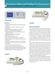
The instrument is a stable and high performance digital multimeter driven<br />
by battery. It uses the LCD with 42mm high make the reading is clearly.<br />
And the function of 20sec. back light and overload protection make<br />
operation is convenient.<br />
The instrument has the function of measuring DCV, ACV, DCA, ACA,<br />
resistance, capacitance, and diode, triode and continuity test. The instrument<br />
takes dual-integral A/D converter as key point, is an excellent tools.<br />
2. SAFETY NOTES<br />
This series meter meets the standard of IEC1010. Read it before operation.<br />
1.Do not input the limited voltage of 1000V DC or 750V AC RMS when<br />
measuring voltage.<br />
2.Voltage less than 36V is safety voltage. When measuring voltage higher<br />
than 36V DC, 25V AC, check the connection, insulation of test leads to<br />
avoid electric shock.<br />
3.When changing function and range, test leads should be removed from<br />
testing point.<br />
4.Select correct function and range.<br />
5.When measuring current, do not input current over 20A.<br />
6.Safety symbols<br />
“ ” exists high voltage,“ ”GND,“ ” dual insulation,“<br />
” must refer to manual,“ ”low battery<br />
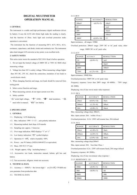
3. SPECIFICATION<br />
1.GENERAL<br />
1-1.Displaying : LCD displaying<br />
1-2.Max. indication: 1999(3 1/2), auto polarity indication<br />
1-3.Measuring method: dual slope A/D transfer<br />
1-4.Sampling rate: approx. 3 times/sec<br />
1-5.Over range indication: MSD displays “1” or“-1”<br />
1-6.Low battery indication: “<br />
” symbol displays<br />
1-7.Operation: 0~40℃,relative humidity
2MΩ<br />
1kΩ<br />
20MΩ<br />
10kΩ<br />
200MΩ ±[5%(rdg –10 )+ 100kΩ<br />
30]<br />
Open voltage: less than 3V<br />
Overload protection: 250V DC or AC peak value<br />
NOTE: a:At 200Ω range, it should make the test leads short to measure<br />
the wire resistance, then, subtracts from the real measurement.<br />
b:At 200 MΩ range, make the test leads short, LCD displays 1.0MΩ,<br />
it’s normal and has no effect on the accuracy and should be subtracted<br />
from real measurement.<br />
2-2-6. CAPACITANCE<br />
RANGE ACCURACY RESOLUTION<br />
20nF ±(2.5%+20) 10pF<br />
200nF<br />
100pF<br />
2uF<br />
1nF<br />
200uF ±(5.0%+10) 100nF<br />
Overload protection: 36V DC or AC peak value<br />
2-2-7. DIODE AND CONTINUITY TEST<br />
RANGE DISPLAYING VALUE TEST CONDITION<br />
Forward voltage Forward DCA is approx.<br />
drop of diode 1mA , backward<br />
voltage is approx. 3V<br />
If the Open voltage is approx.<br />
resistance is less 3V<br />
than 70Ω±20Ω,<br />
buzzer sounds<br />
Overload protection: 250V DC or AC peak value.<br />
Warning: do not input voltage at this range!<br />
2-2-8. TRANSISTOR hFE DATA TEST<br />
RANGE DISPLAYING RANGE TESTING CONDITION<br />
hFE NPN or<br />
PNP<br />
0 ~ 1000 Basic current is approx.<br />
10uA , Vce is<br />
approx. 3V<br />
2-2-9. Live wire identifying<br />
RANGE DISPLAYING ALARM TEST<br />
CONDITION<br />
2-2-10 Logic TTL<br />
RANGE TEST CONDITION RESOLUTION<br />
TTL When Test voltage 0.1V<br />
>2.4V,display“▲”<br />
When Test voltage >0.7V,<br />
SEE THE FIG:<br />
4-2.DCV MEASUREMENT<br />
1.Apply the black test lead to “COM” terminal and the red one to V/Ω/Hz<br />
terminal.<br />
2 . Set the knob to a<br />
proper DCV range, connect the black test lead crossly to the circuit<br />
under tested, the voltage and polarity of the point which the red lead<br />
connect to will display on LCD.<br />
NOTE:<br />
1. If the voltage range is unknown beforehand, set the knob to the highest<br />
range, then, select a proper range according to the displaying value.<br />
2.There is a remained value at small voltage range before measuring, it is<br />
normal and have no effect on measurement. If MSD displays “1”, it<br />
means over range, should set the knob to a higher range.<br />
3.Do not input a voltage over 1000V, or, the circuit might be damaged.<br />
4.Be careful when measuring high voltage circuit.<br />
4-3.ACV MEASUREMENT<br />
1.Apply the black test lead to “COM” terminal and the red one to V/Ω/Hz<br />
terminal.<br />
2.Set the knob to proper ACV range, connect the test leads crossly to the<br />
circuit under tested.<br />
NOTE:<br />
1. If the voltage under tested is unknown beforehand, set the knob to the<br />
highest range, then, select a proper range according to the displaying<br />
value.<br />
2. There is a remained value at small voltage range before measuring, it<br />
is normal and have no effect on measurement. If MSD displays “1” , it<br />
means over range, should set the knob to a higher range.<br />
3.Do not input voltage over 750Vrms,or, the circuit might be damaged.<br />
4.Be careful when measuring high volt circuit.<br />
4-4.DCA MEASUREMENT<br />
1. Apply the black test lead to “COM” terminal, and the red one to mA<br />
terminal (max. 200mA), or red test lead to “20A” terminal ( max.<br />
20A).<br />
2. Set the knob to proper DCA range, connect the meter to the circuit<br />
under tested, the current value and polarity of red test lead connect to<br />
will display on LCD.<br />
NOTE:<br />
3<br />
1. If the current under tested is unknown beforehand, set the knob to the<br />
highest range, then, select proper range according to the displaying<br />
value.<br />
2 . If LCD displays“1”, it means over range, should set the knob to a<br />
higher range.<br />
3. Max. input current is 200mA or 20A(subject to where the rd test lead<br />
apply to ) , too large current will blow the fuse. Be careful at 20A,<br />
because 20A is infused, continuously measuring will make the circuit<br />
heat and effect on the accuracy even damaged the meter.<br />
4-5.ACA MEASUREMENT<br />
1. Apply the black test lead to “COM” terminal and the red one to“mA”<br />
terminal ( max. 200mA ) , or apply the red one to “20A”<br />
terminal(max. 20A).<br />
2. Set the knob to proper ACA range, connect the meter to the circuit<br />
under tested.<br />
NOTE:<br />
1. I f the current under tested is unknown beforehand, set the knob to the<br />
highest range, then, select proper range according to the displaying<br />
value.<br />
2 . If LCD displays“1”, it means over range, should set the knob to a<br />
higher range.<br />
3. Max. input current is 200mA or 20A (subject to where the red test<br />
lead apply to), too large current will blow the fuse. Be careful at 20A,<br />
because 20A is infused, continuously measuring will make the circuit<br />
heat and effect on the accuracy even damaged the meter.<br />
4-6.RESISTANCE MEASUREMENT<br />
1 . Apply the black test lead to “COM” terminal and the red one to<br />
V/Ω/Hz terminal.<br />
2.Set the knob to proper resistance range; connect test leads crossly to the<br />
resistor under tested.<br />
NOTE:<br />
1.If resistance is over selected range value, “1” displays, should set the<br />
knob to a higher range. When measuring value is over 1MΩ, the reading<br />
will take a few seconds to be stable, it’s normal for high resistance<br />
measuring.<br />
2.When input terminal is in open circuit, overload displays.<br />
3.When measuring in line resistor, be sure that power is turned off and all<br />
capacitors are released completely.<br />
4.Do not input any volt at this range.<br />
NOTE: a:At 200Ω range, it should make the test leads short to measure<br />
the wire resistance, then, subtracts from the real measurement.<br />
b:At 200 MΩ range, make the test leads short, LCD displays 1.0MΩ, it’s<br />
normal and has no effect on the accuracy and should be subtracted from<br />
real measurement.<br />
4-7.CAPACITANCE MEASUREMENT
1. Set the knob to proper capacitance range, and insert the test accessory to<br />
“COM” and “mA” terminal. Be aware of that “COM” terminal<br />
corresponds to anode and connects with red test lead, and “mA”<br />
terminal corresponds to cathode and connects with black test lead.<br />
2.Connect test leads to the two points of capacitor, be ware of polarity if<br />
necessary.<br />
NOTE:<br />
1.If the capacitance under tested is over the max. value of selected range,<br />
LCD displays “1” only, thus, should set the knob to a higher range.<br />
2.It’s normal that there is a remained value on LCD before capacitance<br />
measurement, and it has no effect on measuring.<br />
3.When measuring at large capacitance range, if capacitor is broken or<br />
leakage, LCD displays a value and it’s unstable.<br />
4.Release the capacitor completely before measuring.<br />
4-8.TRANSISTOR hFE<br />
1.Set the knob to hFE range. Insert the test accessory to COM and mA<br />
terminal, and the anode is corresponding to COM and cathode is<br />
corresponding to mA terminal.<br />
2. Verify the transistor under tested is NPN or PNP, insert emitter, base<br />
and collector to proper jack.<br />
4-9.DIODE AND CONTINUITY TEST<br />
1.Apply the black test lead to “COM” terminal and the red one to V/Ω/Hz<br />
terminal(the polarity of red lead is “+”).<br />
2 . Set the knob to range, connect test leads to the diode under<br />
tested, the red test lead connects to diode positive polarity, the reading is<br />
the approx. value of diode forward volt drop.<br />
Apply test leads to two points of tested circuit, if the inner buzzer sounds,<br />
the resistance is less than (70±20)Ω.<br />
4-10.DATA HOLD<br />
Press down the key, the present value is held on LCD, press up the key and<br />
the function is cancelled.<br />
4-11.AUTO POWER OFF<br />
After stop working for 20±10 minutes, the meter will be into sleep mode.<br />
Press “POWER” key twice to restart the power.<br />
4-12.BACKLIGHT INDICATION<br />
Press “B/L” key to turn on the backlight, will be auto off after 20 sec.<br />
NOTE: When turning on backlight, the working current will be enlarged; it<br />
will shorten the battery life, and enlarge error on some functions.<br />
4-13. LIVE WIRE VERIFY<br />
1. Remove black test lead from “COM” terminal, insert red lead to<br />
“V/Ω/Hz” terminal.<br />
2. Set the range knob to TEST range, apply red lead to the circuit under<br />
tested.<br />
3. If LCD displays “1”, and alarms with sound and light, it means that<br />
the circuit under tested is live wire; if LCD doesn’t display “1” and doesn’t<br />
alarm, it means the circuit under tested is “0” wire.<br />
4<br />
NOTE:<br />
1. The function is only for testing AC standard live wire (AC 110V~AC<br />
380V).<br />
2. Must be operated under safety rules.<br />
5. MAINTANENCE<br />
Do not try to modify the circuit.<br />
1. Keep the meter away from water, dust and shock.<br />
2. Do not store and operate the meter under the condition of high<br />
temperature, high humidity, combustible, explosive and strong magnetic<br />
place.<br />
3. Wipe the case with a damp cloth and detergent, do not use abrasives and<br />
lcohol.<br />
4. If do not operate for a long time, should take out the battery to avoid<br />
leakage.<br />
4-1. When signal displays, should replace the battery following the<br />
steps:<br />
4-1-1. Unlock the button and remove the battery case.<br />
4-1-2. Take out the old battery and replace the new one. It's better to use<br />
alkaline battery for longer life.<br />
4-1-3. Fit on the battery case and lock the button.<br />
4-2. Fuse replacement<br />
Use the same type fuse as specified.<br />
If the meter does not work properly, check the meter as following:<br />
CONDITIONS<br />
WAY TO SOLVE<br />
NO DISPLAYING ●The power is not turned on<br />
●HOLD key<br />
●replace battery<br />
symbol displays ●replace battery<br />
NO CURRENT ●replace fuse<br />
INPUT<br />
BIG ERROR ●replace battery<br />
●The specifications are subject to change without notice.<br />
●The content of this manual is regarded as correct, error or omits Pls.<br />
contact with factory.<br />
●We hereby will not be responsible for the accident and damage caused<br />
by improper operation.<br />
●The function stated for this User Manual cannot be the reason of<br />
special usage.
MB-9802-50<br />
5