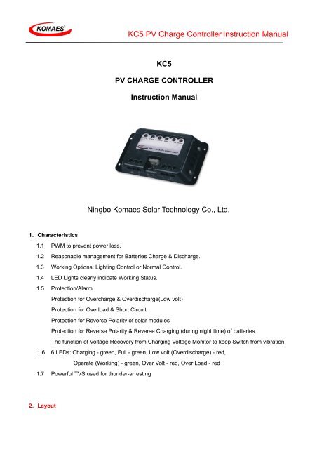
KC5 PV Charge Controller Instruction Manual
KC5 PV Charge Controller Instruction Manual
KC5 PV Charge Controller Instruction Manual

Create successful ePaper yourself
Turn your PDF publications into a flip-book with our unique Google optimized e-Paper software.
<strong>KC5</strong> <strong>PV</strong> <strong>Charge</strong> <strong>Controller</strong> <strong>Instruction</strong> <strong>Manual</strong><strong>KC5</strong><strong>PV</strong> CHARGE CONTROLLER<strong>Instruction</strong> <strong>Manual</strong>Ningbo Komaes Solar Technology Co., Ltd.1.Characteristics1.1 PWM to prevent power loss.1.2 Reasonable management for Batteries <strong>Charge</strong> & Discharge.1.3 Working Options: Lighting Control or Normal Control.1.4 LED Lights clearly indicate Working Status.1.5 Protection/AlarmProtection for Overcharge & Overdischarge(Low volt)Protection for Overload & Short CircuitProtection for Reverse Polarity of solar modulesProtection for Reverse Polarity & Reverse Charging (during night time) of batteriesThe function of Voltage Recovery from Charging Voltage Monitor to keep Switch from vibration1.6 6 LEDs: Charging - green, Full - green, Low volt (Overdischarge) - red,Operate (Working) - green, Over Volt - red, Over Load - red1.7 Powerful TVS used for thunder-arresting2.Layout
<strong>KC5</strong> <strong>PV</strong> <strong>Charge</strong> <strong>Controller</strong> <strong>Instruction</strong> <strong>Manual</strong>6 LEDsCharging FullLowvoltWorkingOvervoltOverload+ - + - + -Module”+”Module”-”Battery”+”FusemodeBattery”-”Loads“+”Loads “-”3.InstallationTerminals from left to right to connect:Anode of modules; cathode of modules; anode of batteries; cathode of batteries; anode of loads;cathode of loads.Cable selection according to Current of Loads;Selected cables to connect batteries are better shorter& thicker to prevent power loss.Note: <strong>KC5</strong> is designed for lead-acid battery, it may affect if use other types.Installation & Notices1 Enough room is needed for heat elimination.Installation & operation Temperature: -20℃~+50℃.2 Terminal is set in the back of <strong>KC5</strong> (Metal backing) for thunder-arresting by TVS when wellgrounded.3 Shall connect orderly as: a. Batteries b. Modules c. Loads.Note: Singlechip of <strong>KC5</strong> is powered by Batteries, so need connect to the Battery first.Attention to Anode & Cathode with connection.Metal backing Must be well grounded.45Temperature Sensor is fixed in <strong>KC5</strong> with down-lead.Temperature Sensor can be moved and fixed on batteries by down-lead if too much Temperaturedifference between <strong>KC5</strong> and Batteries.Rated Voltage of batteries needs to match Working Voltage of modules.4.Functions
4.1 Electro-management2 Control modes are optional:●●Lighting Mode (Default Mode)<strong>KC5</strong> <strong>PV</strong> <strong>Charge</strong> <strong>Controller</strong> <strong>Instruction</strong> <strong>Manual</strong>Under this mode, if the voltage reaches the one that Lighting Mode requires when Light getslower enough, and <strong>KC5</strong> will automatically switch on the loads after 3 minutes time delayNormal ModeUnder this mode, users need to turn on/off the loads manually.The Loads will keep being charged unless Protection Status is activated.See details in 5.4.2 Battery Charging ManagementManagement proceeds Precharge, Voltage Limit, Float <strong>Charge</strong> according to different InitialStatus of BatteriesPre-charge works after deep Discharge, in case of a shock to the batteries from initial impactcurrent.Efficient PWM begins to charge after a certain charge from the battery, and turns to Voltage Limit<strong>Charge</strong> when goes into the limited line.Float charge begins and keeps its status at the end of the process. “Full” LED turns on.Float charge will keep working to recover the loss from self-discharge of the batteries.Battery Temperature Compensation is functional at this same timeVoltage Valve’s Value of each reference point to be recovered by this function.Batteries’ Valves’ Values falls down when temperature gets up.Too high charging voltage will lead harmful gas and water missing of the batteries whentemperature gets too high.And it will be undercharge to the batteries when too low temperature.Temperature Compensation will automatically adjust the Charging Voltage at that moment.The range of Temperature Compensation is -20℃--50 ℃ , it is not available when out of thisrange.It keeps Final Charging Voltage never exceeds to the one required.Efficient PWM mode keeps batteries working at the best status, which much extends their lives.4.3 Working Indication6 LEDs for indications1 Charging, green LED: Charging, charging current exists2 Full, green LED: Fully <strong>Charge</strong>d3 Low volt, red LED: Flashing for Alarm, keep red for protection’s activated.
<strong>KC5</strong> <strong>PV</strong> <strong>Charge</strong> <strong>Controller</strong> <strong>Instruction</strong> <strong>Manual</strong>4 Operate, green LED: Working normally5 Over volt, red LED: Flashing for Alarm, keep red for protection’s activated.6 Over Load, red LED: Fuse blows out when output current bigger than rated current.4.4 Protection& Alarm● Overcharge Protection<strong>KC5</strong> controls pv modules when the Charging Voltage of the batteries gets to the biggest butallowable one, it keeps batteries safe from too high charging voltage.● Overdischarge (Low volt) Protection“Low volt” flashes when the batteries’ voltage is too low, it will stop flashing to turn to red ifvoltage keeps down to the Protection Line, and loads will be disconnected at this same time tokeep batteries safe from Overdischarge. Protection stops when batteries enough charged, and“Low volt” LED turns off.● Overvoltage Protection“Over volt” flashes when Terminal Voltage exceeds the one required, it will stop flashing to turn tored if voltage keeps up to the Protection Line. And loads will be automatically disconnected at thissame time to keep loads safe from Overvoltage.Protection stops when batteries get back to normal voltage, and “Over volt” LED turns off.● Batteries Reverse Polarity ProtectionFuse blows to protect batteries when Reverse Polarity of batteries.It can be back to work after user corrects the connections and renews the fuse.● Modules Reverse Polarity ProtectionModules can be back to work after connections corrected.● Overload ProtectionFuse blows and “Over Load” LED turns on when total current exceeds the rated one.It recovers and back to work after fuse renewed.5.Operation instructionsNormal control and Lighting Control are 2 modes for selection.Loads are powered under Normal Mode, unless Low Voltage or Over VoltageLoads are powered under Lighting Mode, unless low voltage or over voltage, or the Modules’ voltageis too low.6.Warranty & After Service
<strong>KC5</strong> <strong>PV</strong> <strong>Charge</strong> <strong>Controller</strong> <strong>Instruction</strong> <strong>Manual</strong>One year warranty.Guarantee is not working if the Damage caused by shipping, improper operation or any otherman-made behavior.Professional lightning protection is additionally needed if <strong>KC5</strong> used under where lightning oftenhappens, and no guarantee is available in this case.Note: TVS lightning protection is the last necessary protection only.7.Malfunction & Troubleshooting:Malfunction“Charging” not available butsun shines“Over volt” turns on, no output“Low volt” turns on, no output“Over Load” turns on, nooutputTroubleshootingCheck the connections of modules, see if any reverseconnections.Check the batteries, see if any wrong with fuseconnectionIt will automatically back to work. When batteries areenough charged,Over Load protection or short circuit protectionactivated, need to renew fuse after protection.8. Parameters sheetTechnical ParametersNominal System VoltageMax. <strong>PV</strong> Charging CurrentNon-load Current<strong>KC5</strong>DC12V / 24V20A≤60mARegulation Voltage ≤ 14.4V / 28.8VFloat Voltage 14.1V / 28.2VRated Load CurrentOverload, Short CircuitProtection20AFuse blowouts when over Rated CurrentLow Voltage Alarm ≤ 11.4V / 22.8V
Low Voltage Disconnect(Protection Voltage)Low Voltage DisconnectRecovery Voltage<strong>KC5</strong> <strong>PV</strong> <strong>Charge</strong> <strong>Controller</strong> <strong>Instruction</strong> <strong>Manual</strong>≤ 10.8V / 21.6V≥ 13.4V / 24.6VOvervoltage Alarm ≥ 15.0V / 30.0VOvervoltage Protection ≥ 15.5V / 31.0VOvervoltage Recovery ≤ 14.4V / 28.8VWorking Temperature.Temperature CompensationOver TemperatureProtectionOver TemperatureRecovery-20℃~+50℃-3.9mV/℃≥75℃≤65℃