P0689 EN VPA-D Progressive distributor - TROMA-MACH sro
P0689 EN VPA-D Progressive distributor - TROMA-MACH sro
P0689 EN VPA-D Progressive distributor - TROMA-MACH sro

Create successful ePaper yourself
Turn your PDF publications into a flip-book with our unique Google optimized e-Paper software.
4<br />
Bypass line<br />
5<br />
6<br />
4<br />
5<br />
6<br />
4<br />
5<br />
6<br />
4<br />
5<br />
6<br />
left-side<br />
Main line<br />
I<br />
II<br />
III<br />
I<br />
II<br />
III<br />
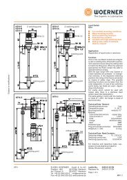
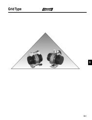
Fig. 1<br />
Bypass line<br />
Fig. 2<br />
Fig. 3<br />
Fig. 4<br />
right-side<br />
1<br />
2<br />
3<br />
1<br />
2<br />
3<br />
1<br />
2<br />
3<br />
1<br />
2<br />
3<br />
Functional process fig. 1 ... 4:<br />
The lubricant flows from the main line<br />
through the right-side ring groove of piston<br />
III as well as the bypass line (right) and to<br />
the left side of piston I and moves it into its<br />
home position. The lubricant displaced by<br />
piston I is ejected via the left bypass line<br />
through outlet no. 6.<br />
After shifting of piston I, lubricant flows to<br />
the left side of piston II and pushes it into its<br />
right-side home position. The displaced<br />
lubricant is ejected via outlet no. 1.<br />
After shifting of piston II, lubricant flows to<br />
the left side of piston III and pushes it into its<br />
right-side home position. The displaced<br />
lubricant is ejected via outlet no. 2.<br />
After shifting of piston III, lubricant flows to<br />
the right side of piston I and pushes it into its<br />
left-side home position. The displaced<br />
lubricant is ejected via outlet no. 3. The<br />
continuation of that process is evidenced in<br />
the scheme depicted.<br />
EUG<strong>EN</strong> WOERNER GmbH & Co. KG<br />
Postfach 1661 DE-97866 Wertheim<br />
Am Eichamt 8 DE-97877 Wertheim<br />
Tel. +49 (0) 9342 803-0 info@woerner.de<br />
Fax.+49 (0) 9342 803-202 www.woerner.de<br />
Monitoring of<br />
progressive <strong>distributor</strong>s:<br />
As for instance due to soiling, the flow<br />
through a lubricant point line may be<br />
prevented. This will cause a piston to get<br />
blocked. By virtue of the forced control as<br />
depicted in figures 1 up to 4, the other<br />
pistons will be stopped as well.<br />
Due to this configuration, the proportioning<br />
at all outlets of the <strong>distributor</strong> can be<br />
monitored by means of a sensor at one<br />
piston only.<br />
Mounting note:<br />
The pistons are provided with an extremely<br />
small fitting clearance. Therefore, the<br />
pistons, after the dismantling of a<br />
<strong>distributor</strong>, must never be interchanged.<br />
Formula for calculating the lubricant<br />
available per lubrication point<br />
A progressive <strong>distributor</strong> allocates the<br />
delivered lubricant to the individual lubrication<br />
points in forced order. Due to the<br />
functional process as described herein, a<br />
safe proportioning is ensured.<br />
The lubricant qi delivered to a lubrication<br />
point i can be calculated as follows<br />
Ki q i = �������� � Q<br />
2 � (K 1+K 2+K 3...)<br />
Q = lubricant delivered to the<br />
<strong>distributor</strong>,<br />
K = distinctive number of the outlet i<br />
i<br />
Leaflet-No. 0689 <strong>EN</strong><br />
Page 6 of 6<br />
- Subject to modifications -