P0689 EN VPA-D Progressive distributor - TROMA-MACH sro
P0689 EN VPA-D Progressive distributor - TROMA-MACH sro
P0689 EN VPA-D Progressive distributor - TROMA-MACH sro

Create successful ePaper yourself
Turn your PDF publications into a flip-book with our unique Google optimized e-Paper software.
- Subject to modifications -<br />
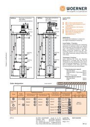
A = Mounting point at <strong>distributor</strong> (for<br />
viewing indicator and electrical functionality<br />
check)<br />
B = Mounting point for viewing indicator<br />
at <strong>distributor</strong> (if point A is occupied)<br />
D = DPA-D proportioning block<br />
H = Main line<br />
K = Proportioning volume distinctive<br />
number<br />
M = 2 M8 fastening threads for mounting<br />
of auxiliary units (for example, see<br />
data sheet 0684)<br />
R = APA-D connecting plate<br />
S = Mid fastening screw<br />
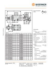
<strong>Progressive</strong> <strong>distributor</strong> <strong>VPA</strong>-D<br />
205.600<br />
Number<br />
of outlets<br />
6<br />
8<br />
10<br />
12<br />
14<br />
16<br />
18<br />
20<br />
Length<br />
"a"<br />
Length<br />
"s"<br />
Weight<br />
[kg]<br />
166 - 3,00<br />
199 - 3,70<br />
232 - 4,40<br />
270 116 5,10<br />
303 149 5,80<br />
340 149 6,50<br />
373 182 7,20<br />
406 182 7,90<br />
EUG<strong>EN</strong> WOERNER GmbH & Co. KG<br />
Postfach 1661 DE-97866 Wertheim<br />
Am Eichamt 8 DE-97877 Wertheim<br />
Tel. +49 (0) 9342 803-0 info@woerner.de<br />
Fax.+49 (0) 9342 803-202 www.woerner.de<br />
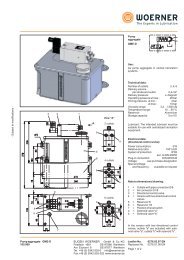
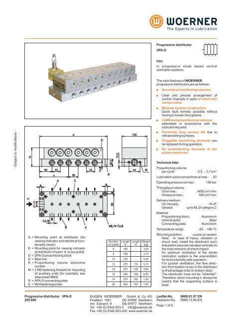
<strong>Progressive</strong> <strong>distributor</strong><br />
<strong>VPA</strong>-D<br />
Use:<br />
In progressive mode based central<br />
lubrication systems.<br />
The main features of WOERNER<br />
progressive <strong>distributor</strong>s are as follows:<br />
�<br />
�<br />
�<br />
�<br />
�<br />
�<br />
Accurate proportioning volumes.<br />
Clear and precise arrangement of<br />
control channels in spite of small-size<br />
construction.<br />
Modular system construction.<br />
Quick fault remedy possible without<br />
having to loosen the pipeline.<br />
4 different proportioning volumes<br />
selectable in accordance with the<br />
lubricant required.<br />
Extremely long service life<br />
refined sliding surfaces.<br />
Leaflet-No. 0689.01.07 <strong>EN</strong><br />
Replaces No. 0689.12.06 <strong>EN</strong><br />
Page 1 of 6<br />
due to<br />
Pluggable monitoring elements can<br />
be replaced during operation.<br />
� No proportioning decrease at the<br />
piston monitored.<br />
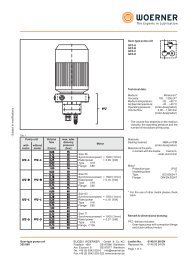
Technical data:<br />
Proportioning volume<br />
per cycle:<br />
0,9 ... 3,7 cm³<br />
Lubrication point connections at max.: 20<br />
Operating pressure at max.: 150 bar<br />
Throughput volume:<br />
Oil at max.: 6000 cm³/min<br />
Grease at max.: 600 cm³/min<br />
Delivery medium:<br />
Oil viscosity:<br />
>6 cP<br />
Grease:<br />
up to NLGI category 2<br />
Material:<br />
Proportioning block:<br />
Aluminium<br />
Internal parts:<br />
Steel<br />
Connecting plate:<br />
Aluminium<br />
Temperature range:<br />
-20 ... +80 °C<br />
Mounting position:<br />
usually as needed<br />
Note: In case of heavy vibration or<br />
shock load, install the <strong>distributor</strong> such<br />
that piston axes are situated vertically to<br />
the main direction of shock impact.<br />
An optimum ventilation of the whole<br />
lubrication system is the precondition<br />
for its functionally safe operation.<br />
For quicker ventilation, the flow direction<br />
from bottom to top in the <strong>distributor</strong><br />
is of advantage (inlet on bottom side).<br />
The <strong>distributor</strong> must not be "distorted".<br />
Therefore, when mounting it, always be<br />
careful that the supporting surface is<br />
level.
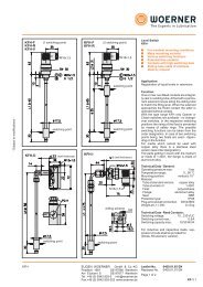
Visual check<br />
Casing for initiator<br />
Choice of initiators:<br />
Designation /<br />
Purchase-no.<br />
Suits for<br />
Dimension<br />
drawing:<br />
Connection<br />
diagram:<br />
Operating voltage:<br />
Initiator "C"<br />
913.900-03<br />
Casing "W"<br />
Switching distance�5mm<br />
Initiator "F"<br />
913.900-11<br />
Casing "D" und "W"<br />
Switching distance�8mm<br />
Initiator "N"<br />
913.900-21<br />
Casing "D" und "W"<br />
Switching distance�8mm<br />
Functional checks:<br />
Visual check:<br />
In a translucent polyamide casing, a red pin<br />
being fixed to the piston shows the piston's<br />
movement.<br />
Casing material: Polyamide, translucent<br />
Ambient temperature: -10 ... +80 °C<br />
Weight: 0,35 kg<br />
Mounting point at <strong>distributor</strong>: Aor B<br />
Electrical check with initiator:<br />
Casing for initiator:<br />
A pin being connected with the piston<br />
attenuates an initiator once per cycle.<br />
Version "D":<br />
Casing material: Polyamide, translucent<br />
(Piston movement is visible)<br />
for initiators with a<br />
switching distance of: �8<br />
mm<br />
Version "W":<br />
Casing material: Polyamide, black<br />
for initiators with a<br />
switching distance of: �5<br />
mm<br />
Use initiator with M18x1 thread!<br />
(When using other initiators than those<br />
depicted below, such initiators must be<br />
checked for suitability.)<br />
Initiator "I"<br />
913.900-14<br />
Casing "W"<br />
Switching distance�5mm<br />
Leaflet-No. 0689 <strong>EN</strong><br />
Page 2 of 6<br />
Initiator "2"<br />
979.044-88<br />
Casing "W"<br />
�5mm<br />
10 ... 30 VDC 20 ... 250 VUC 10 ... 30 VDC 10 ... 30 VDC 10 ... 30 VDC<br />
Residual ripple: � 10% � 15%<br />
� 15% � 15%<br />
Load current at max.: 250 mA 500 mA 130 mA<br />
200 mA 130 mA<br />
Protection system: IP67 IP67 IP67<br />
IP67 IP67<br />
Power connection: Cable 3 m Cable 3 m Unit plug (see accessories page 3)<br />
Switching distance<br />
Length "A": 60 mm 62 mm 45 mm<br />
83 mm 65 mm<br />
EUG<strong>EN</strong> WOERNER GmbH & Co. KG<br />
Postfach 1661 DE-97866 Wertheim<br />
Am Eichamt 8 DE-97877 Wertheim<br />
Tel. +49 (0) 9342 803-0 info@woerner.de<br />
Fax.+49 (0) 9342 803-202 www.woerner.de<br />
- Subject to modifications -
- Subject to modifications -<br />
Version "R"<br />
Version "RK"<br />
Version "RS"<br />
Accessories:<br />
Cable jack for functionality check "RS" and initiator<br />
(state purchase-no., please)<br />
Cable jack with LED and cable Cable jack with terminal clamps<br />
LED yellow = function display<br />
green = operating voltage<br />
EUG<strong>EN</strong> WOERNER GmbH & Co. KG<br />
Postfach 1661 DE-97866 Wertheim<br />
Am Eichamt 8 DE-97877 Wertheim<br />
Tel. +49 (0) 9342 803-0 info@woerner.de<br />
Fax.+49 (0) 9342 803-202 www.woerner.de<br />
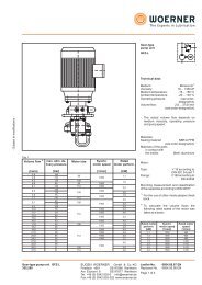
Electrical check with<br />
reed contact:<br />
A magnet connected with the piston<br />
switches the reed contact once per cycle.<br />
Switching voltage: 10 ... 36 VUC<br />
Switching current at max.: 25 mA<br />
Switching power at max.: 0,9 VA<br />
Ambient temperature: -5 ... +80 °C<br />
Mounting point at <strong>distributor</strong>: A<br />
Version "R"<br />
with DIN 43650Aplug-in connection:<br />
Material (casing): Al or. 1.4305<br />
System of protection: IP65<br />
Connection<br />
diagram:<br />
Version "RK"<br />
with cable:<br />
Material (casing): PA or 1.4305<br />
System of protection: IP65<br />
Cable<br />
Length: 10 m<br />
Cross section: 2x0,75 mm²<br />
Material: Oelflex<br />
Connection<br />
diagram:<br />
Version "RS"<br />
with unit<br />
plug, 4-pin (M12):<br />
(for matching cable jack see accessories)<br />
Material (casing): PA or 1.4305<br />
Connection<br />
diagram:<br />
Cable jack with LED and cable:<br />
Purchase-no.:<br />
913.404-19<br />
Operating voltage:<br />
Cable<br />
10 ... 30 VDC<br />
Cross section: 3x0,34 mm²<br />
Length: 5 m<br />
System of protection: IP68<br />
Cable jack with terminal clamps:<br />
(without LED)<br />
Purchase-no.:<br />
913.404-24<br />
Connection type: Screws<br />
Connection cross section: max. 0,75 mm²<br />
Cable diameter: 4 ... 6 mm<br />
System of protection: IP67<br />
Leaflet-No. 0689 <strong>EN</strong><br />
Page 3 of 6
Purchase-designation:<br />
<strong>Progressive</strong> <strong>distributor</strong><br />
Number<br />
of outlets<br />
6 ... 20<br />
increasing by<br />
2 outlets<br />
each<br />
Functionality<br />
check<br />
viewing<br />
indicator<br />
with S<br />
without<br />
without<br />
Reed<br />
contact<br />
Purchase-designation: Proportioning block<br />
Purchase-designation: Connecting plate<br />
Distributor view Scheme<br />
0<br />
Electrical<br />
checking device<br />
mounted at<br />
1st<br />
place 1)<br />
last<br />
place 2)<br />
0<br />
Z<br />
<strong>VPA</strong>-D<br />
Electrical check Initiator<br />
Translucent D<br />
initiator casing<br />
Switching distance�8mm<br />
Reinforced W<br />
initiator casing<br />
Switching distance�5mm<br />
DPA-D<br />
APA-D<br />
without<br />
N F<br />
N I 2<br />
C F<br />
EUG<strong>EN</strong> WOERNER GmbH & Co. KG<br />
Postfach 1661 DE-97866 Wertheim<br />
Am Eichamt 8 DE-97877 Wertheim<br />
Tel. +49 (0) 9342 803-0 info@woerner.de<br />
Fax.+49 (0) 9342 803-202 www.woerner.de<br />
Proportioning volume per<br />
piston stroke and outlet<br />
[cm³] distinctive no.<br />
0,9<br />
1,8<br />
2,7<br />
3,7<br />
09<br />
18<br />
27<br />
37<br />
Purchase-example:<br />
(for the <strong>distributor</strong> as depicted here)<br />
<strong>Progressive</strong> <strong>distributor</strong> with 12 outlets,<br />
without visual check "0", with receptacle for<br />
initiator "W" with initiator "C", proportioning<br />
distinctive numbers "37", "18", "18", "27",<br />
"37", "09", gasket material "P".<br />
Purchase-designation:<br />
<strong>VPA</strong>-D / 12 / 0 / W / C / 37 / 18 / 18 / 27 /<br />
37 / 09 / P<br />
R : P P A V 0 0<br />
M : K K Z K Z Z<br />
L : B B 0 0 B A<br />
Leaflet-No. 0689 <strong>EN</strong><br />
Page 4 of 6<br />
Gasket material<br />
NBR<br />
(Perbunane)<br />
FPM<br />
(Viton)<br />
- Subject to modifications -
- Subject to modifications -<br />
Combination of outlets,<br />
doubling the proportioning volume at an outlet:<br />
Connect opposing outlets by removing the "Z" screw.<br />
Close the not needed outlet with the lock screw.<br />
Without removal of the "Z" screw, no outlet must be locked.<br />
Add-on elements and combination of outlets:<br />
Distinctive letters:<br />
B = double bridge<br />
P = triple bridge<br />
A = Outlet<br />
at the bridge<br />
Z = opposing outlets separated<br />
K = opposing outlets connected<br />
0 = open outlet<br />
V = Lock<br />
screw<br />
Accessories:<br />
Pipe screw fittings DIN 2363: (please state purchase-no.)<br />
Connection<br />
thread<br />
5 outlets are combined into one outlet<br />
by means of a triple bridge, a double<br />
bridge, and removal of the "Z" screws.<br />
2 opposing outlets are combined by<br />
removing the "Z" screws.<br />
Pipe screw fitting with pipe outer diameter Check valve with pipe outer diameter<br />
8 10 12 15 18 10 12 15<br />
G3/8 951.100-13 951.100-15 951.100-16 951.100-25 951.100-24 - 952.800-04 -<br />
G1/2 - 951.101-34 951.100-72 951.100-18 951.100-19 - - -<br />
Bridges and lock screw: (please state purchase-no.)<br />
double without<br />
outlet (B-B)<br />
triple without<br />
outlet (P-P-P)<br />
Bridges<br />
double with<br />
outlet (B-A)<br />
triple with<br />
outlet (P-P-A)<br />
double without<br />
outlet (B-B)<br />
Bridges (location of the mid fastening screw "S")<br />
triple without<br />
outlet (P-P-P)<br />
double with<br />
outlet (B-A)<br />
205.645-65 205.635-65 205.690-65 205.695-65 205.643-65 205.634-65 205.692-65 205.692-65 205.688-65<br />
Mid fastening screw position "S"<br />
EUG<strong>EN</strong> WOERNER GmbH & Co. KG<br />
Postfach 1661 DE-97866 Wertheim<br />
Am Eichamt 8 DE-97877 Wertheim<br />
Tel. +49 (0) 9342 803-0 info@woerner.de<br />
Fax.+49 (0) 9342 803-202 www.woerner.de<br />
Open outlets<br />
2 adjacent outlets are combined into<br />
one outlet by means of a double<br />
bridge.<br />
Leaflet-No. 0689 <strong>EN</strong><br />
Page 5 of 6<br />
triple with<br />
outlet (P-P-A)<br />
Z<br />
Lock screw<br />
"V"
4<br />
Bypass line<br />
5<br />
6<br />
4<br />
5<br />
6<br />
4<br />
5<br />
6<br />
4<br />
5<br />
6<br />
left-side<br />
Main line<br />
I<br />
II<br />
III<br />
I<br />
II<br />
III<br />
Fig. 1<br />
Bypass line<br />
Fig. 2<br />
Fig. 3<br />
Fig. 4<br />
right-side<br />
1<br />
2<br />
3<br />
1<br />
2<br />
3<br />
1<br />
2<br />
3<br />
1<br />
2<br />
3<br />
Functional process fig. 1 ... 4:<br />
The lubricant flows from the main line<br />
through the right-side ring groove of piston<br />
III as well as the bypass line (right) and to<br />
the left side of piston I and moves it into its<br />
home position. The lubricant displaced by<br />
piston I is ejected via the left bypass line<br />
through outlet no. 6.<br />
After shifting of piston I, lubricant flows to<br />
the left side of piston II and pushes it into its<br />
right-side home position. The displaced<br />
lubricant is ejected via outlet no. 1.<br />
After shifting of piston II, lubricant flows to<br />
the left side of piston III and pushes it into its<br />
right-side home position. The displaced<br />
lubricant is ejected via outlet no. 2.<br />
After shifting of piston III, lubricant flows to<br />
the right side of piston I and pushes it into its<br />
left-side home position. The displaced<br />
lubricant is ejected via outlet no. 3. The<br />
continuation of that process is evidenced in<br />
the scheme depicted.<br />
EUG<strong>EN</strong> WOERNER GmbH & Co. KG<br />
Postfach 1661 DE-97866 Wertheim<br />
Am Eichamt 8 DE-97877 Wertheim<br />
Tel. +49 (0) 9342 803-0 info@woerner.de<br />
Fax.+49 (0) 9342 803-202 www.woerner.de<br />
Monitoring of<br />
progressive <strong>distributor</strong>s:<br />
As for instance due to soiling, the flow<br />
through a lubricant point line may be<br />
prevented. This will cause a piston to get<br />
blocked. By virtue of the forced control as<br />
depicted in figures 1 up to 4, the other<br />
pistons will be stopped as well.<br />
Due to this configuration, the proportioning<br />
at all outlets of the <strong>distributor</strong> can be<br />
monitored by means of a sensor at one<br />
piston only.<br />
Mounting note:<br />
The pistons are provided with an extremely<br />
small fitting clearance. Therefore, the<br />
pistons, after the dismantling of a<br />
<strong>distributor</strong>, must never be interchanged.<br />
Formula for calculating the lubricant<br />
available per lubrication point<br />
A progressive <strong>distributor</strong> allocates the<br />
delivered lubricant to the individual lubrication<br />
points in forced order. Due to the<br />
functional process as described herein, a<br />
safe proportioning is ensured.<br />
The lubricant qi delivered to a lubrication<br />
point i can be calculated as follows<br />
Ki q i = �������� � Q<br />
2 � (K 1+K 2+K 3...)<br />
Q = lubricant delivered to the<br />
<strong>distributor</strong>,<br />
K = distinctive number of the outlet i<br />
i<br />
Leaflet-No. 0689 <strong>EN</strong><br />
Page 6 of 6<br />
- Subject to modifications -