ROSTA RUBBER SUSPENSION UNITS
ROSTA RUBBER SUSPENSION UNITS
ROSTA RUBBER SUSPENSION UNITS

You also want an ePaper? Increase the reach of your titles
YUMPU automatically turns print PDFs into web optimized ePapers that Google loves.
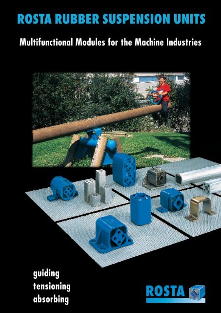
<strong>ROSTA</strong> <strong>RUBBER</strong> <strong>SUSPENSION</strong> <strong>UNITS</strong><br />
Multifunctional Modules for the Machine Industries<br />
guiding<br />
tensioning<br />
absorbing<br />
<strong>ROSTA</strong>
<strong>ROSTA</strong><br />
Product Range “Modules”<br />
<strong>ROSTA</strong> Rubber Suspension Unit<br />
Type DR-S Page 19<br />
Rubber Suspension Units<br />
Housing made out of steel, inner square section made out<br />
of steel tube for mounting “plug-in” lever arms on one or<br />
both sides. The inserted part should be at least three times<br />
longer than the clearance “C”. Up to type DR-S 18 the lever<br />
arms can be mounted by one through-bolt and the levers<br />
are then fixed by frictional force at any position within<br />
360°. Both ways of fixation are particularly well suited for<br />
motions at the plus or minus angular range (no alternating<br />
motions across the neutral axis = play). All metal parts are<br />
paint-finished.<br />
<strong>ROSTA</strong> Rubber Suspension Unit<br />
Type DR-A/C Pages 20/21<br />
Steel housing with inner square section made of light alloy<br />
with four small bores or one big through bore. Levers can<br />
be mounted on one or on both sides by means of bolts.<br />
Type DR-A with two or four through bores, especially constructed<br />
for transmitting alternating motions by passing the<br />
neutral axis in either direction. Type DR-C with central<br />
bore. The frictional force of this type assures a safe fixation<br />
of the lever arms in any position. All metal parts are paintfinished.<br />
<strong>ROSTA</strong> Rubber Suspension Unit<br />
Type DK-S Page 22<br />
Round housing made of light alloy profile, inner square<br />
section made out of steel tube, the “plug-in” lever arms can<br />
be mounted on one or both sides. The inserted part should<br />
be at least three times longer than the clearance “C”. This<br />
kind of connection is particularly well suited for angular<br />
motions at the plus or minus range (no alternating motions<br />
across the neutral axis = play). All metal parts are paintfinished.<br />
<strong>ROSTA</strong> Rubber Suspension Unit<br />
Type DK-A Page 23<br />
Round housing and inner square section made of light<br />
alloy profiles, inner square section with four “throughbores”,<br />
the lever arms can be bolted on and, if necessary,<br />
the bores can be tapped, too. Both ways provide an excellent<br />
connection without play which is necessary in order to<br />
transmit alternating motions by passing the neutral position<br />
in either direction. All metal parts are paint-finished.<br />
16
<strong>ROSTA</strong><br />
Product Range<br />
<strong>ROSTA</strong> Rubber Suspension Unit<br />
Type DO-S Page 24<br />
Housing up to size 45 made out of light alloy profile, size 50<br />
made out of spheroidal graphite cast iron, inner square<br />
section made out of steel, the “plug-in” lever arms are to<br />
be attached on one or both sides. Please note, the inserted<br />
length should be at least three times longer than the clearance<br />
“C”. Up to size DO-S 18 the lever arms can also be<br />
mounted by one “through-bolt”, the levers are held by the<br />
resulting frictional force. Thereby, the positioning of the<br />
levers at any position within 360° is admissible. Both ways<br />
are particularly well suited for alternating motions at the<br />
plus or minus angular range. All metal parts are paintfinished.<br />
Rubber Suspension Units<br />
<strong>ROSTA</strong> Rubber Suspension Unit<br />
Type DO-A Page 25<br />
Housing up to size 45 made out of light alloy profile, size 50<br />
made out of spheroidal graphite cast iron, inner square<br />
section made out of light alloy profile with four “throughbores”.<br />
The levers can be mounted on one or both sides by<br />
means of bolts. It provides an excellent attachment without<br />
play which is most important in order to transmit alternating<br />
motions by passing the neutral axis in either direction.<br />
All metal parts are paint-finished.<br />
<strong>ROSTA</strong> Rubber Suspension Unit<br />
Type DW-A Page 26<br />
Housing with welded-on brackets and inner square section<br />
made out of steel, inner square section with four threaded<br />
holes on both sides, suitable for mounting lever arms and<br />
attachments clearance-free. The unit has to be bolted on<br />
machine part through the welded-on brackets. These units<br />
are designed to transmit alternating motions which occur in<br />
either direction, by passing the neutral position. All metal<br />
parts are paint-finished.<br />
17
<strong>ROSTA</strong><br />
Product Range<br />
<strong>ROSTA</strong> modules should be connected on machine<br />
parts/structures by means of the standardized<br />
clamps and brackets. Relevant welded connections<br />
would affect (overheat) the rubber inserts<br />
and damage the entire suspension device!<br />
Rubber Suspension Units<br />
<strong>ROSTA</strong> Clamp Type BR Page 27<br />
(fitting all DR-elements)<br />
The clamps are supplied separately without bolts. They are<br />
standardized to fit exactly for the fixation and positioning<br />
of the <strong>ROSTA</strong> rubber suspension units type DR-S, DR-A and<br />
DR-C without any welding. For longer units two or more<br />
clamps are recommended. The clamps are paint-finished.<br />
<strong>ROSTA</strong> Clamp Type BK Page 27<br />
(fitting all DK-elements)<br />
The clamps are supplied separately without bolts. They are<br />
standardized to fit exactly for the fixation and positioning<br />
of the <strong>ROSTA</strong> rubber suspension units type DK-S and DK-A<br />
by frictional force created by the bolted double clamp. For<br />
longer units two or more clamps are recommended. All<br />
clamps are paint-finished.<br />
<strong>ROSTA</strong> Bracket Type WS Page 27<br />
This multi-purpose brackets make an easy screw connection<br />
possible on the inner squares of the <strong>ROSTA</strong> rubber<br />
suspension units type DR-A, DK-A and DO-A (as well as a<br />
housing fixation of the tensioner devices type SE). The base<br />
of the angle section can be positioned in both directions<br />
and offers together with the different clamps many combination<br />
possibilities of the element assembling. The brackets<br />
are paint-finished.<br />
18
<strong>ROSTA</strong><br />
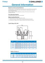
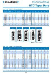
Rubber Suspension Unit<br />
Type DR-S<br />
Torque M in Nm at ) <br />
Weight<br />
Art. No. Type L L1 0<br />
– 0.3 C* D** S 5° 10° 15° 20° 25° 30° in kg<br />
01 021 001 DR-S 11 x 20 20 25 8 + 0.25<br />
0 20 +0.1<br />
– 0.2 11 0.3 0.8 1.3 2.0 2.9 4.0 0.04<br />
01 021 002 DR-S 11 x 30 30 35 8 + 0.25<br />
0 20 +0.1<br />
– 0.2 11 0.4 1.2 2.0 3.1 4.3 6.0 0.05<br />
01 021 003 DR-S 11 x 50 50 55 8 + 0.25<br />
0 20 +0.1<br />
– 0.2 11 0.7 2.0 3.4 5.1 7.2 10.0 0.08<br />
Rubber Suspension Units<br />
01 021 004 DR-S 15 x 25 25 30 11 + 0 0.25<br />
27 +0.2<br />
– 0.1 15 0.7 1.6 2.6 4.0 5.7 8.2 0.07<br />
01 021 005 DR-S 15 x 40 40 45 11 + 0 0.25<br />
27 +0.2<br />
– 0.1 15 1.1 2.5 4.2 6.4 9.2 13.2 0.12<br />
01 021 006 DR-S 15 x 60 60 65 11 + 0 0.25<br />
27 +0.2<br />
– 0.1 15 1.6 3.8 6.3 9.6 13.8 19.8 0.18<br />
01 021 007 DR-S 18 x 30 30 35 12 + 0.25<br />
0 32 +0.1<br />
– 0.2 18 1.9 4.5 7.5 11.0 15.0 20.6 0.12<br />
01 021 008 DR-S 18 x 50 50 55 12 + 0.25<br />
0 32 +0.1<br />
– 0.2 18 3.2 7.5 12.5 18.3 25.0 34.4 0.20<br />
01 021 009 DR-S 18 x 80 80 85 12 + 0.25<br />
0 32 +0.1<br />
– 0.2 18 5.1 12.0 20.0 29.3 40.0 55.0 0.32<br />
01 021 010 DR-S 27 x 40 40 45 22 + 0.25<br />
0 45 +0.2<br />
– 0.1 27 4.7 10.7 17.5 26.9 39.5 57.0 0.26<br />
01 021 011 DR-S 27 x 60 60 65 22 + 0.25<br />
0 45 +0.2<br />
– 0.1 27 7.0 16.0 26.3 40.3 59.3 85.5 0.39<br />
01 021 012 DR-S 27 x 100 100 105 22 + 0.25<br />
0 45 +0.2<br />
– 0.1 27 11.7 26.7 43.8 67.2 98.8 142.5 0.65<br />
01 021 013 DR-S 38 x 60 60 70 30 + 0 0.25<br />
60 + – 0.15<br />
0.3 38 13.0 30.4 50.6 78.0 113.0 162.0 0.67<br />
01 021 014 DR-S 38 x 80 80 90 30 + 0 0.25<br />
60 + – 0.15<br />
0.3 38 17.3 40.5 67.5 104.0 151.0 216.0 0.90<br />
01 021 015 DR-S 38 x 120 120 130 30 + 0 0.25<br />
60 + – 0.15<br />
0.3 38 26.0 60.8 101.2 156.0 226.0 324.0 1.32<br />
01 021 016 DR-S 45 x 80 80 90 35 + 0 0.25<br />
72 + – 0.15<br />
0.3 45 27.6 62.4 104.0 160.0 222.0 320.0 1.17<br />
01 021 017 DR-S 45 x 100 100 110 35 + 0 0.25<br />
72 + – 0.15<br />
0.3 45 34.5 78.0 130.0 200.0 278.0 400.0 1.45<br />
01 021 018 DR-S 45 x 150 150 160 35 + 0 0.25<br />
72 + – 0.15<br />
0.3 45 51.8 117.0 195.0 300.0 420.0 600.0 2.15<br />
01 021 019 DR-S 50 x 120 120 130 40 + 0 0.25<br />
78 + – 0.15<br />
0.3 50 51.0 133.0 250.0 395.0 570.0 780.0 2.10<br />
01 021 020 DR-S 50 x 200 200 210 40 + 0 0.25<br />
78 + – 0.15<br />
0.3 50 102.0 260.0 475.0 745.0 1070.0 1450.0 3.46<br />
01 021 021 DR-S 50 x 300 300 310 40 + 0.25<br />
0 78 + 0.15<br />
– 0.3 50 150.0 385.0 700.0 1100.0 1590.0 2160.0 5.12<br />
Plug-in Connections<br />
An easy and cost-effective connecting variant, if the unit is<br />
under pretension and acts in only one direction. Alternating<br />
oscillations in both directions would cause noise due<br />
to play compensation.<br />
“inserted<br />
lever core”<br />
“outer square<br />
plug-in connection”<br />
**<br />
**<br />
“inserted lever core”:<br />
The connection square has to be of polished quality with<br />
tolerance from h 9 to 11. According to the specific connection,<br />
edge radius the squares might have to be machined.<br />
“outer square plug-in connection”:<br />
The tolerance of the outer housing corresponds to commercial<br />
square tubes. The thickness of the additional protection<br />
paint of 40 to 80 µm has to be taken in consideration.<br />
19
<strong>ROSTA</strong><br />
Rubber Suspension Unit<br />
Type DR-A<br />
Rubber Suspension Units<br />
Ø 20 +0.5<br />
0 (Type DR-A 50)<br />
Torque M in Nm at ) <br />
Weight<br />
Art. No. Type L L1 0<br />
– 0.3 A +0.5<br />
0.3 B D S 5° 10° 15° 20° 25° 30° in kg<br />
01 011 001 DR-A 15 x 25 25 30 5 10 ± 0.2 27 +0.2<br />
– 0.1 15 0.7 1.6 2.6 4.0 5.7 8.2 0.06<br />
01 011 002 DR-A 15 x 40 40 45 5 10 ± 0.2 27 +0.2<br />
– 0.1 15 1.1 2.5 4.2 6.4 9.2 13.2 0.10<br />
01 011 003 DR-A 15 x 60 60 65 5 10 ± 0.2 27 +0.2<br />
– 0.1 15 1.6 3.8 6.3 9.6 13.8 19.8 0.15<br />
01 011 004 DR-A 18 x 30 30 35 6 12 ± 0.3 32 +0.1<br />
– 0.2 18 1.9 4.5 7.5 11.0 15.0 20.6 0.10<br />
01 011 005 DR-A 18 x 50 50 55 6 12 ± 0.3 32 +0.1<br />
– 0.2 18 3.2 7.5 12.5 18.3 25.0 34.4 0.16<br />
01 011 006 DR-A 18 x 80 80 85 6 12 ± 0.3 32 +0.1<br />
– 0.2 18 5.1 12.0 20.0 29.3 40.0 55.0 0.25<br />
01 011 007 DR-A 27 x 40 40 45 8 20 ± 0.4 45 +0.2<br />
– 0.1 27 4.7 10.7 17.5 26.9 39.5 57.0 0.25<br />
01 011 008 DR-A 27 x 60 60 65 8 20 ± 0.4 45 +0.2<br />
– 0.1 27 7.0 16.0 26.3 40.3 59.3 85.5 0.36<br />
01 011 009 DR-A 27 x 100 100 105 8 20 ± 0.4 45 +0.2<br />
– 0.1 27 11.7 26.7 43.8 67.2 98.8 142.5 0.60<br />
01 011 010 DR-A 38 x 60 60 70 10 25 ± 0.4 60 + – 0.15<br />
0.3 38 13.0 30.4 50.6 78.0 113.0 162.0 0.60<br />
01 011 011 DR-A 38 x 80 80 90 10 25 ± 0.4 60 + – 0.15<br />
0.3 38 17.3 40.5 67.5 104.0 151.0 216.0 0.79<br />
01 011 012 DR-A 38 x 120 120 130 10 25 ± 0.4 60 + – 0.15<br />
0.3 38 26.0 60.8 101.2 156.0 226.0 324.0 1.16<br />
01 011 013 DR-A 45 x 80 80 90 12 35 ± 0.5 72 + – 0.15<br />
0.3 45 27.6 62.4 104.0 160.0 222.0 320.0 1.00<br />
01 011 014 DR-A 45 x 100 100 110 12 35 ± 0.5 72 + – 0.15<br />
0.3 45 34.5 78.0 130.0 200.0 278.0 400.0 1.22<br />
01 011 015 DR-A 45 x 150 150 160 12 35 ± 0.5 72 + – 0.15<br />
0.3 45 51.8 117.0 195.0 300.0 420.0 600.0 1.83<br />
01 011 016 DR-A 50 x 120 120 130 M12 x 40 40 ± 0.5 78 + – 0.15<br />
0.3 50 51.0 133.0 250.0 395.0 570.0 780.0 1.80<br />
01 011 017 DR-A 50 x 200 200 210 M12 x 40 40 ± 0.5 78 + – 0.15<br />
0.3 50 102.0 260.0 475.0 745.0 1070.0 1450.0 3.00<br />
01 011 018 DR-A 50 x 300 300 310 M12 x 40 40 ± 0.5 78 + 0.15<br />
– 0.3 50 150.0 385.0 700.0 1100.0 1590.0 2160.0 4.47<br />
Bolted Lever Arm on Inner Square<br />
Connection by means of 2 or 4 shaft screws across the inner<br />
square profile; or by means of set screws directly on the<br />
square profile (the customer-side thread taping is required).<br />
20
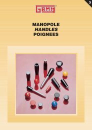
<strong>ROSTA</strong><br />
Rubber Suspension Unit<br />
Type DR-C<br />
Torque M in Nm at ) <br />
Weight<br />
Art. No. Type L L1 0<br />
– 0.3 A D S 5° 10° 15° 20° 25° 30° in kg<br />
01 031 010 DR-C 15 x 25 25 30 10 +0.4<br />
+ 0.2 27 +0.2<br />
– 0.1 15 0.7 1.6 2.6 4.0 5.7 8.2 0.06<br />
01 031 011 DR-C 15 x 40 40 45 10 +0.4<br />
+ 0.2 27 +0.2<br />
– 0.1 15 1.1 2.5 4.2 6.4 9.2 13.2 0.10<br />
01 031 012 DR-C 15 x 60 60 65 10 +0.4<br />
+ 0.2 27 +0.2<br />
– 0.1 15 1.6 3.8 6.3 9.6 13.8 19.8 0.15<br />
Rubber Suspension Units<br />
01 031 001 DR-C 18 x 30 30 35 13 – – 0.2 0.2<br />
32 +0.1<br />
– 0.2 18 1.9 4.5 7.5 11.0 15.0 20.6 0.10<br />
01 031 002 DR-C 18 x 50 50 55 13 – – 0.2 0.2<br />
32 +0.1<br />
– 0.2 18 3.2 7.5 12.5 18.3 25.0 34.4 0.16<br />
01 031 003 DR-C 18 x 80 80 85 13 – – 0.2 0.2<br />
32 +0.1<br />
– 0.2 18 5.1 12.0 20.0 29.3 40.0 55.0 0.25<br />
01 031 004 DR-C 27 x 40 40 45 16 +0.5<br />
+ 0.3 45 +0.2<br />
– 0.1 27 4.7 10.7 17.5 26.9 39.5 57.0 0.25<br />
01 031 005 DR-C 27 x 60 60 65 16 +0.5<br />
+ 0.3 45 +0.2<br />
– 0.1 27 7.0 16.0 26.3 40.3 59.3 85.5 0.36<br />
01 031 006 DR-C 27 x 100 100 105 16 +0.5<br />
+ 0.3 45 +0.2<br />
– 0.1 27 11.7 26.7 43.8 67.2 98.8 142.5 0.60<br />
01 031 007 DR-C 38 x 60 60 70 20 +0.5<br />
+ 0.2 60 + – 0.15<br />
0.3 38 13.0 30.4 50.6 78.0 113.0 162.0 0.60<br />
01 031 008 DR-C 38 x 80 80 90 20 +0.5<br />
+ 0.2 60 + – 0.15<br />
0.3 38 17.3 40.5 67.5 104.0 151.0 216.0 0.79<br />
01 031 009 DR-C 38 x 120 120 130 20 +0.5<br />
+ 0.2 60 + – 0.15<br />
0.3 38 26.0 60.8 101.2 156.0 226.0 324.0 1.16<br />
01 031 013 DR-C 45 x 80 80 90 24 +0.5<br />
+ 0.2 72 + – 0.15<br />
0.3 45 27.6 62.4 104.0 160.0 222.0 320.0 1.00<br />
01 031 014 DR-C 45 x 100 100 110 24 +0.5<br />
+ 0.2 72 + – 0.15<br />
0.3 45 34.5 78.0 130.0 200.0 278.0 400.0 1.22<br />
01 031 015 DR-C 50 x 120 120 130 30 +0.5<br />
+ 0.2 78 + 0.15<br />
– 0.3 50 51.0 133.0 250.0 395.0 570.0 780.0 1.80<br />
01 031 016 DR-C 50 x 200 200 210 30 +0.5<br />
+ 0.2 78 + 0.15<br />
– 0.3 50 102.0 260.0 475.0 745.0 1070.0 1450.0 3.00<br />
Bolted Lever Arm on Inner Square<br />
Positioning of the lever arm by means of central shaft screw<br />
and resulting frictional connection. Ideal for continuous<br />
positioning of the lever arm.<br />
This connection should not be applied at alternating oscillations<br />
by big angular motions ( ±10°).<br />
In order to get the most best frictional connection, the paint<br />
cover on the core front should be removed prior bolting<br />
any connection part.<br />
21
<strong>ROSTA</strong><br />
Rubber Suspension Unit<br />
Type DK-S<br />
Rubber Suspension Units<br />
Torque M in Nm at ) <br />
Weight<br />
Art. No. Type L L1 0<br />
– 0.3 C* D** E F S 5° 10° 15° 20° 25° 30° in kg<br />
01 081 001 DK-S 11 x 20 20 25 8 + + 0.25<br />
0.25 28 +0.3<br />
– 0.1 4 2.5 11 0.3 0.8 1.3 2.0 2.9 4.0 0.03<br />
01 081 002 DK-S 11 x 30 30 35 8 + + 0.25<br />
0.25 28 +0.3<br />
– 0.1 4 2.5 11 0.4 1.2 2.0 3.1 4.3 6.0 0.05<br />
01 081 003 DK-S 11 x 50 50 55 8 + + 0.25<br />
0.25 28 +0.3<br />
– 0.1 4 2.5 11 0.7 2.0 3.4 5.1 7.2 10.0 0.07<br />
01 081 004 DK-S 15 x 25 25 30 11 + + 0.25<br />
0.25 36 +0.3<br />
– 0.1 5 2.5 15 0.7 1.6 2.6 4.0 5.7 8.2 0.06<br />
01 081 005 DK-S 15 x 40 40 45 11 + + 0.25<br />
0.25 36 +0.3<br />
– 0.1 5 2.5 15 1.1 2.5 4.2 6.4 9.2 13.2 0.10<br />
01 081 006 DK-S 15 x 60 60 65 11 + + 0.25<br />
0.25 36 +0.3<br />
– 0.1 5 2.5 15 1.6 3.8 6.3 9.6 13.8 19.8 0.14<br />
01 081 007 DK-S 18 x 30 30 35 12 + + 0.25<br />
0.25 45 +0.4<br />
– 0.1 5 2.5 18 1.9 4.5 7.5 11.0 15.0 20.6 0.13<br />
01 081 008 DK-S 18 x 50 50 55 12 + + 0.25<br />
0.25 45 +0.4<br />
– 0.1 5 2.5 18 3.2 7.5 12.5 18.3 25.0 34.4 0.20<br />
01 081 009 DK-S 18 x 80 80 85 12 + + 0.25<br />
0.25 45 +0.4<br />
– 0.1 5 2.5 18 5.1 12.0 20.0 29.3 40.0 55.0 0.33<br />
01 081 010 DK-S 27 x 40 40 45 22 + + 0.25<br />
0.25 62 +0.5<br />
– 0.1 6 3.5 27 4.7 10.7 17.5 26.9 39.5 57.0 0.27<br />
01 081 011 DK-S 27 x 60 60 65 22 + + 0.25<br />
0.25 62 +0.5<br />
– 0.1 6 3.5 27 7.0 16.0 26.3 40.3 59.3 85.5 0.40<br />
01 081 012 DK-S 27 x 100 100 105 22 + + 0.25<br />
0.25 62 +0.5<br />
– 0.1 6 3.5 27 11.7 26.7 43.8 67.2 98.8 142.5 0.66<br />
01 081 013 DK-S 38 x 60 60 70 30 + + 0.25<br />
0.25 80 +0.6<br />
– 0.1 7 3.5 38 13.0 30.4 50.6 78.0 113.0 162.0 0.72<br />
01 081 014 DK-S 38 x 80 80 90 30 + + 0.25<br />
0.25 80 +0.6<br />
– 0.1 7 3.5 38 17.3 40.5 67.5 104.0 151.0 216.0 0.94<br />
01 081 015 DK-S 38 x 120 120 130 30 + + 0.25<br />
0.25 80 +0.6<br />
– 0.1 7 3.5 38 26.0 60.8 101.2 156.0 226.0 324.0 1.37<br />
01 081 016 DK-S 45 x 80 80 90 35 + + 0.25<br />
0.25 95 +0.8<br />
– 0.1 8 4.5 45 27.6 62.4 104.0 160.0 222.0 320.0 1.35<br />
01 081 017 DK-S 45 x 100 100 110 35 + + 0.25<br />
0.25 95 +0.8<br />
– 0.1 8 4.5 45 34.5 78.0 130.0 200.0 278.0 400.0 1.65<br />
01 081 018 DK-S 45 x 150 150 160 35 + + 0.25<br />
0.25 95 +0.8<br />
– 0.1 8 4.5 45 51.8 117.0 195.0 300.0 420.0 600.0 2.44<br />
01 081 019 DK-S 50 x 120 120 130 40 + + 0.25<br />
0.25 108 +1.0<br />
+ 0.1 8 4.5 50 51.0 133.0 250.0 395.0 570.0 780.0 2.55<br />
01 081 020 DK-S 50 x 200 200 210 40 + + 0.25<br />
0.25 108 +1.0<br />
+ 0.1 8 4.5 50 102.0 260.0 475.0 745.0 1070.0 1450.0 4.21<br />
01 081 021 DK-S 50 x 300 300 310 40 + 0.25<br />
+ 0.25 108 +1.0<br />
+ 0.1 8 4.5 50 150.0 385.0 700.0 1100.0 1590.0 2160.0 6.45<br />
* Plug-in connection “inserted” see page 19.<br />
** Frictional “Fist” Connection on Outer Housing<br />
The round outer housing can be either positioned by means<br />
of a clamping jaw or inserted into a “fist”-bracket. The<br />
tolerances of the outer housing diameter as well as the<br />
thickness of the protection paint (40 to 80 µm) have to be<br />
taken in consideration.<br />
22
<strong>ROSTA</strong><br />
Rubber Suspension Unit<br />
Type DK-A<br />
Ø 20 +0.5<br />
0 (Type DK-A 50)<br />
Torque M in Nm at ) <br />
Weight<br />
Art. No. Type L L1 0<br />
– 0.3 A +0.5<br />
+ 0.5 B D E F S 5° 10° 15° 20° 25° 30° in kg<br />
01 071 001 DK-A 15 x 25 25 30 5 10 ± 0.2 36 +0.3<br />
– 0.1 5 2.5 15 0.7 1.6 2.6 4.0 5.7 8.2 0.05<br />
01 071 002 DK-A 15 x 40 40 45 5 10 ± 0.2 36 +0.3<br />
– 0.1 5 2.5 15 1.1 2.5 4.2 6.4 9.2 13.2 0.08<br />
01 071 003 DK-A 15 x 60 60 65 5 10 ± 0.2 36 +0.3<br />
– 0.1 5 2.5 15 1.6 3.8 6.3 9.6 13.8 19.8 0.12<br />
Rubber Suspension Units<br />
01 071 004 DK-A 18 x 30 30 35 6 12 ± 0.3 45 +0.4<br />
– 0.1 5 2.5 18 1.9 4.5 7.5 11.0 15.0 20.6 0.10<br />
01 071 005 DK-A 18 x 50 50 55 6 12 ± 0.3 45 +0.4<br />
– 0.1 5 2.5 18 3.2 7.5 12.5 18.3 25.0 34.4 0.16<br />
01 071 006 DK-A 18 x 80 80 85 6 12 ± 0.3 45 +0.4<br />
– 0.1 5 2.5 18 5.1 12.0 20.0 29.3 40.0 55.0 0.26<br />
01 071 007 DK-A 27 x 40 40 45 8 20 ± 0.4 62 +0.5<br />
– 0.1 6 3.0 27 4.7 10.7 17.5 26.9 39.5 57.0 0.25<br />
01 071 008 DK-A 27 x 60 60 65 8 20 ± 0.4 62 +0.5<br />
– 0.1 6 3.0 27 7.0 16.0 26.3 40.3 59.3 85.5 0.37<br />
01 071 009 DK-A 27 x 100 100 105 8 20 ± 0.4 62 +0.5<br />
– 0.1 6 3.0 27 11.7 26.7 43.8 67.2 98.8 142.5 0.62<br />
01 071 010 DK-A 38 x 60 60 70 10 25 ± 0.4 80 +0.6<br />
– 0.1 7 3.5 38 13.0 30.4 50.6 78.0 113.0 162.0 0.63<br />
01 071 011 DK-A 38 x 80 80 90 10 25 ± 0.4 80 +0.6<br />
– 0.1 7 3.5 38 17.3 40.5 67.5 104.0 151.0 216.0 0.83<br />
01 071 012 DK-A 38 x 120 120 130 10 25 ± 0.4 80 +0.6<br />
– 0.1 7 3.5 38 26.0 60.8 101.2 156.0 226.0 324.0 1.22<br />
01 071 013 DK-A 45 x 80 80 90 12 35 ± 0.5 95 +0.8<br />
– 0.1 8 4.0 45 27.6 62.4 104.0 160.0 222.0 320.0 1.15<br />
01 071 014 DK-A 45 x 100 100 110 12 35 ± 0.5 95 +0.8<br />
– 0.1 8 4.0 45 34.5 78.0 130.0 200.0 278.0 400.0 1.44<br />
01 071 015 DK-A 45 x 150 150 160 12 35 ± 0.5 95 +0.8<br />
– 0.1 8 4.0 45 51.8 117.0 195.0 300.0 420.0 600.0 2.12<br />
01 071 016 DK-A 50 x 120 120 130 M12 x 40 40 ± 0.5 108 +1.0<br />
– 0.1 8 4.0 50 51.0 133.0 250.0 395.0 570.0 780.0 2.35<br />
01 071 017 DK-A 50 x 200 200 210 M12 x 40 40 ± 0.5 108 +1.0<br />
– 0.1 8 4.0 50 102.0 260.0 475.0 745.0 1070.0 1460.0 3.75<br />
01 071 018 DK-A 50 x 300 300 310 M12 x 40 40 ± 0.5 108 +1.0<br />
– 0.1 8 4.0 50 150.0 385.0 700.0 1100.0 1590.0 2160.0 5.60<br />
Fixation by Clamp Type BK<br />
The fixation of the outer housing by means of the standardized<br />
clamp type BK makes the continuous and individual<br />
pretension of the unit in both directions easy and adjustable<br />
(clamp type BK on page 27).<br />
23
<strong>ROSTA</strong><br />
Rubber Suspension Unit<br />
Type DO-S<br />
Rubber Suspension Units<br />
Torque M in Nm at ) <br />
Weight<br />
Art. No. Type L L1 0<br />
– 0.3 C D E F S 5° 10° 15° 20° 25° 30° in kg<br />
01 051 001 DO-S 15 x 25 25 30 11 + – 0.1 0.25<br />
28 ±0.15 25.5 53.5 ± 0.2 15 0.7 1.6 2.6 4.0 5.7 8.2 0.10<br />
01 051 002 DO-S 15 x 40 40 45 11 + – 0.1 0.25<br />
28 ±0.15 25.5 53.5 ± 0.2 15 1.1 2.5 4.2 6.4 9.2 13.2 0.14<br />
01 051 003 DO-S 15 x 60 60 65 11 + – 0.1 0.25<br />
28 ±0.15 25.5 53.5 ± 0.2 15 1.6 3.8 6.3 9.6 13.8 19.8 0.21<br />
01 051 004 DO-S 18 x 30 30 35 12 + – 0.1 0.25<br />
34 ±0.15 31.5 65 +0.2<br />
– 0.1 18 1.9 4.5 7.5 11.0 15.0 20.6 0.17<br />
01 051 005 DO-S 18 x 50 50 55 12 + – 0.1 0.25<br />
34 ±0.15 31.5 65 +0.2<br />
– 0.1 18 3.2 7.5 12.5 18.3 25.0 34.4 0.29<br />
01 051 006 DO-S 18 x 80 80 85 12 + – 0.1 0.25<br />
34 ±0.15 31.5 65 +0.2<br />
– 0.1 18 5.1 12.0 20.0 29.3 40.0 55.0 0.45<br />
01 051 007 DO-S 27 x 40 40 45 22 + – 0.1 0.25<br />
47 ±0.15 44.5 91 +0.2<br />
– 0.1 27 4.7 10.7 17.5 26.9 39.5 57.0 0.35<br />
01 051 008 DO-S 27 x 60 60 65 22 + – 0.1 0.25<br />
47 ±0.15 44.5 91 +0.2<br />
– 0.1 27 7.0 16.0 26.3 40.3 59.3 85.5 0.52<br />
01 051 009 DO-S 27 x 100 100 105 22 + – 0.1 0.25<br />
47 ±0.15 44.5 91 +0.2<br />
– 0.1 27 11.7 26.7 43.8 67.2 98.8 142.5 0.86<br />
01 051 010 DO-S 38 x 60 60 70 30 + – 0.1 0.25<br />
63 ±0.20 60.5 123 +0.3<br />
– 0.1 38 13.0 30.4 50.6 78.0 113.0 162.0 1.03<br />
01 051 011 DO-S 38 x 80 80 90 30 + – 0.1 0.25<br />
63 ±0.20 60.5 123 +0.3<br />
– 0.1 38 17.3 40.5 67.5 104.0 151.0 216.0 1.35<br />
01 051 012 DO-S 38 x 120 120 130 30 + – 0.1 0.25<br />
63 ±0.20 60.5 123 +0.3<br />
– 0.1 38 26.0 60.8 101.2 156.0 226.0 324.0 2.00<br />
01 051 013 DO-S 45 x 80 80 90 35 + – 0.1 0.25<br />
85 ±0.15 73.5 149.4 +1.6<br />
– 0.4 45 27.6 62.4 104.0 160.0 222.0 320.0 2.20<br />
01 051 014 DO-S 45 x 100 100 110 35 + – 0.1 0.25<br />
85 ±0.15 73.5 149.4 +1.6<br />
– 0.4 45 34.5 78.0 130.0 200.0 278.0 400.0 2.65<br />
01 051 015 DO-S 45 x 150 150 160 35 + – 0.1 0.25<br />
85 ±0.15 73.5 149.4 +1.6<br />
– 0.4 45 51.8 117.0 195.0 300.0 420.0 600.0 3.96<br />
01 051 016 DO-S 50 x 120 120 130 40 + 0.25<br />
– 0.1 89 ±0.15 78.5 167 50 51.0 133.0 250.0 395.0 570.0 780.0 5.67<br />
* DO-S 45 with convex housing shape<br />
Serial Connection<br />
Arrangements according to fig. I and II offer a doubled<br />
oscillating angle (± 60°) at constant torque of a single unit.<br />
24
<strong>ROSTA</strong><br />
Rubber Suspension Unit<br />
Type DO-A<br />
Only DO-A 50 size<br />
Ø 20 +0.5<br />
0 (Type DO-A 50)<br />
Torque M in Nm at ) Weight<br />
Art. No. Type L L1 0<br />
– 0.3 A +0.5<br />
0 B D E F S 5° 10° 15° 20° 25° 30° in kg<br />
01 041 001 DO-A 15 x 25 25 30 5 10 ± 0.2 28 ±0.15 25.5 53.5 ± 0.2 15 0.7 1.6 2.6 4.0 5.7 8.2 0.07<br />
01 041 002 DO-A 15 x 40 40 45 5 10 ± 0.2 28 ±0.15 25.5 53.5 ± 0.2 15 1.1 2.5 4.2 6.4 9.2 13.2 0.10<br />
01 041 003 DO-A 15 x 60 60 65 5 10 ± 0.2 28 ±0.15 25.5 53.5 ± 0.2 15 1.6 3.8 6.3 9.6 13.8 19.8 0.15<br />
Rubber Suspension Units<br />
01 041 004 DO-A 18 x 30 30 35 6 12 ± 0.3 34 ±0.15 31.0 65 +0.2<br />
– 0.1 18 1.9 4.5 7.5 11.0 15.0 20.6 0.12<br />
01 041 005 DO-A 18 x 50 50 55 6 12 ± 0.3 34 ±0.15 31.0 65 +0.2<br />
– 0.1 18 3.2 7.5 12.5 18.3 25.0 34.4 0.20<br />
01 041 006 DO-A 18 x 80 80 85 6 12 ± 0.3 34 ±0.15 31.0 65 +0.2<br />
– 0.1 18 5.1 12.0 20.0 29.3 40.0 55.0 0.30<br />
01 041 007 DO-A 27 x 40 40 45 8 20 ± 0.4 47 ±0.15 44.0 91 +0.2<br />
– 0.1 27 4.7 10.7 17.5 26.9 39.5 57.0 0.32<br />
01 041 008 DO-A 27 x 60 60 65 8 20 ± 0.4 47 ±0.15 44.0 91 +0.2<br />
– 0.1 27 7.0 16.0 26.3 40.3 59.3 85.5 0.47<br />
01 041 009 DO-A 27 x 100 100 105 8 20 ± 0.4 47 ±0.15 44.0 91 +0.2<br />
– 0.1 27 11.7 26.7 43.8 67.2 98.8 142.5 0.78<br />
01 041 010 DO-A 38 x 60 60 70 10 25 ± 0.4 63 ± 0.2 60.0 123 +0.3<br />
– 0.1 38 13.0 30.4 50.6 78.0 113.0 162.0 0.87<br />
01 041 011 DO-A 38 x 80 80 90 10 25 ± 0.4 63 ± 0.2 60.0 123 +0.3<br />
– 0.1 38 17.3 40.5 67.5 104.0 151.0 216.0 1.15<br />
01 041 012 DO-A 38 x 120 120 130 10 25 ± 0.4 63 ± 0.2 60.0 123 +0.3<br />
– 0.1 38 26.0 60.8 101.2 156.0 226.0 324.0 1.68<br />
01 041 013 DO-A 45 x 80 80 90 12 35 ± 0.5 85 ± 0.2 73.0 149.4 +1.6<br />
– 0.4 45 27.6 62.4 104.0 160.0 222.0 320.0 1.85<br />
01 041 014 DO-A 45 x 100 100 110 12 35 ± 0.5 85 ± 0.2 73.0 149.4 +1.6<br />
– 0.4 45 34.5 78.0 130.0 200.0 278.0 400.0 2.25<br />
01 041 015 DO-A 45 x 150 150 160 12 35 ± 0.5 85 ± 0.2 73.0 149.4 +1.6<br />
– 0.4 45 51.8 117.0 195.0 300.0 420.0 600.0 3.35<br />
01 041 016 DO-A 50 x 120 120 130 M12 40 ± 0.5 89 ± 0.2 78.0 167 50 51.0 133.0 250.0 395.0 570.0 780.0 5.50<br />
01 041 017 DO-A 50 x 200 200 210 M12 40 ± 0.5 89 ± 0.2 78.0 167 50 102.0 260.0 475.0 745.0 1070.0 1450.0 8.50<br />
* DO-A 45 with convex housing shape<br />
Parallel Connection<br />
Arrangements according to fig. I and II offer the doubled<br />
torque momentum at constant oscillating angle of ± 30°.<br />
25
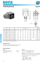
<strong>ROSTA</strong><br />
Rubber Suspension Unit<br />
Type DW-A<br />
D<br />
B<br />
S<br />
DW-A 60 to100<br />
L1<br />
L<br />
Q<br />
B<br />
A<br />
Ø I<br />
G<br />
H<br />
K<br />
N<br />
M<br />
P<br />
O<br />
Rubber Suspension Units<br />
DW-A 45 x 100 DW-A 50 x 200<br />
DW-A 50 x 120<br />
(Outer housing made out of spheroidal graphite cast iron)<br />
Weight<br />
Art. No. Type L L1 0<br />
– 0.3 A B D G H I K M N O P Q S T U in kg<br />
01 101 015 DW-A 45 x 100 100 110 Ø12 35 ± 0.5 78 115 145 – 22.5 65 – 8 – 41 45 13 20 2.9<br />
01 101 013 DW-A 50 x 120 120 130 M12 x 40 40 ± 0.5 87 130 170 17 x 27 35 60 – 12 – 45 50 17 27 3.7<br />
01 101 014 DW-A 50 x 200 200 210 M12 x 40 40 ± 0.5 87 130 170 17 x 27 35 70 – 12 – 45 50 17 27 6.1<br />
01 101 001 DW-A 60 x 150 150 160 M16 x 22 45 100 160 220 Ø18 50 60 60 8 130 65 60 – – 9.5<br />
01 101 002 DW-A 60 x 200 200 210 M16 x 22 45 100 160 220 Ø18 55 100 60 8 170 65 60 – – 11.8<br />
01 101 003 DW-A 60 x 300 300 310 M16 x 22 45 100 160 220 Ø18 55 200 60 8 270 65 60 – – 16.6<br />
01 101 004 DW-A 70 x 200 200 210 M20 x 28 50 120 200 260 Ø22 55 100 65 9 170 80 70 – – 16.6<br />
01 101 005 DW-A 70 x 300 300 310 M20 x 28 50 120 200 260 Ø22 55 200 65 9 270 80 70 – – 23.0<br />
01 101 006 DW-A 70 x 400 400 410 M20 x 28 50 120 200 260 Ø22 55 300 65 9 370 80 70 – – 29.5<br />
01 101 007 DW-A 80 x 200 200 210 M20 x 28 60 136 220 280 Ø22 65 80 80 10 170 85 80 – – 22.9<br />
01 101 008 DW-A 80 x 300 300 310 M20 x 28 60 136 220 280 Ø22 65 180 80 10 270 85 80 – – 31.7<br />
01 101 009 DW-A 80 x 400 400 410 M20 x 28 60 136 220 280 Ø22 65 280 80 10 370 85 80 – – 40.6<br />
01 101 010 DW-A 100 x 250 250 260 M24 x 32 75 170 300 380 Ø26 75 110 100 12 220 110 100 – – 45.7<br />
01 101 011 DW-A 100 x 400 400 410 M24 x 32 75 170 300 380 Ø26 75 260 100 12 370 110 100 – – 66.7<br />
01 101 012 DW-A 100 x 500 500 510 M24 x 32 75 170 300 380 Ø26 75 360 100 12 470 110 100 – – 80.7<br />
Torque M in Nm at<br />
Art. No. Type 5° 10° 15° 20° 25° 30°<br />
01 101 015 DW-A 45 x 100 34.5 78 130 200 278 400<br />
01 101 013 DW-A 50 x 120 51 133 250 395 570 780<br />
01 101 014 DW-A 50 x 200 102 260 475 745 1070 1450<br />
01 101 001 DW-A 60 x 150 75 170 300 460 700 1010<br />
01 101 002 DW-A 60 x 200 95 220 385 610 930 1380<br />
01 101 003 DW-A 60 x 300 140 365 630 995 1550 2240<br />
01 101 004 DW-A 70 x 200 140 380 650 1040 1490 2120<br />
01 101 005 DW-A 70 x 300 190 525 910 1470 2160 3150<br />
01 101 006 DW-A 70 x 400 250 765 1315 2160 3175 4750<br />
01 101 007 DW-A 80 x 200 200 500 850 1300 1900 2700<br />
01 101 008 DW-A 80 x 300 300 800 1300 2000 2900 4100<br />
01 101 009 DW-A 80 x 400 400 1060 1800 2800 3900 5600<br />
01 101 010 DW-A 100 x 250 400 1080 1800 2800 4100 6300<br />
01 101 011 DW-A 100 x 400 640 1700 2900 4500 6600 10000<br />
01 101 012 DW-A 100 x 500 800 2160 3600 5600 8200 12000<br />
26
<strong>ROSTA</strong><br />
Rubber Suspension Unit<br />
Accessories<br />
Clamp Type BR<br />
Weight<br />
Art. No. Type D G H I K M in kg<br />
01 500 001 BR 11 20 37 50 6 20 2.5 0.03<br />
01 500 002 BR 15 27 50 65 7 25 2.5 0.04<br />
01 500 003 BR 18 32 60 80 9 30 2.5 0.08<br />
01 500 004 BR 27 45 80 105 11 35 3.5 0.15<br />
01 500 005 BR 38 60 100 125 13 40 4.5 0.27<br />
01 500 006 BR 45 72 115 145 13 45 5.5 0.45<br />
01 500 007 BR 50 78 130 170 18 50 6.5 0.66<br />
Clamp Type BK<br />
Rubber Suspension Units<br />
Weight<br />
Art. No. Type D G H I K M N O in kg<br />
01 520 001 BK 11 28 45 60 6.5 20 1.5 6 15.5 0.04<br />
01 520 002 BK 15 36 55 75 6.5 25 2.0 7 20 0.09<br />
01 520 003 BK 18 45 68 90 8.5 30 2.0 8 24.5 0.14<br />
01 520 004 BK 27 62 92 125 10.5 35 2.5 10 33.5 0.29<br />
01 520 005 BK 38 80 115 150 12.5 40 3.0 11 43 0.45<br />
01 520 006 BK 45 95 130 165 12.5 45 3.5 13 51 0.68<br />
01 520 007 BK 50 108 152 195 16.5 50 4.0 15 58 0.93<br />
Bracket Type WS<br />
F<br />
fit for<br />
Weight<br />
Art. No. Type SE- DR-A, … A B C D E F G H J K L M N O in kg<br />
06 590 001 WS 11 – 15 11 15 6.5 5.5 7.5 7.5 30 13.5 11.5 27 4 45 30 46 35 10 0.08<br />
06 590 002 WS 15 – 18 15 18 8.5 6.5 7.5 7.5 40 13.5 13.5 34 5 55 32 58 44 12 0.15<br />
06 590 003 WS 18 – 27 18 27 10.5 8.5 9.5 10.5 50 15.5 16.5 43 6 70 38 74 55 20 0.28<br />
06 590 004 WS 27 – 38 27 38 12.5 10.5 11.5 12.5 65 21.5 21.5 57 8 90 52 98 75 25 0.70<br />
06 590 005 WS 38 – 45 38 45 16.5 12.5 14.5 15.5 80 24.5 21.5 66 8 110 55 116 85 35 0.90<br />
06 590 006 WS 45 – 50 45 50 20.5 12.5 18.5 20.5 100 30.5 26.5 80 10 140 66 140 110 40 1.80<br />
Bore A is designed for the fixation of the <strong>ROSTA</strong> tensioner devices type SE. Bores B are designed for the fixation of the <strong>ROSTA</strong> rubber suspension units type DR-A, DK-A, DO-A.<br />
27
<strong>ROSTA</strong><br />
Installations<br />
Rubber Suspension Units<br />
Lever bearing in concrete mixer Pressure rollers in saw device Pendulum on harrow rollers<br />
Conveyor-belt scraper Handle-bar insulation See-saw support<br />
Elastical brush and scraper suspension Suspended crane rail Shock absorber<br />
Control unit insulation Chain and belt tensioner Independent wheel suspension<br />
28
<strong>ROSTA</strong><br />
Installations<br />
Pendulum on amusement ride Compensation bearing for car brush Impact suspension in feeder<br />
Rubber Suspension Units<br />
Double suspension Motor base Shaker conveyor<br />
Compactor-suspension Guide rail Suspended pawl<br />
Impact-idler suspension Passive insulation Suspended unbalanced motor<br />
29
<strong>ROSTA</strong><br />
Fixation and Connecting Recommendations<br />
Fixations to Housing<br />
Rubber Suspension Units<br />
Fig. 1 Square tubular housing with clamp BR Fig. 2 Round housing with clamp BK<br />
Fig. 3<br />
Outer housing in clamping jaw<br />
Fig. 4<br />
Double bracket welded on housing<br />
Fig. 5 Plug-in connection (also see page 19) Fig. 6 Dual-thread welded on housing<br />
Fig. 7 Dual-levers welded on housing Fig. 8 Bridge-clamp over housing<br />
Fig. 9 Flange welded on housing Fig. 10 Housing in cast iron<br />
30
<strong>ROSTA</strong><br />
Fixation and Connecting Recommendations<br />
Fixations to Inner Square Section<br />
Fig. 11<br />
Inner square section with four through bores<br />
and bracket UV<br />
Fig. 12<br />
Inner square section with four through bores<br />
and brackets WS<br />
Rubber Suspension Units<br />
Fig. 13<br />
Plug-in connection with lever and welded-on<br />
square steel piece<br />
Fig. 14<br />
Lever connection with one through bolt<br />
Fig. 15<br />
Inner square section made of solid metal and machined<br />
threads on both sides<br />
Fig. 16<br />
Inner square section made of solid metal and cross bores<br />
on both protruding sides<br />
Fig. 17<br />
Inner square section with four through bores<br />
and bolted-on lever (see page 20)<br />
Fig. 18<br />
Inner square section made of solid steel<br />
and welded-on bracket<br />
Fig. 19 Inner square section with a central through bore (see page 21) Fig. 20 Inner square section made of solid steel and welded-on flange<br />
31
<strong>ROSTA</strong><br />
Applications<br />
Rubber Suspension Units<br />
Elastic stop to absorb high impacts Elastic suspension of a rake Suspension of a brush in road sweeper<br />
in potato harvester<br />
Elastic suspension of caliper roll in elevator<br />
“Floating” suspension of weighing device in belt conveyor<br />
Elastic suspension of shaping knive in baler<br />
Elastic caliper roll suspension in cardboard rolling machine<br />
32