TORQUE LIMITERS
TORQUE LIMITERS
TORQUE LIMITERS

Create successful ePaper yourself
Turn your PDF publications into a flip-book with our unique Google optimized e-Paper software.
COMPACT AND BACKLASH FREE.<br />
single-position<br />
multi-position<br />
load holding<br />
full disengagement<br />
<strong>TORQUE</strong> <strong>LIMITERS</strong><br />
SERIES SK + ES | 0.1 – 2,800 Nm<br />
THE ULTIMATE COUPLING FROM 0.1 – 2,800 Nm<br />
www.rwcouplings.com
single-position<br />
multi-position<br />
load holding<br />
full disengagement<br />
BACKLASH-FREE <strong>TORQUE</strong> <strong>LIMITERS</strong><br />
Areas of application<br />
■ Machine tools<br />
■ CNC machining centers<br />
■ Woodworking machines<br />
■ Automation equipment<br />
■ Textile machinery<br />
■ Industrial robots<br />
■ Sheet metal processing machines<br />
■ Printing + Converting machinery<br />
■ Servo + DC motor drives<br />
Features<br />
■ Precise overload protection<br />
■ Absolutely backlash-free and torsionally rigid (R+W patented principle)<br />
■ Compact, simple design<br />
■ Disengagement detection is achieved through indexing ring movement<br />
■ Low residual friction following disengagement<br />
■ Low moment of inertia<br />
■ Disengagement within msecs<br />
MODELS FEATURES POSSIBLE APPLICATIONS<br />
SK 1<br />
With conical clamp or<br />
clamping hub<br />
Spindle<br />
Conical clamp<br />
■ Integral bearings for timing belt<br />
pulley or sprocket<br />
■ Compact, simple design<br />
■ Adjustable settings<br />
Motor<br />
see pages 6-7<br />
SKN<br />
With clamping hub<br />
for indirect drives<br />
Spindle<br />
Clamping hub<br />
■ Integral bearing for timing belt<br />
pulley or sprocket<br />
■ Compact, simple design<br />
■ Adjustable settings<br />
■ Frictional clamping hub<br />
■ Simple assembly<br />
Motor<br />
see pages 8-9<br />
SKP<br />
With keyway connection<br />
for indirect drives<br />
Spindle<br />
with keyway<br />
■ Integral bearings for timing belt<br />
pulley or sprocket<br />
■ Compact, simple design<br />
■ Adjustable settings<br />
Motor<br />
see pages 10-11<br />
SK 2<br />
With clamping hub for direct drives<br />
■ Easy assembly<br />
■ Low moment of inertia<br />
■ Compact<br />
■ Compensates for shaft misalignment<br />
■ Adjustable settings<br />
Motor<br />
Spindle<br />
see page 12<br />
2<br />
R+W<br />
www.rwcouplings.com
single-position<br />
multi-position<br />
load holding<br />
full disengagement<br />
MODELS FEATURES POSSIBLE APPLICATIONS<br />
SK 3<br />
With conical clamp connection<br />
for direct drives<br />
■ High clamping forces<br />
■ High degree of operational<br />
dependability<br />
■ Compensates for shaft misalignment<br />
■ Adjustable settings<br />
Motor<br />
see page 13<br />
Spindle<br />
SK 5<br />
With clamping hub, press-fit<br />
version for direct drives<br />
Motor<br />
Spindle<br />
■ Easy mounting and dismounting<br />
■ Electrically and thermally insulated<br />
■ Compensates for shaft misalignment<br />
■ Adjustable settings<br />
see pages 14-15<br />
ES 2<br />
With clamping hub for direct drives<br />
■ Easy assembly<br />
■ Damps vibrations<br />
■ Compensates for shaft misalignment<br />
■ Adjustable settings<br />
Motor<br />
Spindle<br />
see pages 16-17<br />
ESL<br />
Torque limiter „Economy Class“<br />
■ Cost effective<br />
■ Compact<br />
■ Multi-position<br />
Motor<br />
Spindle<br />
see page 18<br />
EEx<br />
For use in explosive environments<br />
■ EEx availabe for the entire product range<br />
■ for the hazardous areas 1/21 and 2/22<br />
the SERVOMAX EEx Elastomer couplings<br />
are registered according to the<br />
directive ATEX 95a<br />
see page 19<br />
www.rwcouplings.com<br />
R+W<br />
3
single-position<br />
multi-position<br />
load holding<br />
full disengagement<br />
OVERVIEW<br />
BACKLASH-FREE <strong>TORQUE</strong> <strong>LIMITERS</strong> FROM R+W<br />
Single-position re-engagement<br />
Standard version<br />
■ After the overload has been removed,<br />
the coupling will re-engage precisely 360 °<br />
from the original disengagement position.<br />
■ Signal at overload<br />
■ Suitable for use in machine tools, packaging<br />
machinery, automation systems and other<br />
applications requiring precise timing.<br />
Every model in this catalog<br />
is available in all 4 versions.<br />
■ Mechanical overload detection device<br />
Load holding Version<br />
Free rotation<br />
■ In the event of a torque overload, the drive and<br />
driven elements are not fully separated and are only<br />
allowed limited rotation.<br />
■ Guaranteed to hold the load and signal an overload.<br />
■ Automatic engagement after the torque level<br />
has dropped.<br />
■ Signal at overload to detect with mechanical switch or<br />
proximity sensor.<br />
■ Suitable for use on presses, load lifting equipment or<br />
on any applications where the drive and driven elements<br />
cannot be disengaged.<br />
4<br />
R+W<br />
www.rwcouplings.com
single-position<br />
multi-position<br />
load holding<br />
full disengagement<br />
POSSIBLE FUNCTION SYSTEMS<br />
Multi-position re-engagement<br />
■ Coupling re-engages at multiple set angular<br />
intervals.<br />
■ Immediate availability of the machine as soon as the<br />
overload has been removed.<br />
■ Signal at overload with mechanical switch or<br />
proximity sensor<br />
■ Standard engagement every 60°<br />
■ Re-engagement after 30, 45, 90 or 120 degrees<br />
available upon request<br />
Full disengagement<br />
Note:<br />
Coupling can be<br />
disengaged<br />
manually.<br />
Please contact<br />
R+W.<br />
■ Permanent separation of drive and driven elements<br />
in the event of a torque overload.<br />
■ Signal at overload with mechanical switch or<br />
proximity sensor<br />
■ No residual friction<br />
■ Rotating elements slow down freely<br />
■ Coupling can be re-engaged manually<br />
(Engagement every 60˚); other<br />
engagement intervals optional<br />
■ For use in high speed applications<br />
Disc spring in<br />
disengaged<br />
position<br />
www.rwcouplings.com<br />
R+W<br />
5
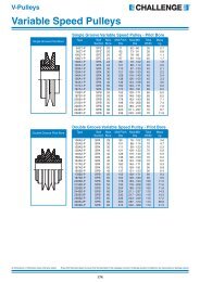
MODEL SK1<br />
BACKLASH FREE <strong>TORQUE</strong> LIMITER<br />
single-position<br />
multi-position<br />
load holding<br />
full disengagement<br />
Production<br />
monitored<br />
Type<br />
Testet<br />
with conical clamp connection<br />
Pulley not included.<br />
Miniature Design Series 1.5 - 10<br />
Standard clamping hub<br />
Ø G<br />
P<br />
H<br />
K<br />
J<br />
Actuation path (see table)<br />
Bore for spanner<br />
wrench<br />
Material:<br />
High strength, hardened steel<br />
Design:<br />
Model SK1 from 1.5 - 10 Nm with clamping hub<br />
Model SK1 von 15 - 2,800 Nm with conical clamp<br />
Absolutely backlash free through the frictional<br />
clamping connection<br />
Ø F ±0,2<br />
Ø E h7<br />
Ø O 1<br />
Ø O 2 h7<br />
Ø D H7<br />
Ø O<br />
Ø B/B F<br />
Temperature range:<br />
-30 to +120° C<br />
Service life:<br />
Maintenace free when operated within the<br />
technical specifications<br />
N<br />
ISO 4762<br />
Keyway available<br />
upon request<br />
R<br />
I<br />
L/L F<br />
A/A F<br />
M<br />
C<br />
Drawn<br />
offset<br />
Fit tolerance:<br />
Tolerance between hub and shaft 0.01 - 0.05 mm<br />
Optional sealed version for food-grade<br />
applications (see page 26)<br />
Design Series 15-2500<br />
Optional ATEX<br />
Standard conical clamp<br />
Ø B / B F<br />
Bore for spanner<br />
wrench<br />
H<br />
I Deep<br />
J<br />
K<br />
For actuation<br />
path (see table)<br />
Certified under the ATEX 95a directive for<br />
the hazardous zones 1/21 and 1/22<br />
Ø G<br />
Ø F ±0,2<br />
Ø E h7<br />
Ø O 1<br />
Ø O 2 h7<br />
Ø D H7<br />
C<br />
Ø D H7<br />
R<br />
N ISO 4762<br />
Thread for<br />
removal screw<br />
L/L F A/A F<br />
Ordering specifications<br />
SK1 / 10 / W / 14 / 4 / 2-6 / xx<br />
Model<br />
Series<br />
Version<br />
Bore Ø D H7<br />
Possible versions<br />
W = Single-position engagement<br />
D = Multi-position engagement<br />
G = Load holding<br />
F = Full disengagement<br />
Disengagement torque Nm<br />
Adjustment range Nm<br />
e.g. stainless steel<br />
All data is subject to change without notice.<br />
For the maximum permissible radial<br />
load capacity for all SK 1 models,<br />
see installation instructions on page 22/23<br />
6<br />
R+W<br />
www.rwcouplings.com
single-position<br />
multi-position<br />
load holding<br />
full disengagement<br />
Production<br />
monitored<br />
Type<br />
Testet<br />
MODEL SK 1<br />
Adjustment range<br />
available from - to<br />
(approx. values)<br />
(Nm)<br />
Adjustment range<br />
available from - to (approx. values)<br />
(”F” Version)<br />
(Nm)<br />
0.1-0.6<br />
T KN 0.4-1<br />
0.8-2<br />
Series<br />
1.5 2 4.5 10 15 30 60 150 200 300 500 800 1500 2500<br />
0.3-0.8<br />
T KN or<br />
0.6-1.3<br />
Miniature Design<br />
0.2-1.5<br />
0.5-2.2<br />
1.5-3.5<br />
1-3<br />
2-4.5<br />
3-7<br />
0.5-2 2.5-4.5<br />
2-6<br />
4-12<br />
7-18<br />
2-5<br />
4-10<br />
8-15<br />
5-15<br />
12-25<br />
20-40<br />
35-70<br />
7-15<br />
5-20<br />
10-30<br />
20-60<br />
50-100<br />
8-20<br />
or<br />
16-30<br />
10-30<br />
25-80<br />
50-115<br />
10-30<br />
20-40<br />
30-60<br />
20-70<br />
45-150<br />
80-225<br />
20-60<br />
40-80<br />
80-150<br />
30-90<br />
60-160<br />
140-280<br />
250-400<br />
80-140<br />
or<br />
130-200<br />
100-200<br />
150-240<br />
220-440<br />
120-180<br />
160-300<br />
300-450<br />
80-200<br />
200-350<br />
320-650<br />
50-150<br />
100-300<br />
250-500<br />
400-650<br />
500-800<br />
650-950<br />
200-400<br />
or<br />
450-850<br />
600-800<br />
700-1200<br />
1000-1800<br />
1000-1250<br />
or<br />
1250-1500<br />
1500-2000<br />
2000-2500<br />
2300-2800<br />
1400-2200<br />
or<br />
1800-2700<br />
Overall length (mm) A 23 28 32 39 40 50 54 58 63 70 84 95 109 146<br />
Overall length (”F” Version) (mm) A F 23 28 32 39 40 50 54 58 66 73 88 95 117 152<br />
Actuation ring Ø (mm) B 23 29 35 45 55 65 73 92 99 120 135 152 174 242<br />
Actuation ring Ø, (”F” Version) (mm) B F 24 32 42 51.5 62 70 83 98 117 132 155 177 187 258<br />
Clamping fit length (mm) C 7 8 11 11 19 22 27.5 32 32 41 41 49 61 80<br />
Inner diameter<br />
from Ø to Ø H7<br />
(mm)<br />
D 4-8 4-12 5-14 6-20 8-22 12-22 12-29 15-37 20-44 25-56 25-56 30-60 35-70 50-100<br />
Pilot diameter h7 (mm) E 14 22 25 34 40 47 55 68 75 82 90 100 125 168<br />
Bolt-hole circle diameter ± 0,2 (mm) F 22 28 35 43 47 54 63 78 85 98 110 120 148 202<br />
Flange outside diameter -0,2 (mm) G 26 32 40 50 53 63 72 87 98 112 128 140 165 240<br />
Thread H 4x M2 4x M2.5 6x M2.5 6x M3 6x M4 6x M5 6x M5 6x M6 6x M6 6x M8 6x M8 6x M10 6x M12 6x M16<br />
Thread depth (mm) I 3 4 4 5 6 8 9 10 10 10 12 15 16 24<br />
Centering length -0,2 (mm) J 2.5 3.5 5 8 3 5 5 5 5 6 9 10 13.5 20<br />
Distance (mm) K 5 6 8 11 8 11 11 12 12 15 21 19 25 34<br />
Distance (mm) L 11 15 17 22 27 35 37 39 44 47 59 67 82 112<br />
Distance (”F” Version) (mm) L F 11.5 16 18 24 27 37 39 41.5 47 51.5 62 75 94 120<br />
Distance M 3.5 4 5 5<br />
Screw ISO 4762<br />
1x M 2.5 1x M 3 1x M 4 1x M 4 6x M4 6x M5 6x M5 6x M6 6x M6 6x M8 6x M8 6x M10 6x M12 6x M16<br />
N<br />
Tightening torque (Nm) 1 2 4 4.5 4 6 8 12 14 18 25 40 70 120<br />
Outside diameter clamp ring Ø (mm) O 20 25 32 40<br />
Diameter (mm) O 1 13 18 21 30 35 42 49 62 67 75 84 91 112 154<br />
Diameter h7 (mm) O 2 11 14 17 24 27 32 39 50 55 65 72 75 92 128<br />
Distance between centers (mm) P 6.5 8 10 15<br />
Distance (mm) R 1 1.3 1.5 1.5 2.5 2.5 2.5 2.5 3 3 4 4 4.5 6<br />
Moment of inertia (10¯³ kgm²) J ges 0.01 0.02 0.05 0.07 0.15 0.25 0.50 1.60 2.70 5.20 8.60 20 31.5 210<br />
Approx. weight (kg) 0.03 0.065 0.12 0.22 0.4 0.7 1.0 1.3 2.0 3.0 4.0 5.5 10 28<br />
Actuation path (mm) 0.7 0.8 0.8 1.2 1.5 1.5 1.7 1.9 2.2 2.2 2.2 2.2 3.0 3.0<br />
A F , B F , L F = Full disengagement version<br />
www.rwcouplings.com<br />
R+W<br />
7
single-position<br />
multi-position<br />
load holding<br />
full disengagement<br />
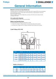
MODEL SKN<br />
Production<br />
monitored<br />
Type<br />
Testet<br />
Pulley not included.<br />
BACKLASH FREE <strong>TORQUE</strong> LIMITER<br />
with clamping hub<br />
Series 5 - 1800 Nm<br />
Ø B / B F<br />
Shown<br />
offset<br />
N<br />
ISO 4762<br />
H<br />
I Deep<br />
J<br />
K<br />
Actuation path (see table)<br />
Bore for spanner<br />
wrench<br />
Material:<br />
Torque limiting portion: high-strength, hardened steel<br />
Clamping hub: up to series 500, aluminium;<br />
from series 800, steel<br />
Design:<br />
With clamping hub and 1 radial screw ISO 4762<br />
Absolutely backlash free through frictional<br />
clamping connection<br />
Ø G<br />
Ø F ±0,2<br />
Ø E h7<br />
Ø O 1<br />
Ø O 2 h7<br />
Ø D H7<br />
Temperature range:<br />
-30 to +120° C<br />
Service life:<br />
Maintenance free when operated within the<br />
technical specifications<br />
Ø O<br />
P<br />
R<br />
L/L F<br />
A/A F<br />
C<br />
M<br />
Fit tolerance:<br />
Tolerance between hub an shaft 0.01 - 0.05 mm<br />
Optional sealed version for food-grade<br />
applications (see page 26)<br />
Easy mounting and dismounting<br />
Option ATEX<br />
Motor<br />
Clamping hub<br />
Clamping hub<br />
Certified under the ATEX 95a directive for<br />
the hazardous zones 1/21 and 1/22<br />
Clamping hub mounts on the<br />
motor shaft and tightens via a<br />
radial clamping screw.<br />
Ordering specifications<br />
SKN / 60 / W / 20 / 60/25-80 / xx<br />
Model<br />
Series<br />
Version<br />
Bore Ø D H7<br />
Possible versions<br />
W = Single-position engagement<br />
D = Multi-position engagement<br />
G = Load holding<br />
F = Full disengagement<br />
Disengagement torque Nm<br />
Adjustment range Nm<br />
e.g. stainless steel<br />
All data is subject to change without notice.<br />
For the maximum permissible radial<br />
load capacity for all SKN models,<br />
see installation instructions on page 22/2<br />
8<br />
R+W<br />
www.rwcouplings.com
single-position<br />
multi-position<br />
load holding<br />
full disengagement<br />
Production<br />
monitored<br />
Type<br />
Testet<br />
MODEL SKN<br />
15 30 60 150 200 300 500 800 1500<br />
Adjustment range<br />
available from - to<br />
T KN<br />
5-10<br />
or<br />
10-25<br />
or<br />
10-30<br />
or<br />
20-70<br />
45-150<br />
30-90<br />
60-160<br />
100-200<br />
150-240<br />
80-200<br />
200-350<br />
400-650<br />
500-800<br />
(approx. values)<br />
(Nm)<br />
8-20 20-40 25-80 80-180 120-240 200-320 300-500 600-850<br />
Adjustment range<br />
8-20 10-30 20-60 80-140 120-180 50-150 200-400<br />
available from - to (approx. values) T KN 7-15<br />
or 20-40 40-80 or<br />
or 100-300 or<br />
(”F” Version)<br />
(Nm)<br />
16-30 30-60 80-150 130-200 160-300 250-500 450-800<br />
Overall length (mm) A 47 59 65 71 80 84 101 115 145<br />
Overall length (”F” Version) (mm) A F 47 59 65 71 83 87 107 130 160<br />
Actuation ring Ø (mm) B 55 65 73 92 99 120 135 152 174<br />
Actuation ring Ø (”F” Version) (mm) B F 62 70 83 98 117 132 155 177 187<br />
Clamping fit length (mm) C 13.5 16 20 23 26 26 30 35 46<br />
600-800<br />
700-1200<br />
1000-1800<br />
1000-1250<br />
or<br />
1250-1500<br />
Inner diameter<br />
from Ø to Ø H7<br />
Inner Diameter from<br />
Ø to Ø H7 with keyway<br />
(mm)<br />
(mm)<br />
D 12-22 14-25.4 16-32 19-40 24-44 30-56 35-60 40-62 50-72<br />
D 8-19 12-25.4 12-30 15-38 20-44 25-50 25-58 30-60 35-72<br />
Pilot diameter h7 (mm) E 40 47 55 68 75 82 90 100 125<br />
Bolt-hole circle diameter ± 0,2 (mm) F 47 54 63 78 85 98 110 120 148<br />
Flange outside diameter -0,2 (mm) G 53 63 72 87 98 112 128 140 165<br />
Thread H 6xM4 6xM5 6xM5 6xM6 6xM6 6xM8 6xM8 6xM10 6xM12<br />
Thread depth (mm) I 6 8 9 10 10 10 12 15 16<br />
Centering length -0,2 (mm) J 3 5 5 5 5 6 9 10 13.5<br />
Distance (mm) K 8 11 11 12 12 15 21 19 25<br />
Distance (mm) L 27 35 37 39 44 47 59 67 82<br />
Distance (”F” Version) (mm) L F 27 37 39 41.5 47 51.5 62 75 94<br />
Distance M 6.5 7.5 9.5 11 13 13 14.5 18 22.5<br />
Screw ISO 4762<br />
M5 M6 M8 M10 M12 M12 M14 M16 M20<br />
N<br />
Tightening torque (Nm) 8 15 40 70 120 130 210 270 500<br />
Clamp ring Ø (mm) O 49 55 67 85 94 110 121 134 157<br />
Diameter (mm) O 1 35 42 49 62 67 75 84 91 112<br />
Diameter h7 (mm) O 2 27 36 39 50 55 65 72 75 92<br />
Distance between centers (mm) P 17.5 19 23.5 30 32.5 39 43.5 45 52<br />
Distance (mm) R 2.5 2.5 2.5 2.5 3 3 4 4 4.5<br />
Moment of inertia (10¯³ kgm²) J ges 0.15 0.25 0.50 1.60 2.70 5.20 8.60 20 31.5<br />
Approx. weight (kg) 0.4 0.7 1.0 1.3 2.0 3.0 4.0 5.5 10<br />
Actuation path (mm) 1.5 1.5 1.7 1.9 2.2 2.2 2.2 2.2 3.0<br />
A F , B F , L F = Full disengagement version<br />
www.rwcouplings.com<br />
R+W<br />
9
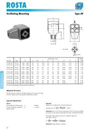
MODEL SKP<br />
BACKLASH FREE <strong>TORQUE</strong> LIMITER<br />
single-position<br />
multi-position<br />
load holding<br />
full disengagement<br />
Production<br />
monitored<br />
Type<br />
Testet<br />
With pure keyway connection<br />
Pulley not included.<br />
Miniature series 1.5 - 10<br />
With pure keyway connection<br />
HØ O 1 h7<br />
K<br />
J<br />
Actuation path (see table)<br />
Bore for spanner<br />
wrench<br />
Ø G<br />
Ø F ±0,2<br />
Material:<br />
High-strength, hardened steel<br />
Design:<br />
Pure keyway connection<br />
Torque limiting element is backlash free<br />
Temperature range:<br />
-30 to +120° C<br />
Ø E h7<br />
Ø O<br />
R<br />
I<br />
L/L F<br />
A/A F<br />
Ø D H7<br />
Ø B/B F<br />
Keyway<br />
DIN 6885<br />
Service life:<br />
Maintenance free when operated within the<br />
technical specifications<br />
Fit tolerance:<br />
Tolerance between hub and shaft 0.01 – 0.05 mm<br />
Optional sealed version for food-grade<br />
applications (see page 26)<br />
Series 15-2500<br />
Option ATEX<br />
With pure keyway connection<br />
H<br />
I tief<br />
J<br />
K<br />
Actuation path see table<br />
Bore for spanner<br />
wrench<br />
Ø G<br />
Ø F ±0,2<br />
Certified under the ATEX 95a directive for<br />
the hazardous zones 1/21 and 1/22<br />
Ø E h7<br />
Ø O<br />
Ø O 1 h7<br />
Ø D H7<br />
Ø B/B F<br />
R<br />
L/L F<br />
A/A F<br />
Keyway<br />
DIN 6885<br />
Ordering specifications<br />
SKP / 10 / W / 14 / 4 / 2-6 / xx<br />
Model<br />
Series<br />
Version<br />
Bore Ø D H7<br />
Disengagement torque Nm<br />
Adjustment range Nm<br />
e.g. stainless steel<br />
All data is subject to change without notice.<br />
Possible versions<br />
W = Single-position engagement (standard)<br />
D = Multi-position engagement<br />
G = Load holding<br />
F = Full disengagement<br />
For the maximum permissible radial<br />
load capacity for all SKP models,<br />
see installation instructions on page 22/23<br />
10<br />
R+W<br />
www.rwcouplings.com
single-position<br />
multi-position<br />
load holding<br />
full disengagement<br />
Production<br />
monitored<br />
Type<br />
Testet<br />
MODEL SKP<br />
Adjustment range<br />
available from - to<br />
(approx. values)<br />
(Nm)<br />
0.1-0.6<br />
T KN 0.4-1<br />
0.8-2<br />
Miniature Design<br />
Series<br />
1.5 2 4.5 10 15 30 60 150 200 300 500 800 1500 2500<br />
0.2-1.5<br />
0.5-2.2<br />
1.5-3.5<br />
1-3<br />
2-4.5<br />
3-7<br />
2-6<br />
4-12<br />
7-18<br />
5-15<br />
12-25<br />
20-40<br />
35-70<br />
5-20<br />
10-30<br />
20-60<br />
50-100<br />
10-30<br />
25-80<br />
50-115<br />
20-70<br />
45-150<br />
80-225<br />
30-90<br />
60-160<br />
140-280<br />
250-400<br />
100-200<br />
150-240<br />
220-440<br />
80-200<br />
200-350<br />
320-650<br />
400-650<br />
500-800<br />
650-950<br />
600-800<br />
700-1200<br />
1000-1800<br />
1500-2000<br />
2000-2500<br />
2300-2800<br />
Adjustment range<br />
available from - to (approx. values)<br />
(”F” Version)<br />
(Nm)<br />
0.3-0.8<br />
T KN or<br />
0.6-1.3<br />
0.5-2 2.5-4.5<br />
2-5<br />
4-10<br />
8-15<br />
7-15<br />
8-20<br />
or<br />
16-30<br />
10-30<br />
20-40<br />
30-60<br />
20-60<br />
40-80<br />
80-150<br />
80-140<br />
or<br />
130-200<br />
120-180<br />
160-300<br />
300-450<br />
50-150<br />
100-300<br />
250-500<br />
200-400<br />
or<br />
450-850<br />
1000-1250<br />
or<br />
1250-1500<br />
1400-2200<br />
or<br />
1800-2700<br />
Overall length A (mm) A 15.5 20 22 28 34 43 46 48.5 54 57 71.5 80 93 135<br />
Overall length A (”F” Version) (mm) A F 15.5 20 22 28 34 43 46 48.5 57 60 75 91 110 141<br />
Actuation ring Ø (mm) B 23 29 35 45 55 65 73 92 99 120 135 152 174 242<br />
Actuation ring Ø, (”F” Version) (mm) B F 24 32 42 51.5 62 70 83 98 117 132 155 177 187 258<br />
Bore Diameter from Ø to Ø H7 (mm) D 4-8 4-10 5-12 6-16 8-19 12-25.4 12-30* 15-38 20-44 25-50 25-58 30-60 35-73 50-95<br />
Pilot diameter h7 (mm) E 14 22 25 34 40 47 55 68 75 82 90 100 125 168<br />
Bolt-hole circle diameter ± 0,2 (mm) F 22 28 35 43 47 54 63 78 85 98 110 120 148 202<br />
Flange outside diameter -0,2 (mm) G 26 32 40 50 53 63 72 87 98 112 128 140 165 240<br />
Thread H 4xM2 4xM2.5 6xM2.5 6xM3 6xM4 6xM5 6xM5 6xM6 6xM6 6xM8 6xM8 6xM10 6xM12 6xM16<br />
Thread depth (mm) I 3 4 4 5 6 8 9 10 10 10 12 15 16 24<br />
Centering length -0,2 (mm) J 2.5 3.5 5 8 3 5 5 5 5 6 9 10 13.5 20<br />
Distance (mm) K 5 6 8 11 8 11 11 12 12 15 21 19 25 34<br />
Distance (mm) L 11 15 17 22 27 35 37 39 44 47 59 67 82 112<br />
Distance (”F” Version) (mm) L F 11.5 16 18 24 27 37 39 41.5 47 51.5 62 75 94 120<br />
Diameter (mm) O 13 18 21 30 35 42 49 62 67 75 84 91 112 154<br />
Diameter h7 (mm) O 1 11 14 17 24 27 32 39 50 55 65 72 75 92 128<br />
Distance (mm) R 1 1.3 1.5 1.5 2.5 2.5 2.5 2.5 3 3 4 4 4.5 6<br />
Moment of inertia (10¯³ kgm²) J ges 0.01 0.02 0.05 0.07 0.15 0.25 0.50 1.60 2.70 5.20 8.60 20 31.5 210<br />
Approx. weight (kg) 0.03 0.065 0.12 0.22 0.4 0.7 1.0 1.3 2.0 3.0 4.0 5.5 10 28<br />
Actuation path (mm) 0.7 0.8 0.8 1.2 1.5 1.5 1.7 1.9 2.2 2.2 2.2 2.2 3.0 3.0<br />
A F , B F , L F = Full disengagement version *Ø 30 with flat keyway, keyway depth (t 2 ) 2.8 + 0.2<br />
Keyway according to the DIN 6885 Standard<br />
D 1<br />
from<br />
to<br />
6<br />
8<br />
8<br />
10<br />
10<br />
12<br />
12<br />
17<br />
17<br />
22<br />
22<br />
30<br />
30<br />
38<br />
38<br />
44<br />
44<br />
50<br />
50<br />
58<br />
58<br />
65<br />
65<br />
75<br />
75<br />
85<br />
85<br />
95<br />
95<br />
110<br />
Keyway width<br />
b JS9<br />
b JS9 2 3 4 5 6 8 10 12 14 16 18 20 22 25 28<br />
h 2 3 4 5 6 7 8 8 9 10 11 12 14 14 16<br />
t 1<br />
1.2 1.8 2.5 3 3.5 4 5 5 5.5 6 7 7.5 9 9 10<br />
+0,1 / +0,2<br />
t 2<br />
1 1.4 1.8 2.3 2.8 3.3 3.3 3.3 3.8 4.3 4.4 4.9 5.4 5.4 6.4<br />
Imperial dimension keyways also available.<br />
+0,1<br />
+0,2<br />
Keyway depth t 2<br />
t 1<br />
D 1<br />
h<br />
Height of key<br />
www.rwcouplings.com<br />
R+W 11
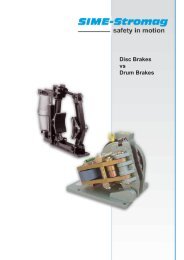
MODEL SK2<br />
BACKLASH FREE <strong>TORQUE</strong> LIMITER<br />
single-position<br />
multi-position<br />
load holding<br />
full disengagement<br />
Production<br />
monitored<br />
Type<br />
Testet<br />
with clamping hub<br />
G<br />
C<br />
Actuation path (see table)<br />
Bore for spanner wrench<br />
H<br />
Material:<br />
Bellows made of highly elastic stainless steel<br />
Torque limiter section: High strength hardened<br />
steel<br />
Hub material: up to series 80 aluminium from<br />
series up 150 steel<br />
Ø E<br />
Ø D 1<br />
H7<br />
C<br />
Ø D 2<br />
H7<br />
Ø B/B F<br />
Design:<br />
With clamping hub and 1 radial screw ISO 4762<br />
Absolutely backlash free through frictional<br />
clamping connection<br />
Temperature range:<br />
-30° C to +100° C<br />
ISO 4762<br />
A/A F<br />
G<br />
F/F F<br />
Keyway available<br />
upon request<br />
Service life:<br />
Maintenance free when operated within the<br />
technical specifications<br />
Fit tolerance:<br />
Tolerance between hub and shaft 0.01 – 0.05 mm<br />
Ordering specifications: see page 15<br />
Optional sealed version for food-grade<br />
applications (see page 26)<br />
Optional ATEX Certification (see page 19)<br />
Model SK 2<br />
12<br />
R+W<br />
Series<br />
1.5 2 4.5 10 15 30 60 80 150 200 300 500 800 1500<br />
Adjustment range<br />
0.1-0.6 0.2-1.5 1-3 2-6 5-10 10-25 10-30 20-70 20-70 30-90 100-200 80-200 400-650 650-800<br />
available from - to<br />
T KN 0.4-1 or or or or or or or 45-150 60-160 150-240 200-350 500-800 700-1200<br />
(approx. values)<br />
(Nm) 0.8-1.5 0.5-2 3-6 4-12 8-20 20-40 25-80 30-90 80-180 120-240 200-320 300-500 650-850 1000-1800<br />
Adjustment range<br />
0.3-0.8<br />
2-5<br />
8-20 20-40 20-60 20-60 80-140 120-180 60-150 200-400 1000-1250<br />
available from - to (approx. values) T KN or 0.5-2 2.5-4.5 or 7-15 or or or 40-80 or or 100-300 or or<br />
(”F” Version)<br />
(Nm) 0.6-1.3<br />
5-10<br />
16-30 30-60 40-80 80-150 130-200 160-300 250-500 450-800 1250-1500<br />
Overall length (mm) A 42 46 51 57 65 65 74 75 82 87 95 102 112 115 127 116 128 128 140 139 153 163 177 190 223<br />
Overall length,<br />
(”F” Version)<br />
(mm)<br />
A F 42 46 51 57 65 65 74 75 82 87 95 102 112 117 129 118 130 131 143 142 156 167 181 201 232<br />
Actuation ring Ø (mm) B 23 29 35 45 55 65 73 92 92 99 120 135 152 174<br />
Actuation ring Ø<br />
(ful disengagement)<br />
(mm)<br />
B F 24 32 42 51.5 62 70 83 98 98 117 132 155 177 187<br />
Fit length (mm) C 11 13 16 16 22 27 31 35 35 40 42 51 48 67<br />
Inner diameter from Ø to Ø H7 (mm) D 1 /D 2 3-8 4-12 5-14 6-20 10-26 12-30 15-32 19-42 19-42 24-45 30-60 35-60 40-75 50-80<br />
Outer diameter of coupling (mm) E 19 25 32 40 49 55 66 81 81 90 110 123 134 157<br />
Distance (mm) F 12 13 15 17 19 24 28 31 31 35 35 45 50 63<br />
Distance<br />
(”F” Version)<br />
(mm)<br />
F F 11.5 12 14 16 19 22 29 31 30 33 35 43 54 61<br />
Distance (mm) G 3.5 4 5 5 6.5 7.5 9.5 11 11 12.5 13 17 18 22.5<br />
Distance between centers (mm) H 6 8 10 15 17 19 23 27 27 31 39 41 2x48 2x55<br />
ISO 4762 screws<br />
M2.5 M3 M4 M4 M5 M6 M8 M10 M10 M12 M12 M16 2xM16 2xM20<br />
I<br />
Tightening torque (Nm) 1 2 4 4.5 8 15 40 50 70 120 130 200 250 470<br />
Approx. weight (kg) 0.035 0.07 0.2 0.3 0.4 0.6 1.0 2.0 2.4 4.0 5.9 9.6 14 21<br />
Moment of inertia (10¯³ kgm²) J ges 0.01 0.01 0.01 0.02 0.02 0.06 0.07 0.10 0.15 0.27 0.32 0.75 0.80 1.80 1.90 2.50 2.80 5.10 5.30 11.5 11.8 22.8 23.0 42.0 83.0<br />
Torsional stiffness (10³ Nm/rad) C T 0.7 1.2 1.3 7 5 9 8 20 15 39 28 76 55 129 85 175 110 191 140 420 350 510 500 780 1304<br />
Lateral ± (mm) max. 0.15 0.15 0.20 0.20 0.25 0.20 0.30 0.15 0.20 0.20 0.25 0.20 0.25 0.20 0.25 0.20 0.25 0.25 0.30 0.25 0.30 0.30 0.35 0.35 0.35<br />
Angular ± (degrees) values 1 1 1.5 1.5 2 1.5 2 1 1.5 1 1.5 1 1.5 1 1.5 1 1.5 1.5 2 1.5 2 2 2.5 2.5 2.5<br />
Lateral spring stiffness (N/mm) 70 40 30 290 45 280 145 475 137 900 270 1200 420 920 255 1550 435 2040 610 3750 1050 2500 840 2000 3600<br />
Actuation path (mm) 0.7 0.8 0.8 1.2 1.5 1.5 1.7 1.9 1.9 2.2 2.2 2.2 2.2 3<br />
A F , B F , F F = Full disengagement version<br />
(smaller sizes on request)<br />
www.rwcouplings.com
MODEL SK3<br />
BACKLASH FREE <strong>TORQUE</strong> LIMITER<br />
single-position<br />
multi-position<br />
load holding<br />
full disengagement<br />
Production<br />
monitored<br />
Type<br />
Testet<br />
with tapered conical connection<br />
Ø E<br />
Ø D 1<br />
H7<br />
C<br />
Model SK 3<br />
Adjustment range<br />
available from<br />
(approx. values)<br />
Adjustment range<br />
available from (approx. values)<br />
(”F” Version)<br />
A/A F<br />
www.rwcouplings.com<br />
C<br />
Actuation path (see table)<br />
Bore for spanner wrench<br />
Ø D 2<br />
H7<br />
Ø B/B F<br />
removal jack screws F/F F<br />
ISO 4017<br />
(Nm)<br />
5-10<br />
T KN or<br />
8-20<br />
Material:<br />
Bellows made of highly elastic stainless steel<br />
Torque limiter section: High strength hardened<br />
steel<br />
Hub material: Steel<br />
Design:<br />
With tapered conical clamp and removal jack<br />
screws.<br />
Absolutely backlash free through frictional<br />
clamping connection<br />
Temperature range:<br />
-30 to +100° C<br />
Service life:<br />
Maintenance free when operated within the<br />
technical specifications<br />
Fit tolerance:<br />
Tolerance between hub and shaft 0.01 – 0.05 mm<br />
Ordering specifications: see page 15<br />
Optional sealed version for food-grade<br />
applications (see page 26)<br />
Optional ATEX Certification (see page 19)<br />
Series<br />
15 30 60 150 200 300 500 800 1500 2500<br />
10-25<br />
or<br />
20-40<br />
10-30<br />
or<br />
25-80<br />
20-70<br />
45-150<br />
80-200<br />
30-90<br />
60-160<br />
140-280<br />
100-200<br />
150-240<br />
220-400<br />
80-200<br />
200-350<br />
300-500<br />
400-650<br />
500-800<br />
600-900<br />
650-850<br />
700-1200<br />
1000-1800<br />
T KN 7-15<br />
8-20<br />
or<br />
20-40<br />
or<br />
20-60<br />
40-80<br />
80-140<br />
or<br />
120-180<br />
or<br />
60-150<br />
100-300<br />
200-400<br />
or<br />
1000-1250<br />
or<br />
(Nm)<br />
16-30 30-60 80-150 130-200 160-300 250-500 450-800 1250-1500<br />
Overall length (mm) A 62 69 72 80 84 94 93 105 99 111 114 128 123 136 151 175 246<br />
1500-2000<br />
2000-2500<br />
2300-2800<br />
1400-2200<br />
or<br />
1800-2700<br />
Overall length<br />
(”F” Version)<br />
(mm)<br />
A F 62 69 72 80 84 94 93 105 102 114 117 131 127 140 151 184 252<br />
Actuation ring Ø (mm) B 55 65 73 92 99 120 135 152 174 243<br />
Actuation ring Ø<br />
(”F” Version)<br />
(mm)<br />
B F 62 70 83 98 117 132 155 177 187 258<br />
Fit length (mm) C 19 22 27 32 32 41 41 49 61 80<br />
Inner diameter from Ø to Ø H7 (mm) D 1 /D 2 10-22 12-23 12-29 15-37 20-44 25-56 25-60 30-60 35-70 50-100<br />
Outer diameter of coupling (mm) E 49 55 66 81 90 110 123 133 157 200<br />
Distance (mm) F 13 16 18 19 19 23 25 31 30 34<br />
Distance<br />
(”F” Version)<br />
(mm) F F 13 14 17 18 17 20 22 20 26 31<br />
6x ISO 4017<br />
M4 M5 M5 M6 M6 M8 M8 M10 M12 M16<br />
I<br />
Tightening torque (Nm) 4 6 8 12 14 18 25 40 70 120<br />
Approx. weight (kg) 0.3 0.4 1.2 2.3 3.0 5.0 6.5 9.0 16.3 35<br />
Moment of inertia (10¯³ kgm²) J ges 0.10 0.15 0.28 0.30 0.75 0.80 1.90 2.00 2.80 3.00 5.50 6.00 11.0 12.8 20 42 257<br />
Torsional stiffness (10³ Nm/rad) C T 20 15 39 28 76 55 175 110 191 140 420 350 510 500 780 1304 3400<br />
Lateral ± (mm) max. 0.15 0.20 0.20 0.25 0.20 0.25 0.20 0.25 0.25 0.30 0.25 0.30 0.30 0.35 0.35 0.35 0.35<br />
Angular ± (degrees) values 1 1.5 1 1.5 1 1.5 1 1.5 1.5 2 1.5 2 2 2.5 2.5 2.5 2.5<br />
Lateral spring stiffness (N/mm) 475 137 900 270 1200 380 1550 435 2040 610 3750 1050 2500 840 2000 3600 6070<br />
Actuation path (mm) 1.5 1.5 1.7 1.9 2.2 2.2 2.2 2.2 3 3<br />
A F , B F , F F = Full disengagement version<br />
(smaller sizes upon request)<br />
R+W 13
MODEL SK5<br />
BACKLASH FREE <strong>TORQUE</strong> LIMITER<br />
single-position<br />
multi-position<br />
load holding<br />
full disengagement<br />
Production<br />
monitored<br />
Type<br />
Testet<br />
blind-mate version, with clamping hub<br />
MODEL SK 5<br />
14<br />
H<br />
Ø E<br />
Series 1,5 - 10<br />
Series 15 - 800<br />
R+W<br />
Ø D 1<br />
H7<br />
K<br />
G<br />
C 1<br />
Pretensioning<br />
I ISO 4762<br />
A +0,5 /A F+0,5<br />
Actuation path (see table)<br />
Bore for spanner<br />
wrench<br />
C 2<br />
F/F F<br />
Material:<br />
Bellows: stainless steel<br />
Torque limiting portion: high-strength, hardened<br />
steel<br />
Hub material: series 80 and below: aluminum;<br />
series 150 and up: steel<br />
Design:<br />
With clamping hub and 1 radial screw ISO 4762<br />
Absolutely backlash free through frictional<br />
clamping connection<br />
Temperature range:<br />
-30 to +100° C<br />
Service life:<br />
Maintenance free when operated within the<br />
technical specifications<br />
Fit tolerance:<br />
Tolerance between hub and shaft 0.01 – 0.05 mm<br />
Ordering specifications: see page 15<br />
Optional sealed version for food-grade<br />
applications (see page 26)<br />
Optional ATEX Certification (see page 19)<br />
Series<br />
1.5 2 4.5 10 15 30 60 80 150 300 500 800<br />
Adjustment range<br />
available from - to<br />
T KN<br />
0.1-0.6<br />
0.4-1<br />
0.2-1.5<br />
or<br />
1-3<br />
or<br />
2-6<br />
or<br />
5-10<br />
or<br />
10-25<br />
or<br />
10-30<br />
or<br />
20-70<br />
or<br />
20-70<br />
or<br />
100-200<br />
150-240<br />
80-200<br />
200-350<br />
400-650<br />
500-800<br />
(approx. values)<br />
(Nm)<br />
0.8-1.5 0.5-2 3-6 4-12 8-20 20-40 25-80 30-90 45-150 200-320 300-500 650-850<br />
Adjustment range<br />
0.3-0.8<br />
2-5<br />
8-20 20-40 20-60<br />
120-200 60-150 200-400<br />
available from - to (approx. values) T KN or 0.5-2 2.5-4.5 or 7-15 or or or 80-150 or 100-300 or<br />
(”F” Version)<br />
(Nm)<br />
0.6-1.3<br />
5-10<br />
16-30 30-60 40-80<br />
160-300 250-500 450-800<br />
Overall length +0,5 inserted (mm) A 44 48 54 60 68 70 79 76 83 89 97 105 115 115 127 116 128 143 157 166 180 196<br />
Overall length +0,5 inserted<br />
(”F” Version)<br />
(mm)<br />
A F 44 48 54 60 68 70 79 76 83 89 97 105 115 117 129 118 130 146 160 170 184 207<br />
Actuation ring Ø (mm) B 23 29 35 45 55 65 73 92 92 120 135 152<br />
Actuation ring Ø (”F” Version) (mm) B F 24 32 42 51.5 62 70 83 98 98 132 155 177<br />
Clamping fit length C 1 /C 2 (mm) C 1 /C 2 14/11 16/13 19/16 21/16 28/22 33/27 39/31 43/35 43/35 52/42 61/52 74/48<br />
Bore Diameter from Ø to Ø H7 (mm) D 1 3-8 4-12 5-16 5-20 8-22 10-25 12-32 14-38 14-38 30-56 35-60 40-62<br />
Bore Diameter from Ø to Ø H7 (mm) D 2 3-8 4-12 5-14 5-20 8-26 10-30 12-32 14-42 14-42 30-60 35-60 40-75<br />
Outer diameter (mm) E 19 25 32 40 49 55 66 81 81 110 123 134<br />
Distance (mm) F 12 13 15 17 19 24 28 31 31 35 45 50<br />
Distance (”F” Version) (mm) F F 11.5 12 14 16 19 22 29 31 30 36 43 54<br />
Distance (mm) G 3.5 4 5 5 6.5 7.5 9.5 11 11 13 17 18<br />
Distance between centers (mm) H 6 8 10 15 17 19 23 27 27 39 41 2x48<br />
ISO 4762 screws<br />
M2.5 M3 M4 M4 M5 M6 M8 M10 M10 M12 M16 2xM16<br />
I<br />
Tightening torque (Nm) 1 2 4 4.5 8 15 40 50 70 130 200 250<br />
Pretensioning, approx. (mm)<br />
0.1 - 0.5 0.2 - 0.7 0.2 - 0.7 0.2 - 1.0 0.2 - 1.0 0.5 - 1.0 0.5 - 1.0 0.5 - 1.0 0.5 - 1.0 0.5 - 1.5 0.5 - 2.0 0.5 - 2.0<br />
K<br />
Axial recovery of coupling max. (N) 4 8 5 15 10 25 30 20 12 50 30 70 45 48 32 82 52 157 106 140 96 200<br />
Approx. weight (kg) 0.038 0.07 0.2 0.3 0.4 0.6 1.4 2 2.4 5.9 9.6 15<br />
Moment of inertia (10¯³ kgm²) J ges 0.01 0.01 0.01 0.02 0.02 0.06 0.07 0.10 0.15 0.27 0.32 0.75 0.80 1.80 1.90 2.50 2.80 6.50 7.00 13.0 17.0 50<br />
Torsional stiffness (10³ Nm/rad) C T 0.7 1.2 1.3 7 5 8 7 12 10 18 16 40 31 68 45 90 60 220 190 260 250 390<br />
Lateral ± (mm) max. 0.15 0.15 0.20 0.20 0.25 0.20 0.30 0.15 0.20 0.20 0.25 0.20 0.25 0.20 0.25 0.20 0.25 0.25 0.30 0.30 0.35 0.35<br />
Angular ± (degrees) values 1 1 1.5 1.5 2 1.5 2 1 1.5 1 1.5 1 1.5 1 1.5 1 1.5 1.5 2 2 2.5 2.5<br />
Lateral spring stiffness (N/mm) 70 40 30 290 45 280 145 475 137 900 270 1200 420 920 290 1550 435 3750 1050 2500 840 2000<br />
Actuation path (mm) 0.7 0.8 0.8 1.2 1.5 1.5 1.7 1.9 1.9 2.2 2.2 2.2<br />
A F , B F , F F = Full disengagement version<br />
G<br />
Ø D 2<br />
H7<br />
Ø B/B F<br />
www.rwcouplings.com
single-position<br />
multi-position<br />
load holding<br />
full disengagement<br />
Production<br />
monitored<br />
Type<br />
Testet<br />
blind-mate version, with clamping hub<br />
bidirectional preload<br />
A / A<br />
Possible applications for backlash-free,<br />
press-fit torque limiter SK 5<br />
axial pretensioning<br />
A<br />
A<br />
Design details<br />
Six self-centering, tapered drive projections<br />
(2) have been formed into the taper segment,<br />
which has been molded onto an aluminium<br />
hub (1).<br />
The six projections are configured conically in<br />
a longitudinal direction (3). The mating-piece<br />
consists of a metal bellows with a tapered<br />
female element (4).<br />
Absolutely backlash-free torque transmission<br />
is ensured due to the axial pretensioning (5) of<br />
the metal bellows during mounting. This slight<br />
pretensioning has no negative influence on the<br />
operation of the metal bellows or on the shaft<br />
bearing.<br />
1 Applications with limited<br />
accessibility. The dismounting of a<br />
single-piece coupling is too labor<br />
intensive.<br />
1<br />
2<br />
2 The press fit design allows the<br />
motor or gearbox unit to be removed<br />
by simply pulling it out when servicing<br />
is required.<br />
Motor<br />
Spindle<br />
Motor<br />
Spindle<br />
Dismounting the coupling is possible<br />
without loosening the hub<br />
fastening screws. Therefore, clamping<br />
screw access holes are not<br />
required.<br />
Ordering specifications<br />
SK2 / 60 / 102 / D / 16 / 19 / 25 / 10-30 / XX<br />
Required information<br />
for models SK 2,<br />
SK 3 and SK 5<br />
Model<br />
Series<br />
Overall length (mm)<br />
Version<br />
Bore Ø D1 H7<br />
Bore Ø D2 H7<br />
Disengagement torque (Nm)<br />
Adjustment range (Nm)<br />
e.g. stainless steel<br />
All data is subject to change without notice.<br />
Possible versions<br />
W = Single-position engagement (standard)<br />
D = Multi-position engagement<br />
G = Load holding<br />
F = Full disengagement<br />
www.rwcouplings.com<br />
R+W<br />
15
MODEL ES2<br />
BACKLASH FREE <strong>TORQUE</strong> LIMITER<br />
single-position<br />
multi-position<br />
load holding<br />
full disengagement<br />
Production<br />
monitored<br />
Type<br />
Testet<br />
with clamping hubs<br />
Ø E 1<br />
Ø D 1<br />
H7<br />
G 1<br />
I 1 DIN 912<br />
C 1<br />
C 3<br />
A/A F C 2<br />
G 2<br />
F/F F<br />
Actuation path (see table)<br />
Bore for spanner wrench<br />
Ø D 2<br />
H7<br />
Ø E 2<br />
Ø B/B F<br />
I 2 ISO 4762<br />
Ø K S<br />
H<br />
Keyway available<br />
upon request<br />
Material:<br />
Torque limiting portion: high-strength, hardened<br />
steel with rust protection (oxidized)<br />
Clamping hub D 1 : up to series 450: high-strength<br />
aluminum; series 800: steel<br />
Clamping hub D 2 : up to series 60: high-strength<br />
aluminum; series 150 and up: steel<br />
Elastomer insert: precision molded, wear-resistant,<br />
thermally stable polymer<br />
Design:<br />
Two coupling hubs concentrically machined with<br />
concave driving jaws<br />
One side with an integrated torque limiter<br />
Available in single-position, multi-position, load<br />
holding, and full disengagement versions.<br />
Temperature range:<br />
See table below<br />
Elastomer insert<br />
“A” or “B”<br />
Ø D E<br />
Fit tolerance:<br />
Tolerance between hub and shaft 0.01 – 0.05 mm<br />
Optional sealed version for food-grade<br />
applications (see page 26)<br />
Ordering specifications<br />
ES2 / 10 / A / W / 14 / 12 / 8 / 4-12 / XX<br />
Model<br />
Series<br />
Type Elastomer insert<br />
Function system<br />
Bore Ø D1 H7<br />
Bore Ø D2 H7<br />
Disengagement torque Nm<br />
Adjustment range Nm<br />
Non-standard e.g. Stainless steel<br />
Specification of the Elastomer inserts<br />
All data is subject to<br />
change without notice.<br />
Optional ATEX Certification (see page 19)<br />
Possible versions<br />
W = Single-position re-engagement (standard)<br />
D = Multi-position re-engagement<br />
G = Load holding<br />
F = Full disengagement<br />
Type Shore hardness Color Material<br />
Relative<br />
damping (ψ)<br />
Temperature range Features<br />
A 98 Sh A red TPU 0.4 - 0.5 -30°C to +100°C high damping<br />
B 64 Sh D green TPU 0.3 - 0.45 -30°C to +120°C high torsional stiffness<br />
D 65 Sh D black TPU 0.3 - 0.45 -10°C to +70°C electrically conductive<br />
The values of the relative damping were determined at 10 Hz and +20˚C.<br />
Series<br />
Model ES<br />
5 10 20 60 150 300 450 800<br />
Elastomer type A B A B A B A B A B A B A B A B<br />
Static torsional stiffness (Nm/rad) C T 150 350 260 600 1140 2500 3290 9750 4970 10600 12400 18000 15100 27000 41300 66080<br />
Dynamic torsional stiffness (Nm/rad) C Tdyn 300 700 541 1650 2540 4440 7940 11900 13400 29300 23700 40400 55400 81200 82600 180150<br />
lateral<br />
± (mm)<br />
0.08 0.06 0.1 0.08 0.1 0.08 0.12 0.1 0.15 0.12 0.18 0.14 0.2 0.18 0.25 0.2<br />
angular ± (degrees)<br />
Max.<br />
values<br />
1 0.8 1 0.8 1 0.8 1 0.8 1 0.8 1 0.8 1 0.8 1 0.8<br />
axial ± (mm) 1 1 2 2 2 2 2 2<br />
16<br />
R+W<br />
Static torsional stiffness calculated at 50% T KN<br />
Dynamic torsional stiffness calculated at T KN<br />
www.rwcouplings.com
single-position<br />
multi-position<br />
load holding<br />
full disengagement<br />
MODEL ES2<br />
BACKLASH FREE <strong>TORQUE</strong> LIMITER<br />
Production<br />
monitored<br />
Type<br />
Testet<br />
Series<br />
MODEL ES 2<br />
5 10 20 60 150 300 450 800<br />
Type (Elastomer insert) A B A B A B A B A B A B A B A B<br />
Rated torque (Nm) T KN 9 12 12.5 16 17 21 60 75 160 200 325 405 530 660 950 1100<br />
Max. torque* (Nm) T Kmax 18 24 25 32 34 42 120 150 320 400 650 810 1060 1350 1900 2150<br />
Adjustment range<br />
possible from -to<br />
Adjustment range (”F” Version)<br />
possible from -to<br />
(Nm)<br />
(Nm)<br />
T KN<br />
1-3<br />
or<br />
3-6<br />
T KN<br />
F 2.5 - 4.5<br />
2 - 6<br />
or<br />
4 - 12<br />
2 - 5<br />
or<br />
5 - 10<br />
10 - 25<br />
or<br />
20 - 40<br />
8 - 20<br />
or<br />
16 - 30<br />
10 - 30<br />
or<br />
25 - 80<br />
20 - 40<br />
or<br />
30 - 60<br />
20 - 70<br />
45 - 150<br />
80 - 180<br />
20 - 60<br />
40 - 80<br />
80 - 150<br />
100 - 200<br />
150 - 240<br />
200 - 320<br />
120 - 180<br />
or<br />
180 - 300<br />
80 - 200<br />
200 - 350<br />
300 - 500<br />
60 - 150<br />
100 - 300<br />
250 - 500<br />
400 - 650<br />
500 - 800<br />
600 - 900<br />
200 - 400<br />
or<br />
450 - 800<br />
Overall length (mm) A 50 60 86 96 106 140 164 179<br />
Overall length (”F” Version) (mm) A F 50 60 86 96 108 143 168 190<br />
Outer diameter of actuation ring (mm) B 35 45 65 73 92 120 135 152<br />
Outer diameter of actuation ring<br />
(”F” Version)<br />
(mm)<br />
B F 42 51.5 70 83 98 132 155 177<br />
Clamping fit length (mm) C 1 8 10.3 17 20 21 31 34 46<br />
Fit length (mm) C 2 14 16 27 31 35 42 51 45<br />
Length of hub (mm) C 3 16.7 20.7 31 36 39 52 57 74<br />
Inner diameter from Ø to Ø H7 (mm) D 1 4 - 12.7 5 - 16 8 - 25 12 - 32 19 - 36 20 - 45 28 - 60 35 - 80<br />
Inner diameter from Ø to Ø H7 (mm) D 2 6 - 14 6 - 20 12 - 30 15 - 32 19 - 42 30 - 60 35 - 60 40 - 75<br />
Inner diameter (Elastomer insert) (mm) D E 10.2 14.2 19.2 26.2 29.2 36.2 46.2 60.5<br />
Diameter of the hub (mm) E 1 25 32 42 56 66.5 82 102 136.5<br />
Diameter of the hub (mm) E 2 19 40 55 66 81 110 123 132<br />
Distance (mm) F 15 17 24 28 31 35 45 50<br />
Distance (”F” Version) (mm) F F 14 16 22 29 30 35 43 54<br />
Distance (mm) G 1 4 5 8.5 10 11 15 17.5 23<br />
Distance (mm) G 2 5 5 7.5 9.5 11 13 17 18<br />
Distance between centers (mm) H 1 8 10.5 15 21 24 29 38 50.5<br />
Screws (ISO 4762/12.9)<br />
M3 M4 M5 M6 M8 M10 M12 M16<br />
I 1<br />
Tightening torque (Nm) 2 4.5 8 15 35 70 120 290<br />
Distance between centers SK-side (mm) H 2 10 15 19 23 27 39 41 48<br />
Screws (ISO 4762/12.9)<br />
M4 M4 M6 M8 M10 M12 M16 2x M16<br />
I 2<br />
Tightening torque (Nm) 4 4.5 15 40 70 130 200 250<br />
Diameter with screwhead (mm) K S 25 32 44.5 57 68 85 105 139<br />
Approx. weight (kg) 0.2 0.3 0.6 1.0 2.4 5.8 9.3 14.3<br />
Moment of inertia (10 -3 kgm 2 ) J ges 0.02 0.06 0.25 0.7 2.3 11 22 33.5<br />
Actuation path (mm) 0.8 1.2 1.5 1.7 1.9 2.2 2.2 2.2<br />
Information about static and dynamic torsional stiffness as well as max. possible misalignment see page 16<br />
A F , B F , F F = Full disengagement version<br />
Maximum transmittable torque (Nm) of clamping hub based on bore diameter (mm)<br />
Series Ø 4 Ø 5 Ø 8 Ø 16 Ø 19 Ø 25 Ø 30 Ø 32 Ø 35 Ø 45 Ø 50 Ø 55 Ø 60 Ø 65 Ø 70 Ø 75 Ø 80<br />
5 1,5 2 8<br />
10 4 12 32<br />
20 20 35 45 60<br />
60 50 80 100 110 120<br />
150 120 160 180 200 220<br />
300 200 230 300 350 380 420<br />
450 420 480 510 600 660 750 850<br />
800 700 750 800 835 865 900 925 950 1.000<br />
Higher torque values possible through additional keyway<br />
www.rwcouplings.com<br />
R+W<br />
17
atcheting<br />
MODEL ESL<br />
LOW BACKLASH <strong>TORQUE</strong> <strong>LIMITERS</strong><br />
with keyway connection<br />
Ø B 2<br />
I DIN 916<br />
Ø B 1<br />
Keyway<br />
DIN 6885<br />
Ø D 1<br />
H7<br />
A<br />
C 1 C 2<br />
G 1 G 2<br />
DIN 916<br />
Shown<br />
offset<br />
Keyway<br />
DIN 6885<br />
Ø D 2<br />
H7<br />
Material:<br />
Torque limiting portion: high-strength steel<br />
Clutching balls: hardened steel<br />
Clamping hubs: high-strength aluminum<br />
Elastomer insert: precision molded, wear-resistant,<br />
thermally stable polymer<br />
Design:<br />
Zero backlash elastomer coupling with integral torque<br />
limiter. All sizes available in standard multi-position<br />
design.<br />
Axial movement<br />
of hub<br />
K<br />
Actuation<br />
path<br />
Speed:<br />
Negligible abrasion with disengagement speeds<br />
up to 200 rpm<br />
Higher speeds available upon request<br />
Ø D E<br />
Elastomer insert<br />
“A” or “B”<br />
Fit tolerance:<br />
Tolerance between hub and shaft 0.01 – 0.05 mm<br />
Series<br />
MODEL ESL<br />
5 10 20 60 150<br />
Type (Elastomer insert) A B A B A B A B A B<br />
Rated torque (Nm) T Kn 9 12 12.5 16 17 21 60 75 160 200<br />
Adjustment range* from - to (Nm) T Kn 1-6 1-12 3-19 5-60 20-150<br />
Overall length (mm) A 34 45 64 80 90<br />
Diameter of the hub (mm) B 1 25 32 42 56 66.5<br />
Diameter of the hub (mm) B 2 29 32 46 59 75<br />
Clamping fit length (mm) C 1 12.5 12 25 30 35<br />
Clamping fit length (mm) C 2 11.5 20 22 31 35<br />
Inner diameter from<br />
Ø to Ø H7<br />
(mm)<br />
D 1 6-15 6-18 8-25 12-32 19-38<br />
Inner diameter from<br />
Ø to Ø H7<br />
(mm)<br />
D 2 6-10 6-12 8-19 12-24 19-32<br />
Inner diameter max. (elastomer) (mm) D E 10.5 14.2 19.2 26.2 29.2<br />
Distance (mm) G 1 5 6 9 11 12<br />
Distance (mm) G 2 2.5 3.5 4 4 4<br />
Screws DIN 916** I depending on bore diameter see below table<br />
Approx. weight (kg) 0.05 0.15 0.2 0.5 1<br />
Moment of inertia (10 -3 kgm 2 ) J 1 / J 2 0.01 0.02 0.08 0.15 0.5<br />
Actuation path (mm) K 0.6 1 0.6 1.2 1.2<br />
* Adjustment range preset by R+W. Information about static and dynamic torsional stiffness as well as max. possible misalignment see page 16<br />
Ordering specifications<br />
Model<br />
Series<br />
Type of elastomer<br />
Bore D1 H7 with keyway<br />
Bore D2 H7 with keyway<br />
Disengagement torque Nm (factory set – non-adjustable)<br />
Non-standard e.g. Stainless steel<br />
18<br />
R+W<br />
ESL / 10 / A / 14 / 12 / 10 / XX<br />
All data is subject to change without notice.<br />
Installation instruction<br />
Spindle<br />
Disengagement torque setting<br />
Motor<br />
The ESL torque limiter is factory preset at the required<br />
disengagement torque and is not adjustable.<br />
D 1 /D 2<br />
** Set screw<br />
E<br />
- Ø 10 M3<br />
Ø 11-12<br />
Ø 13-30<br />
Ø 31-58<br />
Ø 59-80<br />
M4<br />
M5<br />
M8<br />
M10<br />
Bore sizes < Ø 6 are<br />
manufactured without<br />
a keyway<br />
www.rwcouplings.com
MODEL ATEX<br />
FOR USE IN HAZARDOUS AREAS AND EXPLOSIVE ATMOSPHERE<br />
Atmosphere Explosive<br />
ATEX 95 is regulated by the new European directive.<br />
Generally the explosive atmosphere is classified<br />
in 3 different zones.<br />
Zone 0:<br />
A place in which an explosive atmosphere consists out of a mixture<br />
of air and flammable substances in the form of gas, vapor or mist,<br />
and is present frequently, continuously or for extended periods.<br />
Zone 20:<br />
Is relevant for an explosive atmosphere in the form of clouds of<br />
combustible dust in air under the same conditions as above.<br />
Zone 1:<br />
Described as a place in which an explosive atmosphere consists of a<br />
mixture of air and flammable substances in the form of gas, vapor<br />
or mist, and is likely to occur in normal operation occasionally.<br />
Zone 21:<br />
Is relevant for an explosive atmosphere in the form of clouds of<br />
combustible dust in air under the same conditions as above.<br />
Zone 2:<br />
A place in which an explosive atmosphere consists of a mixture<br />
of air with flammable substances in the form of gas, vapor or mist,<br />
and is not likely to occur in normal operation but, if it does occur,<br />
it will persist for a short period only.<br />
Zone 22:<br />
Relevant for an explosive atmosphere in the form of a cloud of<br />
combustible dust in air under the same conditions as above.<br />
Design of ATEX torque limiter:<br />
Full disengagement version offered for ATEX environments<br />
to avoid excess friction subsequent to<br />
disengagement.<br />
All dimensions and material are the same as the<br />
standard products.<br />
An IP65 rated sealed intermediate flange must be<br />
used with all bellows-style torque limiters.<br />
The ES2 style torque limiter comes with an electrically<br />
conductive insert (Sh65D). The insert prevent<br />
electrostatic charging and sparking.<br />
Rating:<br />
For safety purposes, all misalignment, speed and<br />
torque ratings are reduced by 30%. Technical data<br />
available upon request.<br />
Maintenance:<br />
Visually inspect the torque limiter at regular maintenance<br />
intervals.<br />
Assembly instructions:<br />
Assembly and maintenance instructions will be<br />
provided with each torque limiter.<br />
For the classified zones 1/21 and 2/22 the Servomax<br />
couplings EK-EEX do have an accreditation according to ATEX 95/a<br />
Mechanical ATEX Limit switch Order-No.: 658.1624.004<br />
Technical drawing<br />
Technical Data<br />
Voltage<br />
DC 5 ... 25V<br />
Output current<br />
> 3mA<br />
Switch frequency<br />
≤ 800 Hz<br />
max. 2<br />
Temperature range -25 ˚C to +70˚C<br />
Protective system IP 67<br />
Switch type<br />
open<br />
Detection gap<br />
max. 2 mm<br />
31<br />
30<br />
0.5<br />
SW17<br />
Certification TÜV 98 ATEX 1293<br />
Identification<br />
(Ex) II 2 G EEx ib IIC T6<br />
Switch diagram<br />
Ø 10.6<br />
BN<br />
+<br />
M12x1<br />
Actuation path<br />
NAMUR<br />
BU<br />
–<br />
Note:<br />
After installation, it is necessary to fully test<br />
the functionality of the limit switch.<br />
www.rwcouplings.com<br />
R+W<br />
19
single-position<br />
multi-position<br />
load holding<br />
full disengagement<br />
ACCESSORIES<br />
BACKLASH FREE <strong>TORQUE</strong> LIMITER<br />
Spanner wrench for torque adjustment (for DIN 1816 nuts)<br />
Order-No.: see table<br />
min.<br />
max.<br />
Miniature torque limiters<br />
(series 1.5 – 10) do not<br />
require a spanner wrench.<br />
These adjustment nuts<br />
can be turned with a bolt<br />
or a drift pin.<br />
Series<br />
ES2<br />
Series<br />
SK<br />
• Single-position<br />
• Multi-position<br />
• Load holding<br />
Full<br />
disengagement<br />
x 15 No. 49/4 No. 49/4<br />
20 30 No. 55/4 No. 55/4<br />
60 60 No. 66/5 No. 66/5<br />
150 80/150 No. 82/5 No. 82/5<br />
x 200 No. 90/6 No. 98/5<br />
300 300 No. 114/6 No. 114/6<br />
450 500 No. 126/8 No. 126/8<br />
800 800 No. 134/8 No. 144/8<br />
x 1500 No. 163/8 No. 163/8<br />
x 2500 No. 210/10 No. 226/10<br />
Mechanical Limit Switch (appropriate from series 30 up)<br />
Order-No.: 618.6740.644<br />
Technical<br />
drawing<br />
PG 11<br />
Technical data<br />
Max. voltage<br />
500 V AC<br />
Max. constant current 10 A<br />
Ø 4,2<br />
22<br />
20<br />
8<br />
10<br />
16<br />
62<br />
Protective System IP 65<br />
Contact system Opener (forced separating)<br />
Temperature range - 30 - +80 ˚C<br />
Actuation Plunger (metal)<br />
4<br />
30.6<br />
approx. 0.1-0.2<br />
Distance<br />
Switch diagram<br />
31<br />
Ø 7,5<br />
Note:<br />
After installation, it is necessary to fully test the functionality<br />
of the limit switch.<br />
The plunger should be placed as close<br />
as possible to the actuation ring of the<br />
torque limiter (approx. 0.1 – 0.2 mm)<br />
The mechanical limit switch is suitable for series 30 and<br />
up. For smaller torque limiters, the proximity sensor is<br />
recommended.<br />
Proximity sensor Order-No.: 650.2703.001<br />
Technical drawing<br />
LED<br />
Technical data<br />
Ø 10,6<br />
Voltage<br />
Max output current<br />
10 to 30 V DC<br />
200 mA<br />
61,5<br />
40,5<br />
0,5<br />
SW 17<br />
max. 2<br />
Max switch frequency 800 Hz<br />
Temperature range -25°C to +70°C<br />
Protective system IP 67<br />
Note:<br />
After installation, it is<br />
necessary to fully test the<br />
functionality of the limit<br />
switch.<br />
M 12 x 1<br />
Ø 10,6<br />
Switch type<br />
Max detection gap<br />
Switch diagram<br />
normally open<br />
2 mm<br />
20<br />
R+W<br />
Actuation<br />
path<br />
www.rwcouplings.com
single-position<br />
multi-position<br />
load holding<br />
full disengagement<br />
GENERAL FUNCTION<br />
R+W torque limiters are ball detent style overload couplings. They protect drive and driven mechanical components from damage<br />
associated with torque overloads.<br />
■ Backlash free transmission torque is accomplished by a series of steel balls (4) nested in hardened detents (5).<br />
■ Disc springs push against an actuation ring (3) keeping the balls nested.<br />
■ The disengagement torque is adjustable by means of an adjustment nut (1).<br />
■ In the event of an overload, the actuation ring (3) moves axially allowing the balls to roll out of the detents separating the drive and driven elements.<br />
■ The movement of the actuation ring (3) can be sensed by means of a mechanical switch or proximity sensor (6) triggering the drive to shut down.<br />
Single-position / Multi-position / Load holding<br />
In a torque overload, for the single-position design (standard) and multiposition<br />
design, the spring disengages to allow the balls to come out<br />
of their detents, separating the drive and driven elements. A very light<br />
residual spring pressure remains so that the coupling will re-engage once<br />
the torque is reduced below the overload setting.<br />
Actuation path<br />
In the load holding version the drive and driven elements are only allowed<br />
limited rotation in order to allow for movement of the actuation ring.<br />
Re-engagement is only possible at low speed.<br />
engaged<br />
disengaged<br />
Full disengagement version<br />
With this design, when a torque overload is detected, the disc spring<br />
completely flips over and places no residual spring pressure on the<br />
actuation ring. The drive and driven elements are completely separated.<br />
Coupling will not re-engage automatically. A manual reset is<br />
required (Picture 3a, 3b).<br />
Torque limiting portions of SK and ES2 are identical.<br />
The R+W full disengagement torque limiter can be re-engaged in 6 different<br />
positions (every 60 degrees) with low axial force (E). Marks on the<br />
actuation ring and body (13) will line up to indicate the re-engagement<br />
points.<br />
Re-engagement of series 60 and up can be achieved through the use of<br />
2 levers, which are to be supported at a recess on the adjustment nut<br />
(picture 3b). Screwdrivers can be used as a lever.<br />
CAUTION:<br />
Re-engagment should<br />
only be performed when<br />
the coupling is still and<br />
not rotating!<br />
engaged<br />
Axial force (E)<br />
Recess on the<br />
adjustment nut<br />
Lever<br />
(Screwdriver)<br />
disengaged<br />
Picture 3a (up to series 60)<br />
Picture 3b (series 60 and up)<br />
www.rwcouplings.com<br />
R+W<br />
21
single-position<br />
multi-position<br />
load holding<br />
full disengagement<br />
MOUNTING-INSTRUCTIONS<br />
BACKLASH FREE <strong>TORQUE</strong> LIMITER<br />
MODEL SK1 / SKN / SKP<br />
SK1 / SKN / SKP have an integral bearing for support of attached component<br />
(pulley, sprocket, etc.)<br />
Please do not exceed the maximum radial force (2) as described in the table<br />
below.<br />
When centering the load over the “S” dimension, additional bearing support<br />
is not required.<br />
For offset mounting, additional bearing support is required.<br />
This is recommended, for example, if the attached component has a very<br />
small diameter or the driven element is very wide.<br />
Depending on the installation situation, ball bearings, needle<br />
bearings or bushings may be used.<br />
Distance from - to<br />
Additional bearing<br />
Series 1,5 2 4,5 10 15 30 60 150 200 300 500 800 1500 2500<br />
Radial load capacity,max (N) 50 100 200 500 1400 1800 2300 3000 3500 4500 5600 8000 12000 20000<br />
(S) from-to (mm) 3-6 5-8 5-11 6-14 7-17 10-24 10-24 12-24 12-26 12-28 16-38 16-42 20-50 28-60<br />
Disengagement torque setting<br />
View<br />
min.<br />
M min 40 Nm M max<br />
max.<br />
Positive stop<br />
adjustment nut<br />
fastening screw<br />
steel actuation ring<br />
adjustment range<br />
marking<br />
R+W torque limiters are factory set to the customer specified<br />
disengagement torque, which is marked onto the coupling. The<br />
adjustment range (min/max) is also marked on the adjustment<br />
nut (1). The customer can adjust the disengagement torque as long<br />
as it falls into the range (12) indicated on the adjustment nut.<br />
Do not exit the adjustment range during setting.<br />
To adjust the disengagement torque, loosen the locking screws<br />
(11) and rotate the adjustment nut, using a spanner wrench, to<br />
the desired new setting. Tighten the 3 locking screws (11) and test<br />
the coupling.<br />
spring force<br />
T KN max<br />
adjustment range Actuation path<br />
T KN min<br />
spring path<br />
CAUTION:<br />
R+W torque limiters incorporate<br />
disc springs that exhibit a special<br />
spring characteristic. It is<br />
important to stay within the range<br />
of the coupling.<br />
22<br />
R+W<br />
www.rwcouplings.com
single-position<br />
multi-position<br />
load holding<br />
full disengagement<br />
MOUNTING AND DISMOUNTING OF <strong>TORQUE</strong> <strong>LIMITERS</strong><br />
Mounting preparation<br />
All mounting surfaces including shafts, bores, keys and keyways, must be clean and free of burrs, nicks and dents. Inspect shaft diameters, coupling<br />
bore diameters, key and keyway dimensions and tolerances. All R+W coupling bores are machined to ISO tolerance H7.Clearances between<br />
the shaft and hub are maintained to be within 0.01 and 0.05 mm. A light coating of oil is recommended to ease the mounting process and will<br />
not affect the clamping force of the hub.<br />
CAUTION:<br />
Do not use sliding grease, or oils or grease with molybdenum disulfide or other high pressure additives.<br />
SK 1<br />
with tapered bushing<br />
Series 15 - 2500<br />
Clamping screw<br />
removal<br />
jack screw<br />
Mounting:<br />
Slide the coupling onto the shaft to the proper axial<br />
position. Using a torque wrench, uniformly tighten the<br />
clamping screws using a cross-wise tightening pattern<br />
until all the clamping screws are evenly tightened to<br />
the correct tightening torque provided in Table 1. During<br />
tightening the coupling may move slightly towards the<br />
tapered bushing.<br />
Caution! Further tightening of the clamping screws<br />
may destroy the tapered bushing connection.<br />
NOTE: Prior to reassembly make sure that the jackscrews<br />
are removed or raised to their original position.<br />
Dismounting:<br />
Loosen the clamping screw (N).<br />
Insert the three jack screws into<br />
the tapped holes on the tapered<br />
segment. Apply even pressure<br />
to remove the tapered segment.<br />
Remove the coupling.<br />
SK 1 / SKN<br />
with clamping hub<br />
SK 1 Series 1.5 - 10<br />
SKN Series 15-1500<br />
Mounting:<br />
Slide the coupling onto the shaft to the proper axial<br />
position. Using a torque wrench tighten the clamp<br />
screw to the proper tightening torque. (Page 7/9)<br />
Dismounting:<br />
Simply loosen the clamp screw<br />
(P) and remove the coupling.<br />
Clamping<br />
screw<br />
SKP<br />
with keyway<br />
Series 1.5 - 2500<br />
Mounting:<br />
Slide the coupling onto the shaft. Lock it in position,<br />
with an end plate (8) for example. Figure 6.<br />
Dismounting:<br />
Remove the end plate and slide<br />
the coupling off the shaft using<br />
an appropriate tool.<br />
Endplate<br />
Metal bellows torque limiters<br />
SK 2<br />
with clamping<br />
hub<br />
Motor<br />
Clamping<br />
screw<br />
Spindle<br />
Mounting:<br />
Prior to mounting make sure that the shafts to be connected do not<br />
exceed the angular or lateral misalignment limits for the coupling size<br />
to be used. This data can be found in the catalog. Slide the coupling on<br />
the first shaft end to the proper axial position. Using a torque wrench,<br />
tighten the clamp screw to the correct tightening torque. Insert the second<br />
shaft into the other end of the coupling to the proper axial position.<br />
Make sure that the coupling is free of any axial forces before tightening.<br />
Tighten the clamp screw as above using a torque wrench.<br />
Dismounting:<br />
Simply loosen the<br />
clamp screw and<br />
remove the coupling.<br />
www.rwcouplings.com<br />
R+W 23
single-position<br />
multi-position<br />
load holding<br />
full disengagement<br />
MOUNTING INSTRUCTIONS<br />
MOUNTING AND DISMOUNTING OF <strong>TORQUE</strong> <strong>LIMITERS</strong><br />
SK 3<br />
With tapered<br />
conical clamp<br />
Motor<br />
Clamping<br />
screw<br />
Spindle<br />
Mounting:<br />
Prior to mounting make sure that the shafts to be connected do not<br />
exceed the angular or lateral misalignment limits for the coupling<br />
size to be used. This data can be found in the catalog. Slide the<br />
coupling onto the first shaft to the proper axial position. Using<br />
a torque wrench, uniformly tighten the clamping screws using a<br />
cross-wise tightening pattern. Apply 1/3, 2/3 and full torque until<br />
all the clamping screws are evenly tightened to the correct tightening<br />
torque (see page 13).<br />
Dismounting:<br />
Loosen the clamping screws.<br />
Use the three jack screws 9<br />
conveniently mounted in the<br />
hub to evenly back out the<br />
tapered segment. Remove<br />
the coupling.<br />
CAUTION: Mounting is completed. Further tightening of the<br />
clamp screws may damage the tapered bushing connection.<br />
SK 5<br />
Blind-mate<br />
with<br />
clamping<br />
hubs<br />
Clamping screw<br />
K<br />
Motor<br />
Pretensioning<br />
Spindle<br />
Mounting:<br />
Prior to mounting it is necessary to consider the overal length<br />
of the assembled coupling. The press-fi t coupling requires a<br />
specifi c pre-tensioning (K) between the two coupling halves to<br />
ensure backlash free<br />
operation. Mount the „female” coupling segment containing<br />
the bellow onto the fi rst shaft end to the proper axial position.<br />
Using a torque wrench tighten the clamp screw to the proper<br />
tightening torque. Mount the „male” coupling segment onto<br />
the second shaft end. The proper axial position is when the two<br />
couplings come together and the coupling is compressed by the<br />
proper pre-tension distance (K). See page 14. When the coupling<br />
segment is properly positioned tighten the clamp screw to the<br />
proper torque.<br />
Dismounting:<br />
Pull the coupling apart. Simply<br />
loosen the clamp screws<br />
and remove the coupling<br />
from the shaft.<br />
Elastomer torque limiters<br />
ES 2<br />
With<br />
clamping<br />
hubs<br />
Motor<br />
A<br />
Distance<br />
Spindle<br />
Mounting:<br />
Slide the coupling on the shaft ends to the proper axial position.<br />
Using a torque wrench, tighten the clamp screws (E1/<br />
E4) to the correct tightening torque as indicated (in the table<br />
page 3)<br />
Dismounting:<br />
Simply loosen the clamp screw<br />
E1, E4 and remove the safety<br />
coupling.<br />
Clamping screw<br />
ESL<br />
With pure<br />
keyway Clamping screw<br />
connection<br />
Spindle<br />
O<br />
Distance between centers<br />
Motor<br />
Mounting:<br />
Slide the torque limiting portion onto the motor shaft. At the<br />
correct axial position, tighten the clamping screw (DIN 916).<br />
Repeat this step for the coupling hub on the spindle shaft.<br />
The minimum distance O (see table on page 25) is critical<br />
during installation since the torque limiting portion will move<br />
axially upon disengagement.<br />
Dismounting:<br />
Loosen the clamping screw and<br />
remove the safety coupling.<br />
Actuation path<br />
The torque limiter functions according to a ratcheting principle.<br />
High-strength, hardened steel ball bearings are alternately<br />
engaged next to each other. One indexed position<br />
follows another (ratcheting).<br />
24 R+W<br />
www.rwcouplings.com
single-position<br />
multi-position<br />
load holding<br />
full disengagement<br />
MOUNTING AND DISMOUNTING OF <strong>TORQUE</strong> <strong>LIMITERS</strong><br />
The ESL torque limiter is factory preset at the required<br />
disengagement torque and is not adjustable.<br />
Actuation path<br />
engaged disengaged engaged<br />
Ratcheting balls – base element<br />
Ratcheting balls – coupling hub<br />
Elastomer inserts<br />
The equalizing element of an EK coupling is the elastomer insert. It transmits the torque without backlash or vibration. The elastomer insert defines the<br />
features of the entire coupling and/or of the entire drive system. The insert is available in 2 different shore values.<br />
Type Color Shore<br />
hardness<br />
Material Temperature<br />
range<br />
Features<br />
A red 98 Sh A TPU -30°C - +100°C high damping<br />
B green 64 Sh D TPU -30°C - +120°C high torsional stiffness<br />
To achieve zero backlash the coupling hubs must be pressed together with an axial force<br />
compressing the elastomer ring. Cleaning the elastomer ring and hubs and applying a<br />
light film of oil will aid in the assembly process.<br />
Fit length<br />
A<br />
Mounting force<br />
Hub<br />
Caution!<br />
Use PU – compatible greases such as petroleum jelly.<br />
F<br />
Series 5 10 20 60 150 300 450 800<br />
Fit length mm A 9 11.5 16 18 20 24 26 31<br />
minimum distance* mm O 0.7 1.1 0.7 1.3 1.3 - - -<br />
Contact surfaces<br />
Hub<br />
Mounting<br />
force<br />
* Only necessary for ESL<br />
Max. misalignment<br />
Angular misalignment Δ Kw<br />
Axial misalignment Δ Ka<br />
Lateral misalignment Δ Kr<br />
CAUTION:<br />
Exact alignment of the R+W Torque Limiter<br />
considerably increases the service life of the<br />
metal bellows.<br />
Reducing or eliminating lateral misalignment<br />
eliminates the radial loading of the adjacent<br />
bearings, increasing service life and reducing<br />
heat.<br />
For drives running at high speed it is recommended<br />
to align the coupling with a dial<br />
indicator.<br />
Max. misalignment values see table. Axial<br />
misalignment between 1-2 mm.<br />
www.rwcouplings.com<br />
R+W<br />
25
single-position<br />
multi-position<br />
load holding<br />
full disengagement<br />
ADDITIONAL INFORMATION<br />
BACKLASH-FREE <strong>TORQUE</strong> <strong>LIMITERS</strong> FROM R+W<br />
Behaviour and characteristic<br />
Disengagement behavior<br />
Spring characteristic<br />
Degressive spring characteristic<br />
Torque in (Nm)<br />
Without torque limiter<br />
Spring force<br />
T KN max<br />
Adjustment<br />
range<br />
Actuation<br />
path<br />
Present disengagement<br />
torque<br />
with conventional disc springs<br />
T KN min<br />
Malfunction<br />
With R+W disc springs<br />
0 10 40<br />
Actuation time (msec)<br />
Spring path<br />
Spring package:<br />
R + W torque limiters function by means of a disc spring<br />
with a digressive characteristic developed exclusively for<br />
this application. Upon the couplings actuation, this characteristic<br />
(13) brings about an immediate drop in the torque (14)<br />
and an interruption of the force flux.<br />
The spring force of the disc spring drops to a lower value<br />
after the disengagement process.<br />
This advantage guarantees extremely short actuation times<br />
(1-3 ms), low wear and very low residual friction<br />
(between 2-5 %).<br />
Speed:<br />
The service life of the coupling is essentially<br />
determined by the number of rotations<br />
after disengagement.<br />
Wear:<br />
No wear occurs during engaged operating<br />
condition. In the event of an overload<br />
the drive should be stopped through<br />
a mechanical limit switch or proximity<br />
switch immediately.<br />
Maintenance:<br />
When properly engaged, the torque<br />
limiters are wear free, and therefore<br />
require no maintenance. The ball detent<br />
mechanism within each coupling is permanently<br />
lubricated.<br />
Seal:<br />
Sealing of the torque limiters is<br />
available.<br />
Torque Limiter in sealed version (Option)<br />
Advantages of the sealing:<br />
■ Protection from dirt and liquid contamination<br />
■ Appropriate for food service and light<br />
washdown environments<br />
■ No escape of grease possible<br />
Seal for actuation ring<br />
Actuation path<br />
engaged<br />
disengaged<br />
Prior technical approval is suggested for applications using our products other than specified.<br />
26 R+W<br />
www.rwcouplings.com
single-position<br />
multi-position<br />
load holding<br />
full disengagement<br />
SELECTION<br />
BACKLASH FREE <strong>TORQUE</strong> <strong>LIMITERS</strong> FROM R+W<br />
According to disengagement torque<br />
As a rule torque limiters are rated according<br />
to the required disengagement torque,<br />
which must be greater than the torque that<br />
is necessary for regular machine operation.<br />
T KN<br />
1.5 · T AS (Nm)<br />
T KN = rated torque of coupling<br />
T AS = peak torque of motor<br />
(Nm)<br />
(Nm)<br />
The disengagement torque of the torque<br />
limiters is determined as a rule in accordance<br />
with the drive specifications.<br />
The following calcucation has proven itself<br />
as a good rule of thumb:<br />
or<br />
T KN<br />
P<br />
9550 · –— AN<br />
n<br />
· 1.5 (Nm)<br />
T KN = rated torque of coupling<br />
(Nm)<br />
P AN = drive power<br />
(kw)<br />
n = speed of drive (rpm))<br />
According to acceleration torque (start-up at no load)<br />
S A = shock or load factor<br />
S A = 1 (uniform load)<br />
S A = 2 (non-uniform load)<br />
S A = 3 (high dynamic load)<br />
Values for S A = 2-3 are usual for servo drives on machine-tools<br />
J<br />
T KN · J L ––––– L<br />
· T AS · S A (Nm)<br />
J A + J L<br />
T KN = rated torque of coupling<br />
α = angular acceleration<br />
= ––<br />
t<br />
= –––––<br />
· n<br />
t · 30<br />
(Nm)<br />
–––<br />
1 s 2<br />
t = acceleration time (s)<br />
ω = angular speed in (s- 1 )<br />
n = speed of drive (rpm)<br />
J L = moment of inertia on load side (kgm 2 )<br />
J A = moment of inertia on driving side (kgm 2 )<br />
T AS = peak torque of motor<br />
(Nm)<br />
According to acceleration and load torque (start with load)<br />
J<br />
T KN · J L + T AN –––––<br />
L<br />
· (T AS - T AN ) + T AN · S A (Nm)<br />
J A + J L<br />
S A = shock or load factor<br />
S A = 1 (uniform load)<br />
S A = 2 (non-uniform load)<br />
S A = 3 (high dynamic load)<br />
Values for S A = 2-3 are usual for servo drives on machine-tools<br />
T KN = rated torque of coupling<br />
α = angular acceleration<br />
= ––<br />
t<br />
= –––––<br />
· n<br />
t · 30<br />
(Nm)<br />
–––<br />
1 s 2<br />
t = acceleration time (s)<br />
ω = angular speed in (s- 1 )<br />
n = speed of drive (rpm)<br />
J L = moment of inertia on load side (kgm 2 )<br />
T AN = load torque<br />
(Nm)<br />
J A = moment of inertia on driving side (kgm 2 )<br />
T AS = peak torque of motor<br />
(Nm)<br />
www.rwcouplings.com<br />
R+W<br />
27
single-position<br />
multi-position<br />
load holding<br />
full disengagement<br />
SELECTION<br />
BACKLASH FREE <strong>TORQUE</strong> LIMITER<br />
According to feed force<br />
Spindle drive<br />
Timing belt drive<br />
s · F<br />
T AN = ––––––––––<br />
V<br />
(Nm)<br />
2000 · ·<br />
d<br />
T AN = ––––––––<br />
0 · F V<br />
(Nm)<br />
2000<br />
T AN = load torque (Nm)<br />
S = spindle pitch (mm)<br />
F V = feed force (N)<br />
= spindle efficiency<br />
T AN = load torque (Nm)<br />
d 0 = pinion dia. (pulley) (mm)<br />
F V = feed force (N)<br />
According to resonant frequency (SK 2 / 3 / 5 with bellows attachment)<br />
Usually high resonant frequencies of the couplings are required in<br />
order to make high acceleration values possible and to avoid<br />
excessive vibration.<br />
For the purpose of caclulation the drive is reduced to a 2 mass sytem.<br />
1<br />
f e = ––––<br />
2 ·<br />
J Masch + J Mot<br />
C T x –––––––––– (Hz)<br />
J Masch · J Mot<br />
C T = torsional stiffness of the coupling (Nm/rad)<br />
J Masch. = moment of inertia of machine (kgm 2 )<br />
(spindle + slide + workpiece + half of coupling)<br />
J Mot. = moment of inertia of motor (kgm 2 )<br />
(motor’s rotor + half of coupling)<br />
f e = Resonant frequency of a (Hz)<br />
two mass system<br />
According to torsional sitiffness (SK 2 / 3 / 5 with bellows attachment)<br />
Transmission errors due to a torsional stress on<br />
the metal bellows:<br />
= –––– · –––– (Degrees)<br />
180 T AS<br />
C T<br />
= angle of turn (degrees)<br />
C T = torsional stiffness of coupling (Nm/rad)<br />
T AS = peak torque of motor (Nm)<br />
According to the function system<br />
Load holding version: On SK1 / SKP / SKN models the load holding version has a double load safety margin. Ensure that models with<br />
bellows (SK2, 3 and 5) are of adequate size. The overload torque in this case should not exceed the nominal torque rating of the coupling.<br />
28<br />
R+W<br />
www.rwcouplings.com
FACTORS AND SIZING CALCULATIONS<br />
BACKLASH FREE ELASTOMER COUPLINGS ES2 / ESL<br />
single-position<br />
multi-position<br />
load holding<br />
full disengagement<br />
Temperature factor S υ A B<br />
Temperature (υ) Sh 98 A Sh 64 D<br />
> -30°C to -10°C 1,5 1,7<br />
> -10°C to +30°C 1,0 1,0<br />
> +30°C to +40°C 1,2 1,1<br />
> +40°C to +60°C 1,4 1,3<br />
> +60°C to +80°C 1,7 1,5<br />
> +80°C to +100°C 2,0 1,8<br />
> +100°C to +120°C – 2,4<br />
Start factor S Z<br />
Z h up to 120 120 - 240 above 240<br />
S Z 1,0 1,3 on request<br />
Shock and load factor S A<br />
Uniform load S A = 1,0<br />
Non-uniform load S A = 1,8<br />
High dynamics, frequent reversing loads S A = 2,5<br />
T KN = Rated torque of the coupling (Nm)<br />
T Kmax = Max. torque of the coupling (Nm)<br />
T S = Existing peak torque of the coupling (Nm)<br />
T AS = Peak torque of the drive element (Nm)<br />
T AN = Rated torque of the drive element (Nm)<br />
T LN = Rated torque of the driven element (Nm)<br />
P LN = Power of the driven element (KW)<br />
n = Speed (rpm)<br />
J A = Motor´s moment of inertia (kgm 2 )<br />
J L = Machine´s moment of inertia (Spindle + slide + workpiece) (kgm 2 )<br />
J 1 = Moment of inertia of a coupling half at the driving end (kgm 2 )<br />
J 2 = Moment of inertia of a coupling half at the driven end (kgm 2 )<br />
m = Ratio of the moments of inerta driving to driven element<br />
υ = Temperature of the area around the coupling<br />
(observe radiant heat)<br />
S υ = Temperature factor<br />
S A = Shock or load factor<br />
S Z = Start factor (factor for the number of starts/hour)<br />
Z h = Cycle of starts (1/h)<br />
Selection of the Elastomer Coupling<br />
1. Calculation example without shock or reversing loads<br />
The rated torque of the coupling (T KN ) needs to be higher than the rated torque of the driven element (T LN ) times the temperature factor S υ at the coupling<br />
for the application. If T LN is not known, T AN can be used for the calculation instead.<br />
Condition:<br />
T KN<br />
> T LN x S υ<br />
Auxiliary calculation:<br />
T LN =<br />
9550 x P LN<br />
n<br />
Calculation example: (No loads and shocks)<br />
Drive face: DC - motor Coupling conditons: Driven face: Pump<br />
T AN = 119 Nm υ = 70° C T LN = 85 Nm<br />
S υ = 1,7 (for 70°/Type A)<br />
Condition:<br />
T KN >T LN x S υ<br />
T KN > 85 Nm x 1,7<br />
T KN > 144,5 Nm Result: A coupling type EK 2/150/A (T KN = 160 Nm) is selected.<br />
2. Calculation example with shock loads<br />
In all cases the maximum rated torque (T Kmax ). of the coupling can not be exceeded. First calculate the rated torque (T KN ) of the coupling same as above.<br />
Compare this result to the peak torque (T S ) times the start factor (S Z ) times the temperature factor (S u ) for the application. The greater of the two values<br />
must be less than (TKmax) of the coupling.<br />
Condition:<br />
T KN > T LN x S υ<br />
Auxiliary calculation:<br />
T LN =<br />
9550 x P LN<br />
n<br />
Condition:<br />
T Kmax > T S x S Z x S υ<br />
Auxiliary calculation:<br />
T S =<br />
T AS x S A<br />
m + 1<br />
m =<br />
J A + J 1<br />
J L + J 2<br />
www.rwcouplings.com<br />
R+W<br />
29
single-position<br />
multi-position<br />
load holding<br />
full disengagement<br />
R+W: EXPERTISE AND KNOW-HOW<br />
BACKLASH FREE <strong>TORQUE</strong> LIMITER<br />
Quality and know-how for couplings in servo,<br />
NC and stepper motor systems.<br />
The demands on drive technology have dramatically and steadily<br />
increased in the past few years. Our company R+W is proud to have<br />
reached a leading market position within the same few short years and<br />
we continue to work hard in the areas of design and technical development<br />
to stay there. R+W has representatives in more than 40 countries<br />
all over the world and is opening more branches every year.<br />
Our range of high-quality precision couplings meet the needs of the<br />
most demanding applications. But for our technical staff this is not<br />
enough. We are constantly developing, new solutions, new designs,<br />
new possibilities.<br />
We want you to contact us, to give us the opportunity to create a solution<br />
and to earn your business. Each person on the R+W staff knows<br />
that quality comes from his or her personal engagment with, and listening<br />
to, the customer.<br />
Benefit from our quality and efficiency.<br />
We are ISO 9001 certified. Our production and customer service department<br />
have been organized to maximize efficiency and minimize delivery<br />
time.<br />
Extensive quantities of component inventory are kept on hand to ensure<br />
the quickest possible delivery, often within one day. Special designs<br />
are a major part of our business and are immediately processed,<br />
designed and built. R+W also has developed proprietary software to<br />
calculate resonant frequencies and other performance limits.<br />
R+W continues to reinvest to ensure that our couplings remain<br />
innovative to improve their efficiency and operating dependability<br />
with your applicatons.<br />
R+W: First Manufacturer of Safety Coupling with<br />
TÜV-Certificate<br />
The complete line of R+W torque limiters were put<br />
through a complex test by TÜV Süd and met all the<br />
requirements for certification. The tests included normal<br />
wear, number of disengagements, precision of disengagement<br />
torque setting, and overall function and safety.<br />
During testing, overload events were simulated through<br />
active changes in the operating torque and running speed<br />
during operation.<br />
Test result: The torque limiters meet all the requirements<br />
of the German GPSG law, an objective of the<br />
EG-directive.<br />
Special low cost rust protection process<br />
Corrosion protection which is equivalent to that of galvanized<br />
or chrome-plated surfaces is available.<br />
The positive features of this include good resistance to<br />
wear and corrosion.<br />
The parts are resistant to a salt spray test pursuant to<br />
DIN 50021 for a period of 140 hours.<br />
This process represents a genuine, low cost alternative to<br />
expensive stainless steel materials.<br />
Couplings with this surface treatment have been used<br />
for many years by well-known companies in the food<br />
industry.<br />
Download<br />
All 2D and 3D drawings can be downloaded directly from<br />
our website: www.rwcouplings.com.<br />
DIN ISO 9001<br />
Quality awareness is a high priority at R+W.<br />
The introduction of DIN ISO 9001 has meant the refinement<br />
of quality procedures and the appropriate documentation.<br />
In a one-year preparation peroid, the ISO 9001 quality<br />
system was produced and certified on 4 March 1997.<br />
Constant monitoring and improvement of the system<br />
ensures a technically superior product with a quality<br />
standard second to none.<br />
30 R+W<br />
www.rwcouplings.com
single-position<br />
multi-position<br />
load holding<br />
full disengagement<br />
PRODUCT DEVELOPMENT<br />
More compact and<br />
higher torque capacity<br />
The trend for safety couplings in the coming years will call for<br />
a more compact, higher torque capacity model. This becomes<br />
possible through the use of special materials, as well as the<br />
implementation of new procedures and techniques in manufacturing<br />
and the production of individual components.<br />
Fiberglass reinforced high-strength plastic<br />
After the successful introduction of alternative materials such as fiberglass reinforced thermoplastic to precision couplings, it becomes realistic<br />
to offer torque limiters, either partially or entirely out of fiberglass reinforced plastic in the near future. High-strength plastic materials provide the<br />
mechanical designer with additional freedom in the layout of the machine compared to standard materials such as aluminum or steel.<br />
New product line ST from 1,000 – 160,000 Nm<br />
The implementation of an ST torque limiter minimizes machine downtime, resulting in an increase in production capacity. The ST torque limiters are<br />
designed for high torque applications. This is possible through equally positioned torque modules around the circumference of the base element.<br />
ST 1<br />
Torque Limiter for<br />
indirect drives<br />
ST 2<br />
Torque Limiter for<br />
direct drives<br />
■ Compact, simple design<br />
■ Precise overload protection<br />
■ Torsionally rigid<br />
■ Integral bearings for timing belt,<br />
pulley or sprocket<br />
■ Compensation for<br />
misalignment<br />
■ Precise overload protection<br />
■ Vibration damping<br />
ST 3 Torque Limiter for<br />
ST 4 Torque Limiter with<br />
direct drives<br />
gear coupling<br />
■ Torsionally rigid<br />
■ Compensation for misalignment<br />
■ Precise overload protection<br />
■ High power density<br />
■ Compensations for<br />
misalignment<br />
■ Low restoring force<br />
■ Resilient<br />
Request a copy of the complete ST catalog today!<br />
www.rwcouplings.com<br />
R+W<br />
31
THE R+W-PRODUCT RANGE<br />
<strong>TORQUE</strong> <strong>LIMITERS</strong><br />
Series SK + ST<br />
From 0.1 – 160,000 Nm, Bore diameters 3 – 290 mm<br />
Available as a single position, multi-position,<br />
load holding, or full disengagement version<br />
Single piece or press-fit design<br />
Expertise and<br />
Know-how for<br />
your particular<br />
application.<br />
BELLOWS COUPLINGS<br />
Series BK<br />
From 2 – 10,000 Nm<br />
Bore diameters 10 – 180 mm<br />
Single piece or press-fit design<br />
LINE SHAFTS<br />
Series ZA / ZAE / EZ / EZV<br />
From 10 – 4,000 Nm<br />
Bore diameters 10 – 100 mm<br />
Available up to 6 mtr. length<br />
R+W Antriebselemente GmbH<br />
Alexander-Wiegand-Straße 8<br />
D-63911 Klingenberg/Germany<br />
Tel. +49-(0)9372 – 9864-0<br />
Fax +49-(0)9372 – 9864-20<br />
info@rw-kupplungen.de<br />
www.rwcouplings.com<br />
MINIATURE BELLOWS COUPLINGS<br />
Series MK<br />
From 0.05 – 10 Nm<br />
Bore diameters 1 – 28 mm<br />
Single piece or press-fit design<br />
SERVOMAX ®<br />
ELASTOMER COUPLINGS<br />
Series EK<br />
From 2 – 2,000 Nm, Shaft diameters 3 – 80 mm<br />
backlash-free, press-fit design<br />
ECOLIGHT ®<br />
ELASTOMER COUPLINGS<br />
Series TX 1<br />
From 2 – 810 Nm<br />
Shaft diameters 3 – 45 mm<br />
LINEAR COUPLINGS<br />
Series LK<br />
From 70 – 2,000 N<br />
Thread M5 – M16<br />
TGA-ZM-05-91-00<br />
Registration No. 40503432/2<br />
The information mentioned in this document is<br />
based on our present knowledge and experiences<br />
and does not exclude the manufacturer’s own<br />
substantial testing of the equipment. So this is no<br />
obligatry assurance even with regard to protection<br />
rights of Third Parties. The sale of our products<br />
is subject to our General Conditions of Sale and<br />
Delivery.<br />
POLYAMID COUPLINGS<br />
MICROFLEX<br />
Series FK 1<br />
Rated torque 1 Ncm<br />
Bore diameters 1 – 1.5 mm<br />
526/01/10/2.000
ROBUST AND COMPACT<br />
Full disengagement<br />
<strong>TORQUE</strong> <strong>LIMITERS</strong><br />
SERIES ST | 1,000 – 160,000 Nm<br />
THE ULTIMATE COUPLING FROM 1,000 – 160,000 NM<br />
www.rwcouplings.com
Full disengagement<br />
Series ST<br />
<strong>TORQUE</strong> <strong>LIMITERS</strong><br />
Areas of application for the ST<br />
Heavy duty applications<br />
■ Rolling mills<br />
■ Dredgers<br />
■ Steel mills<br />
■ Industrial shredders<br />
■ Industrial conveyors<br />
■ Wind turbines<br />
■ Extruders<br />
■ Wastewater management<br />
■ Tunnel boring machines<br />
■ and much more<br />
Features of the ST<br />
■ Compact, simple design<br />
■ Full disengagement<br />
■ Robust<br />
■ Precise overload protection<br />
■ Torsionally rigid<br />
■ Adjustable torque setting<br />
■ Infinite life and<br />
maintenance free<br />
RELIABLE <strong>TORQUE</strong> OVERLOAD PROTECTION<br />
Use of ST torque limiters will minimize machine<br />
downtime due to crashes and increase the availability<br />
and productivity of your machine.<br />
ST torque limiters are designed for high torque applications.<br />
This is achieved through the use of individual torque modules<br />
evenly spaced around the circumference of the coupling.<br />
The ST torque limiter is based on a spring loaded, ball-detent<br />
design.<br />
The transmittable torque is determined by the number of torque<br />
modules and their distance from the center of the coupling.<br />
In the event of an overload, the balls exit the detents in the axial<br />
direction, resulting in a permanent separation of the drive and<br />
driven elements.<br />
An axial force on the plunger re-engages the torque module.<br />
The sealed torque module design prevents contamination by dirt<br />
and debris.<br />
The torque module consists of two components.<br />
These include the adjustable housing and plunger core.<br />
The set torque is easily visible on a scale.<br />
2<br />
R+W<br />
www.rwcouplings.com
Full disengagement<br />
MODELS FEATURES POSSIBLE APPLICATIONS<br />
ST 1<br />
STN<br />
ST 2<br />
with keyway connection<br />
for indirect drives<br />
■ Compact, simple design<br />
■ Precise overload protection<br />
■ Torsionally rigid<br />
■ Integral bearings for timing<br />
belt pulley or sprocket<br />
with conical clamp connection<br />
for indirect drives<br />
■ High clamping force<br />
■ Compact, simple design<br />
■ Precise overload protection<br />
■ Torsionally rigid<br />
■ Integral bearings for timing<br />
belt pulley or sprocket<br />
with keyway connection<br />
and elastomer coupling<br />
■ Vibration damping<br />
■ Compensation for misalignment<br />
■ Precise overload protection<br />
Drive shaft<br />
Drive shaft<br />
Motor<br />
Timing belt pulley<br />
Motor<br />
Timing belt pulley<br />
Elastomer coupling<br />
see page 4<br />
see page 5<br />
Motor<br />
Motor<br />
Motor<br />
ST 3<br />
with keyway connection and<br />
disc coupling<br />
■ Torsionally rigid<br />
■ Compensation for misalignment<br />
■ Precise overload protection<br />
Disc coupling<br />
see page 8<br />
Motor<br />
ST 4<br />
with keyway connection and<br />
gear coupling<br />
■ High torque density<br />
■ Compensation for misalignment<br />
■ Precise overload protection<br />
Gear coupling ends<br />
see page 7<br />
see page 10<br />
www.rwcouplings.com<br />
R+W<br />
3
Full disengagement<br />
MODEL ST 1<br />
<strong>TORQUE</strong> LIMITER<br />
with keyway connection<br />
Ø B<br />
DIN 6885 J N<br />
Ø F<br />
Ø E H7<br />
Number of torque modules depends<br />
on disengagement torque<br />
K<br />
Bores for manual rotation<br />
I<br />
A 1<br />
A 2<br />
C<br />
M<br />
L<br />
Drawn<br />
offset<br />
ISO 4029<br />
Ø D F7<br />
Ø P<br />
Ø 0<br />
Plunger for<br />
re-engagement<br />
Ø Q<br />
Ø G h7<br />
H<br />
Material:<br />
High-strength, nitro-carburized steel<br />
Design:<br />
Drive side: Coupling hub with keyway connection<br />
or spline profile.<br />
Driven side: Output flange with 12x fastening<br />
threads and integral bearings.<br />
Torque modules: Evenly spaced around the<br />
circumference. Field adjustable within the<br />
selected range.<br />
Temperature range:<br />
-30 to +120° C<br />
Service life:<br />
Infinite life and maintenance free when operated<br />
within the technical specifications.<br />
Fit tolerance:<br />
Tolerance between hub and shaft 0.02 – 0.07 mm<br />
MODEL ST 1<br />
Series<br />
10 25 60 160<br />
Adjustment range<br />
1-6 2-10 6-18 2-8 4-15 10-25 8-18 15-35 30-60 20-50 40-100 80-160<br />
available from - to<br />
(KNm) 3 x ST 15 6 x ST 15 9 x ST 15 3 x ST 15 6 x ST 15 9 x ST 15 3 x ST 30 6 x ST 30 9 x ST 30 3 x ST 70 6 x ST 70 9 x ST 70<br />
Overall length (mm) A 1 183 230 320 410<br />
Bore depth (mm) A 2 158 200 275 360<br />
Flange outside diameter (mm) B 270 318 459 648<br />
Fit length (mm) C 120 155 220 290<br />
Bore diameter possible Ø to Ø F7 (mm) D 40-110 60-140 80-200 100-290<br />
Flange centering diameter H7 (mm) E 170 210 300 450<br />
Bolt circle diameter ±0.3 (mm) F 220 260 360 570<br />
Outside diameter h7 (mm) G 259 298 418 618<br />
Fastening threads H 12 x M16 12 x M16 12 x M20 12 x M24<br />
Thread depth (mm) I 25 30 35 40<br />
Fit length (mm) J 6 8 8 10<br />
Wall thickness (mm) K 17 20 30 38<br />
Distance (mm) L 45 83 96 136<br />
Distance (mm) M 95 130 165 225<br />
Actuation path (mm) N 4 4 7,5 10<br />
Bolt circle diameter - modules (mm) O 220 270 376 532<br />
Hub outside diameter (mm) P 170 218 295 418<br />
Bore for fastening screw (mm) Q max. 110 max. Ø 140 max. Ø 200 max. Ø 290<br />
Moment of inertia (approx.) D max. (10¯³ kgm²) 370 780 4600 24600<br />
Speed max. (1/min.) 4200 3800 2500 2000<br />
Allowable max. radial force standard* (KN) 40 60 100 200<br />
Approx. weight at D max. (kg) 40 63 179 463<br />
* higher radial force through additional bearing support.<br />
4<br />
R+W<br />
www.rwcouplings.com
Full disengagement<br />
MODEL STN<br />
<strong>TORQUE</strong> LIMITER<br />
with backlash free conical clamping connection<br />
Ø O<br />
Bores for manual<br />
rotation<br />
Ø B<br />
Ø F<br />
Ø E H7<br />
J<br />
Ø D 2<br />
Ø A 1<br />
N<br />
C 1<br />
C 2<br />
Drawn<br />
offset<br />
K<br />
ISO 4017<br />
Ø D 1<br />
F7<br />
Ø P<br />
Ø G h7<br />
H<br />
Material:<br />
High-strength, nitro-carburized steel<br />
Design:<br />
Drive side: Coupling hub with tapered conical<br />
clamping connection<br />
Driven side: Output flange with 12x fastening<br />
threads and integral bearings.<br />
Torque modules: Evenly spaced around the<br />
circumference. Field adjustable within the<br />
selected range.<br />
Drawn<br />
offset<br />
Temperature range:<br />
-30 to +120° C<br />
Keyway available<br />
upon request<br />
Number of torque modules<br />
depends on disengagement torque<br />
L<br />
M<br />
Tapped hole for removal screw<br />
Plunger for<br />
re-engagement<br />
Service life:<br />
Infinite life and maintenance free when operated<br />
within the technical specifications.<br />
Fit tolerance:<br />
Tolerance between hub and shaft 0.02 – 0.07 mm<br />
MODEL STN<br />
Series<br />
10 25 60 160<br />
Adjustment range<br />
1-6 2-10 6-18 2-8 4-15 10-25 8-18 15-35 30-60 20-50 40-100 80-160<br />
available from - to<br />
(KNm) 3 x ST 15 6 x ST 15 9 x ST 15 3 x ST 15 6 x ST 15 9 x ST 15 3 x ST 30 6 x ST 30 9 x ST 30 3 x ST 70 6 x ST 70 9 x ST 70<br />
Overall length (mm) A 1 210 227 318 425<br />
Flange outside diameter (mm) B 270 318 459 648<br />
Fit length / keyway length (mm) C 1 147 152 218 305<br />
Effective clamping length (mm) C 2 62 67 93 125<br />
Bore diameter possible Ø to Ø F7 (mm) D 1 65 - 110 70 - 150 80 - 200 140 - 290<br />
Bore diameter max. Ø F7 with keyway (mm) D 1 100 140 180 270<br />
Inside diameter (mm) D 2 110,2 140,2 200,2 290,2<br />
Flange centering diameter H7 (mm) E 170 210 300 450<br />
Bolt circle diameter ±0.3 (mm) F 220 260 360 570<br />
Outside diameter h7 (mm) G 259 298 418 618<br />
Fastening threads H 12 x M16 12 x M16 12 x M20 12 x M24<br />
Thread depth (mm) I 25 30 35 40<br />
Fit length (mm) J 6 8 8 10<br />
Tightening screw ISO 4017<br />
8 x M16 9 x M16 8 x M20 8 x M24<br />
K<br />
Tightening torque (Nm) 180 180 300 710<br />
Distance (mm) L 72 80 94 151<br />
Distance (mm) M 122 127 163 240<br />
Actuation path (mm) N 4 4 7,5 10<br />
Bolt circle diameter - modules (mm) O 220 270 376 532<br />
Hub outside diameter (mm) P 218 278 378 535<br />
Moment of inertia (approx.) D max. (10¯³ kgm²) 446 789 5700 30700<br />
Speed max. (1/min.) 4200 3800 2500 2000<br />
Allowable max. radial force standard* (KN) 40 60 100 200<br />
Approx. weight at D max. (kg) 50 65 200 550<br />
* higher radial force through additional bearing support.<br />
www.rwcouplings.com<br />
R+W<br />
5
Full disengagement<br />
MODEL ST 1 / STN<br />
Mounting example with sprocket and keyway connection<br />
Sprocket<br />
Keyway connection<br />
Motor<br />
Torque modules<br />
Ordering example<br />
Model<br />
Series<br />
Adjustment range (KNm)<br />
Disengagement torque (KNm)<br />
Bore Ø D H7<br />
Bore for fastening screw (Ø Q)<br />
Non-standard (e.g. stainless steel)<br />
ST1 /025 / 4-15 / 12 /120 / 25 / xx<br />
Mounting example with timing belt pulley and conical clamping hub<br />
Timing belt pulley<br />
A 3<br />
U<br />
Ordering example<br />
STN /025 / 4-15 / 12 /120 / 25 / xx<br />
Model<br />
Motor<br />
Ø T -0,03<br />
Ø V<br />
Motor<br />
Series<br />
Bore Ø D H7<br />
Bore for fastening screw (Ø Q)<br />
Adjustment range (KNm)<br />
Allowable max. radial force<br />
W<br />
Additional bearing support<br />
(customer supplied)<br />
Disengagement torque (KNm)<br />
Non-standard (e.g. stainless steel)<br />
Mounting example for cardan shafts<br />
Cardan shaft<br />
Intermediate fl ange<br />
Cardan shaft<br />
Cardan shaft<br />
Flange<br />
Motor<br />
Motor<br />
Torque module on<br />
cardan shaft side<br />
Bolt circle and centering diameter are<br />
matched to the cardan shaft.<br />
Mounting with intermediate flange.<br />
Flange mounting on<br />
both sides possible.<br />
6 R+W<br />
www.rwcouplings.com
Designs for Direct Drives<br />
with integral elastomer jaw coupling<br />
MODEL ST 2<br />
Torque 1,000 – 160,000 Nm<br />
Features<br />
■ Vibration damping<br />
■ Compensation for axial, lateral,<br />
and angular misalignment<br />
■ Robust<br />
■ Mounts axially<br />
see pages 8/9<br />
with integral disc pack coupling<br />
MODEL ST 3<br />
Torque 1,000 – 160,000 Nm<br />
Features<br />
■ Torsionally rigid for precise torque transmission<br />
■ Compensation for axial, lateral, and angular<br />
misalignment<br />
■ Low restoring forces<br />
■ Wear and maintenance free<br />
upon request<br />
with integral gear coupling<br />
MODEL ST 4<br />
Torque 1,000 – 160,000 Nm<br />
Features<br />
■ High torque density<br />
■ Compensation for axial, lateral,<br />
and angular misalignment<br />
■ Low restoring forces<br />
■ Robust<br />
www.rwcouplings.com<br />
see page 10<br />
R+W<br />
7
Full disengagement<br />
MODEL ST 2<br />
<strong>TORQUE</strong> LIMITER<br />
Ø B 1 E 1<br />
A 2<br />
Ø O ISO 4029<br />
N<br />
DIN 6885<br />
K<br />
C 2<br />
Ø F<br />
Ø D 1<br />
F7<br />
Bores for manual<br />
rotation<br />
Number of torque<br />
modules depends on<br />
disengagement torque<br />
C 1<br />
E 2<br />
A 1<br />
Elastomer segments<br />
Cover<br />
(removable)<br />
C 3<br />
M<br />
L<br />
Drawn<br />
offset<br />
ISO 4029<br />
Ø D 2<br />
F7<br />
Ø P<br />
Ø B 2<br />
DIN 6885<br />
Ø G<br />
Plunger for<br />
re-engagement<br />
with integral elastomer coupling<br />
Material:<br />
Torque limiter: High-strength, nitro-carburized<br />
steel<br />
Elastomer segments: precision molded, wear<br />
resistant rubber compound (75-80 Shore A)<br />
Elastomer coupling: coupling hubs made from<br />
high-strength, cast steel (coated)<br />
Design: with keyway or spline connection.<br />
Elastomer segments for misalignment<br />
compensation. Torque modules evenly spaced<br />
around the circumference. Field adjustable within<br />
the selected range.<br />
Temperature range: see page 9<br />
Service life: Infinite life and maintenance free<br />
when operated within the technical specifications.<br />
Fit tolerance:<br />
Tolerance between hub and shaft 0.02 – 0.07 mm<br />
Balancing: Standard balancing G16<br />
(higher speeds upon request)<br />
MODEL ST 2<br />
8<br />
R+W<br />
Series<br />
10 25 60 160<br />
Adjustment range<br />
1-6 2-10 6-18 2-8 4-15 10-25 8-18 15-35 30-60 20-50 40-100 80-160<br />
available from - to<br />
(KNm) 3 x ST 15 6 x ST 15 9 x ST 15 3 x ST 15 6 x ST 15 9 x ST 15 3 x ST 30 6 x ST 30 9 x ST 30 3 x ST 70 6 x ST 70 9 x ST 70<br />
Overall length ±2 (mm) A 1 360 437 580 730<br />
Length of torque limiting portion (mm) A 2 183 230 320 410<br />
Flange OD (ST portion) (mm) B 1 270 318 459 648<br />
Flange OD (elastomer portion) (mm) B 2 290 330 432 553<br />
Fit length/keyway length D1 (mm) C 1 97 116 160 230<br />
Fit length/keyway length D2 (mm) C 2 120 155 220 290<br />
Bore depth (torque limiting portion) (mm) C 3 158 200 275 360<br />
Bore diameter (elastomer portion) Ø – Ø F7 (mm) D 1 40-105* 60-130* 80-160* 100-200*<br />
Bore diameter (torque limiting portion) Ø – Ø F7 (mm) D 2 40-110* 60-140* 80-200* 100-290*<br />
Length to cover (mm) E 1 70 87 112 152<br />
Length to (cover removed) (mm) E 2 22 26 40 65<br />
Hub diameter (mm) F 160 200 255 300<br />
Bore for fastening screw (mm) G max. 110 max. 140 max. 200 max. 290<br />
Distance (mm) L 45 83 96 136<br />
Distance (mm) M 95 130 165 225<br />
Actuation path (mm) N 4 4 7.5 10<br />
Bolt circle diameter ST (mm) O 220 270 376 532<br />
Hub outside diameter (mm) P 170 218 295 418<br />
Moment of inertia (approx.) D max. (10¯³ kgm²) 854 1850 8960 36858<br />
Speed max. (1/min.) 2700 2300 1800 1500<br />
Approx. weight at D max. (kg) 80 115 287 729<br />
Axial (mm) 1.5 1.5 2 2.5<br />
Lateral (mm) 0.4 0.5 0.6 0.7<br />
Angular (Degrees) 1 1 1 1<br />
Dynamic torsional stiffness<br />
at T KN (Standard A Insert) (10³ Nm/rad)<br />
145 230 580 1000<br />
* larger bore diameters upon request.<br />
www.rwcouplings.com
MODEL ST 2<br />
The elastomer segments<br />
The compensating element of the ST2 torque limiters are the elastomer segments. These transmit the torque, while damping vibrations.<br />
The elastomer segments determine the properties of the entire coupling. The elastomer segments will also compensate for lateral, axial, and<br />
angular misalignment.<br />
The standard elastomer segment is the type “A”. Three different types are available.<br />
Type<br />
Relative damping<br />
(ψ)<br />
Temperature range<br />
constant peak<br />
Material Shore hardness Features<br />
Natural and synthetic<br />
A (Standard) 1,0 -40°C to +80°C +90˚C<br />
rubber<br />
B 1,0 -40°C to +100°C +120˚C Synthetic rubber 73-78 Shore A<br />
75-80 Shore A Very high wear resistance<br />
Resistant to mineral oils<br />
and power fuel<br />
C 1,0 -70°C to +120°C +140˚C Silicone rubber 70-75 Shore A High temperature range<br />
Elastomer<br />
segment<br />
Note: Elastomer segments can easily be changed after installation.<br />
Every coupling utilizes 6x elastomer segments.<br />
The elastomer segments do not need to be installed prior to installation.<br />
Changing the elastomer segments<br />
Elastomer coupling side<br />
Torque limiting side<br />
Cover<br />
(axially removable)<br />
Cover<br />
(axially removed)<br />
Ordering example<br />
ST2 /025 / 10-25 /15 /100 / 120 / xx<br />
For easier handling, the coupling will be<br />
shipped unassembled.<br />
Model<br />
Series<br />
Adjustment range (KNm)<br />
Disengagement torque (KNm)<br />
Bore Ø D 1 F7<br />
Bore Ø D 2 F7<br />
Non-standard (e.g. stainless steel)<br />
www.rwcouplings.com<br />
R+W<br />
9
Full disengagement<br />
MODEL ST 4<br />
<strong>TORQUE</strong> LIMITER<br />
Ø B 1<br />
C 2<br />
C 1<br />
Ø B 3 E 1<br />
N<br />
E 1<br />
Gear coupling<br />
Drawn offset<br />
F<br />
DIN 609<br />
Ø D 1<br />
F7<br />
Bores for manual<br />
rotation<br />
Number of torque<br />
modules depends on<br />
disengagement torque<br />
B 4<br />
E 2<br />
Ø 0<br />
F<br />
DIN 609<br />
A 1<br />
M<br />
L<br />
B 4<br />
Ø D 2<br />
F7<br />
Gear coupling<br />
Ø B 2<br />
DIN 6885<br />
Ø B 4<br />
Plunger for<br />
re-engagement<br />
with integral gear coupling<br />
Material:<br />
Torque limiter: High-strength, nitro-carburized<br />
steel<br />
Gear coupling ends: Extremely wear resistant<br />
tooth geometry made from high-strength alloyed<br />
steel (surface nitro-carburized)<br />
Design: with keyway or spline connection. Gear<br />
coupling for misalignment compensation. Torque<br />
modules evenly spaced around the circumference.<br />
Field adjustable within the selected range.<br />
Temperature range: -30 to +120° C<br />
Service life:<br />
Infinite life and maintenance free when operated<br />
within the technical specifications.<br />
Fit tolerance:<br />
Tolerance between hub and shaft 0.02 – 0.07 mm<br />
Balancing: Standard balancing G16<br />
(higher speeds upon request)<br />
MODEL ST 4<br />
Series<br />
10 25 60 160<br />
Adjustment range<br />
1-6 2-10 6-18 2-8 4-15 10-25 8-18 15-35 30-60 20-50 40-100 80-160<br />
available from - to<br />
(KNm) 3 x ST 15 6 x ST 15 9 x ST 15 3 x ST 15 6 x ST 15 9 x ST 15 3 x ST 30 6 x ST 30 9 x ST 30 3 x ST 70 6 x ST 70 9 x ST 70<br />
Overall length (mm) A 1 377 430 615 850<br />
Flange OD (ST portion) (mm) B 1 270 318 459 648<br />
Mounting flange (ST portion) (mm) B 2 259 298 418 618<br />
Flange diameter (gear coupling) (mm) B 3 234 274 380 506<br />
Hub diameter (gear coupling) (mm) B 4 181 209 307 426<br />
Fit length/keyway length (mm) C 1/2 90 105 150 220<br />
Bore diameter Ø – Ø F7 (mm) D 1/2 40-112* 55-132* 90-198* 150-275*<br />
Length (mm) E 1 92.5 108 154 225<br />
Length (mm) E 2 70 79 116 196<br />
Screw DIN 609 12.9<br />
(mm)<br />
8 x M16 8 x M20 10 x M20 16 x M24<br />
F<br />
Tightening torque (Nm) 280 650 650 1100<br />
Distance (mm) L 146 172 237 320<br />
Distance (mm) M 196 222 306 412<br />
Actuation path (mm) N 4 4 7.5 10<br />
Bolt circle diameter ST (mm) O 220 270 376 532<br />
Moment of inertia (approx.) D max. (10 -3 kgm²) 545 1298 7547 39742<br />
Speed max. (1/min.) 2700 2300 1800 1500<br />
Approx. weight at D max. (kg) 69 115 325 870<br />
Axial (mm) 4 5 6 8<br />
Lateral (mm) 6 7 8 10<br />
Angular (Degrees) 1.2 1.2 1.2 1.2<br />
* larger bore diameters upon request.<br />
10<br />
R+W<br />
www.rwcouplings.com
MODEL ST 4<br />
Function of the gear coupling<br />
Shaft misalignment is compensated for through the high precision gearing of the coupling hub and flange. The gearing transmits the torque with<br />
minimal backlash and a high degree of torsional rigidity. The precise geometry of the gearing ensures the performance of the coupling.<br />
The gearing compensates for lateral, angular, and axial misalignment.<br />
Coupling hub with<br />
convex, high-precision<br />
teeth<br />
Precise gearing<br />
of fl ange<br />
Coupling hub is axially<br />
displaced within the flange<br />
Coupling hub is tilted<br />
relative to fl ange<br />
Axial misalignment<br />
Angular and lateral misalignment<br />
Maintenance and lubrication<br />
Seal<br />
O-Ring<br />
Grease<br />
Ordering example<br />
Grease fi tting (closed with<br />
self-locking screw)<br />
Optional additional seal<br />
Torque limiter<br />
Gearing<br />
ST4 /025 / 10-25 /15 /100 / 120 / xx<br />
Recommended lubricants<br />
Note: The lubrication of the gearing is very important to the service life<br />
of the gear coupling.<br />
An additional seal (optional) ensures the lubrication of the gearing over a<br />
long period of time.<br />
Lubricant: High performance grease<br />
Normal speed and<br />
operating load<br />
High speed and<br />
operating load<br />
Castrol Impervia MDX Caltex Coupling Grease<br />
Esso Fibrax 370 Klüber Klüberplex GE 11-680<br />
Klüber Klüberplex GE 11-680 Mobil Mobilgrease XTC<br />
Mobil Mobilux EPO Shell Albida GC1<br />
Shell Alvania grease EP Texaco Coupling Grease<br />
R-O or ER 1<br />
Total Specis EPG<br />
Model<br />
Series<br />
Adjustment range (KNm)<br />
Disengagement torque (KNm)<br />
Bore Ø D 1 F7<br />
Bore Ø D 2 F7<br />
Non-standard (e.g. stainless steel)<br />
www.rwcouplings.com<br />
For easier handling, the coupling will be<br />
shipped unassembled.<br />
R+W<br />
11
MODEL ST 1 / STN / ST 2 / ST 3 / ST 4<br />
<strong>TORQUE</strong> LIMITEREN<br />
Mounting Instructions<br />
Torque adjustment<br />
Adjustment nut<br />
Positive stop<br />
Adjustment nut<br />
ST Module<br />
Scale<br />
min.<br />
Face spanner wrench<br />
max.<br />
Adjustment nut<br />
Locking screws E 3<br />
ISO 4762<br />
Scale max. min.<br />
Example: 1x rotation of the adjustment nut<br />
1 kN<br />
ST Module<br />
After loosening (approx. 1 rotation) the locking screws (E 3 ), the adjustment nut be turned<br />
to adjust the disengagement setting. The adjustment is limited by a positive stop at the<br />
max setting. The upper value at min. is marked on the adjustment scale. After adjustment,<br />
the torque setting is secured by tightening the locking screws (E 3 ).<br />
Note: All torque modules must be set to the same value.<br />
Re-engagement of the torque modules<br />
with rubber mallet<br />
Re-engagement position markings<br />
Disengaged module<br />
Actuation path (H)<br />
Restoring force (F)<br />
with lever<br />
Actuation path (H)<br />
After the overload has been cleared, the drive and driven side must be rotated until the re-engagement position markings are lined up. The modules<br />
can only be re-engaged in this position.<br />
The module is re-engaged through applying an axial force to the plunger. You will hear the module re-engage. Once this is complete, the torque limiter<br />
is ready for operation.<br />
Manual disengagement of modules<br />
Prior to machine start-up, the individual modules can be manually<br />
disengaged in an assembled state. A manual disengagement tool<br />
is available from R+W for this task (see page 13).<br />
Engaged module<br />
Disengaged module<br />
12 R+W<br />
www.rwcouplings.com
MODEL ATEX<br />
FOR USE IN EXPLOSIVE ATMOSPHERES<br />
Regulated under the new European directive, ATEX 95a. Explosive atmospheres<br />
are classified into 3 different zones.<br />
Zone 0: An explosive atmosphere consisting of a mixture of air and flammable<br />
substances, in the form of a gas, vapor, or mist, that is present frequently, continuously,<br />
or for extended periods of time.<br />
Zone 20: An explosive atmosphere consisting of clouds of combustible dust in the air<br />
under the same conditions above.<br />
Zone 1: An explosive atmosphere consisting of a mixture air and flammable<br />
substances, in the form of gas, vapor, or mist, that is likely to occur in normal operation<br />
occasionally.<br />
Zone 21: An explosive atmosphere consisting of clouds of combustible dust in the air<br />
under the same conditions above.<br />
Zone 2: An explosive atmosphere consisting of a mixture air and flammable substances,<br />
in the form of gas, vapor, or mist, that is unlikely to occur in normal operation, but would<br />
only persist for a short period of time if it were to occur.<br />
Zone 22: An explosive atmosphere consisting of clouds of combustible dust in the air<br />
under the same conditions above.<br />
For zones 1/21 and 2/22, ST-EEx torque limiters can be supplied with<br />
ATEX 95a accreditation.<br />
Mounting and operating instructions:<br />
Detailed mounting and instruction manuals are supplied<br />
with the ST-EEx torque limiters.<br />
The following information is included:<br />
■ Assembly of the ST-EEx torque limiter<br />
■ Precise tightening torques and misalignment ratings<br />
■ Details covering proper implementation<br />
■ Maintenance<br />
■ Inspection intervals<br />
■ Troubleshooting<br />
■ Coupling identification markings<br />
■ Certificate of conformance<br />
Identification:<br />
All ST-EEx torque limiters are inscribed with manufacturer<br />
and accreditation information.<br />
Accreditation information example:<br />
Typ: ST4 25 EEx-2009<br />
ll 2 G D<br />
EEx fr c T3 / 135°C<br />
Ser.No.: A 200101.1<br />
Tech.Ref.No.:2009/008RW<br />
ACCESSORIES<br />
Engagement / disengagement tool<br />
Order-No.: see table<br />
Series<br />
Engagement /<br />
disengagement tool<br />
15 Order-No. AV/0015<br />
30 Order-No. AV/0030<br />
70 Order-No. AV/0070<br />
Engaged module<br />
Disengaged module<br />
Face spanner wrench<br />
For rotation of adjustment nut<br />
Face spanner<br />
wrench<br />
min.<br />
Order-No.: see table<br />
Series Face spanner wrench<br />
15 Order-No. SLS/0015<br />
30 Order-No. SLS/0030<br />
70 Order-No. SLS/0070<br />
max.<br />
www.rwcouplings.com<br />
R+W 13
Full disengagement<br />
MODEL ST<br />
<strong>TORQUE</strong> MODULE<br />
6x E1<br />
ISO 4762<br />
Ø A 1 g6<br />
G<br />
I<br />
L ±0,1<br />
B 1<br />
Ø A 2 g6<br />
C Ø D 1<br />
F<br />
Engagement<br />
receptacle<br />
H<br />
Ø D 3<br />
Actuation<br />
path<br />
Ø D 4<br />
Adjustment scale<br />
w/ positive stop<br />
and locking screws<br />
Bores for face spanner wrench<br />
Design:<br />
Part 1<br />
J<br />
LK Ø D 2<br />
K<br />
drawn offset<br />
30˚<br />
30˚<br />
Part 2<br />
Material: High-strength, nitro-carburized steel<br />
Design: Two part assembly for installation into<br />
prefabricated coupling components.<br />
Part 1: Engagement receptacle<br />
Part 2: Module with self-contained, spring loaded<br />
plunger.<br />
The spring tension is adjustable in the field.<br />
The set force is visible on the adjustment scale.<br />
Temperature range: -30 to +120° C<br />
Service life: Infinite life and maintenance free<br />
when operated within the technical specifications.<br />
Fit tolerance: For mounting of the ST torque<br />
modules, an H7 bore tolerance is required.<br />
Re-engagement: The modules are re-engaged by<br />
applying an axial force to the plunger when a<br />
synchronized angularity of the drive and driven<br />
side is present.<br />
E 2<br />
B 2<br />
Driven side<br />
Drive side<br />
MODEL ST<br />
Series<br />
15 30 70<br />
1 1-4 5-10 8-20<br />
Tangential force (KN)<br />
Adjustment range available from - to<br />
(ranges)<br />
2 2-8 10-20 15-40<br />
3 6-20 20-35 30-70<br />
Centering diameter torque module g6 (mm) A 1 40 70 90<br />
Centering diameter engagement receptacle g6 (mm) A 2 24 34 44<br />
Centering length torque module (mm) B 1 20 35 45<br />
Centering length engagement receptacle (mm) B 2 14 22 30<br />
Overall length (mm) C 70 103 135<br />
Outside diameter (mm) D 1 59 100 129<br />
Bolt circle diameter (mm) D 2 50 86 110<br />
Diameter plunger (mm) D 3 16 28 35<br />
Diameter adjustment nut (mm) D 4 44 75 92<br />
Screw / tightening torque ISO 4762 (mm) E 1 6 x M5 x 16 / 10 Nm 6 x M8 x 25 / 40 Nm 6 x M12 x 35 / 120 Nm<br />
Screw / tightening torque ISO 4762 (mm) E 2 M4 x 14 4.5 Nm M6 x 20 15.5 Nm M8 x 25 38 Nm<br />
Flange thickness (mm) F 7 12 16<br />
Distance (mm) G 5 8 10<br />
Actuation path (mm) H 4 7.5 10<br />
Distance (mm) I 2 3 4<br />
Radius (mm) J 110 200 250<br />
Inner thread (mm) K M8 x 15 M10 x 25 M16 x 30<br />
Distance ± 0,1 (mm) L 36 60 79<br />
Weight (kg) 0.65 2.7 6<br />
axial spring force ≈ tangential force/1.4<br />
14 R+W<br />
www.rwcouplings.com
MODEL ST<br />
Ordering example<br />
Model<br />
Series<br />
Adjustment range 1/2/3<br />
Tangential force (KN)<br />
Non-standard (e.g. stainless steel)<br />
ST / 30 / 2 / 12 / xx<br />
Maintenance<br />
The ST modules are lubricated and sealed for life. Routine<br />
maintenance is not required. The modules have an extreme<br />
service life, however, after several disengagements, the<br />
function of the modules should be checked.<br />
Mounting instructions ST<br />
Mounting engagement receptacle<br />
Note: Measurements L1 and L2 must be checked prior to installing the torque modules.<br />
L 1 ±0,1<br />
Precise location achievable with washer<br />
L 2 ±0,1<br />
per DIN 988 width 0.1/0.2/0.3/0.5<br />
Depth gauge<br />
D 1 H7<br />
D 2 H7<br />
Engagement<br />
receptacle<br />
Driven side Drive side<br />
Thread E 4<br />
ISO 4762<br />
E 2<br />
G<br />
Gauge ball<br />
Included<br />
Dismounting of engagement receptacle<br />
After loosening the mounting screw E2, the engagement<br />
receptacle can re dismounted with a removal tool.<br />
E 2<br />
Thread<br />
E 4<br />
Removal tool with<br />
threaded rod<br />
Mounting of torque module<br />
Note: Prior to mounting the torque module, the ball<br />
seat must be lubricated (e.g. Klüber Isofl ex Topas NB 52).<br />
www.rwcouplings.com<br />
ISO 4762 Actuation path H<br />
6x E 1<br />
Drawn offset<br />
MODEL ST<br />
Screws E 1<br />
Tightening torque<br />
Screws E 2<br />
Tightening torque<br />
Series<br />
15 30 70<br />
6 x M5 x 16 (12.9) 6 x M8 x 25 (12.9) 6 x M12 x 35 (12.9)<br />
10 Nm 40 Nm 120 Nm<br />
1 x M4 x 12 1 x M6 x 20 1 x M8 x 25<br />
4,5 Nm 15,5 Nm 38 Nm<br />
Screws E 3<br />
4 x M4 x 14 4 x M4 x 16 4 x M5 x 20<br />
Tightening torque<br />
4,5 Nm 4,5 Nm 10 Nm<br />
Thread E 4 M5 M8 M10<br />
Actuation path H 4 mm 7,5 mm 10 mm<br />
Restoring force F max. 2 KN max. 4 KN max. 6 KN<br />
Fit length L 1 ±0,1 36 60 79<br />
Depth measurement L 2 ±0,1 10 20,5 29<br />
Gauge ball Ø G 16 25 30<br />
R+W<br />
15
SELECTION<br />
According to disengagement torque<br />
As a rule, torque limiters are rated<br />
according to the required disengagement<br />
torque, which must be greater than the<br />
necessary operating torque.<br />
The disengagement torque is determined<br />
according to the drive specifications.<br />
The following formula provides a basis for<br />
calculation:<br />
T AR<br />
K · T max (Nm)<br />
K = 1,3 uniform load<br />
K = 1,5 light, non-uniform load<br />
K = 1,8 sheavy, non-uniform load<br />
or<br />
P Drive<br />
T Drive 9550 · –––—<br />
n<br />
(Nm)<br />
T AR = Disengagement torque of coupling (Nm)<br />
K = service factor<br />
T max = peak operating torque (Nm)<br />
T Drive = Nominal torque of drive (Nm)<br />
P Drive = Drive power (kW)<br />
n = Drive speed (min -1 )<br />
According to acceleration torque (start-up at no load)<br />
S A = Shock or load factor<br />
J<br />
S A = 1 (uniform load)<br />
T AR · J L ––––– L<br />
· T AS · S A (Nm)<br />
J<br />
S A = 2 (non-uniform load)<br />
A + J L<br />
S A = 3 (highly dynamic load)<br />
According to acceleration and load torque (start-up with load)<br />
J<br />
T AR · J L + T AN –––––<br />
L<br />
· (T AS - T AN ) + T AN · S A (Nm)<br />
J A + J L<br />
T AR = Disengagement torque of coupling (Nm)<br />
α = Angular acceleration<br />
t = Acceleration time (sec.)<br />
ω = Angular velocity (1/s)<br />
n = Drive speed (min -1 )<br />
J L = Moment of inertia on load side (kgm 2 )<br />
J A = Moment of inertia on drive side (kgm 2 )<br />
T AS = Peak torque of motor (Nm)<br />
T AR = Disengagement torque of coupling (Nm)<br />
α = Angular acceleration<br />
S A = Shock or load factor<br />
S A = 1 (uniform load)<br />
S A = 2 (non-uniform load)<br />
S A = 3 (highly dynamic load)<br />
t = Acceleration time (s)<br />
ω = Angular velocity (1/s)<br />
n = Drive speed (min -1 )<br />
J L = Moment of inertia on load side (kgm 2 )<br />
T AN = Load torque (Nm)<br />
J A = Moment of inertia on drive side (kgm 2 )<br />
T AS = Peak torque of motor (Nm)<br />
According to number of torque modules<br />
T AR = S · F · r<br />
T AR = Disengagement torque of coupling (Nm)<br />
S = Number of torque modules<br />
F = Tangential force (kN)<br />
r = Length of lever (m)<br />
0,11 m<br />
Length of lever<br />
Motor shaft<br />
16 R+W<br />
www.rwcouplings.com
SELECTION<br />
According to linear feed force<br />
Spindle drive<br />
Timing belt drive<br />
T AN = Load torque (Nm)<br />
S = Pitch (mm)<br />
F V = Linear feed force (N)<br />
η = Efficiency factor<br />
T AN = Load torque (Nm)<br />
d 0 = Gear diameter (timing belt pulley) (mm)<br />
F V = Linear feed force (N)<br />
According to resonant frequency<br />
The resonant frequency of the coupling must be higher or lower<br />
than the frequency of the machine.<br />
The following calculation is used for a 2 mass system:<br />
Machine<br />
Machine<br />
C T = Torsional stiffness of coupling (Nm/rad)<br />
J Masch. = Moment of inertia total machine (kgm 2 )<br />
(Spindle + carriage + components + coupling half)<br />
J Mot. = Moment of inertia motor (kgm 2 )<br />
(Rotor + coupling half)<br />
f e = Resonant frequency of 2 mass system (Hz)<br />
Specifications of elastomer jaw coupling ST2<br />
Series ST2 / 10 ST2 / 25 ST2 / 60 ST2 / 160<br />
T KN Rated torque (Nm) 10,000 15,000 40,000 80,000<br />
T Kmax Peak torque (Nm) 22,000 33,000 88,000 176,000<br />
Dynamic torsional<br />
stiffness (10 3 Nm/rad)<br />
145 230 580 1000<br />
Relative damping 1 1 1 1<br />
Rating factors<br />
Shock or load factor S A<br />
Drive<br />
Electric motors, turbines,<br />
hydraulic motors<br />
Internal combustion engines<br />
≥ 4 cylinders<br />
Degree of uniformity<br />
≥ 1:100<br />
G = Uniform load, M = Average load, S = Heavy load<br />
Load variables of machine<br />
G M S<br />
1.25 1.6 2.0<br />
1.5 2.2 2.5<br />
Temperature factor S υ<br />
Ambient<br />
temperature<br />
-40 C°<br />
+30 C°<br />
+40<br />
C°<br />
+60<br />
C°<br />
+80<br />
C°<br />
> +80 C°<br />
S t 1.0 1.1 1.4 1.8 upon request<br />
Start factor S z<br />
Start frequency<br />
per hour<br />
30 60 120 240 >240<br />
S Z 1.0 1.1 1.2 1.3 upon request<br />
www.rwcouplings.com<br />
R+W<br />
17
SELECTION<br />
According to torque<br />
1. Calculation of drive torque T DR .<br />
P [kW]<br />
T DR [Nm] = 9550 --------------------<br />
n [rpm]<br />
2. Calculation of the rated torque of the coupling based on<br />
drive torque T DR considering all rating factors.<br />
Selection example:<br />
Calculation of coupling for use between an electric motor<br />
(P= 450 kW at 980 rpm) and belt conveyor.<br />
Uniform load present = G : S A = 1.25<br />
Ambient temperature 40°C : S υ = 1.1<br />
Start frequency 30/h : S z = 1.0<br />
450 kW<br />
T DR = 9550 --------------------------- = 4385.2 Nm<br />
980 rpm<br />
T KN ≥ T DR x S A x S υ x S z<br />
T KN ≥ T DR x S A x S υ x S z<br />
T KN ≥ 4385.2 Nm x 1.25 x 1.1 x 1.0 = 6029.7 Nm<br />
Selected coupling: ST2/10 with T KN = 6030 Nm<br />
Classification of load by type of machine<br />
Excavators<br />
S bucket-chain excavators<br />
S traveling gear (caterpillar)<br />
M traveling gear (rails)<br />
M suction pumps<br />
S bucket wheels<br />
M slewing mechanisms<br />
Construction machines<br />
M concrete mixers<br />
M road construction machines<br />
Chemical industry<br />
M mixers<br />
G agitators (light fl uids)<br />
M dryer drums<br />
G centrifuges<br />
Conveyor systems<br />
S conveyor machines<br />
G belt conveyors (bulk materials)<br />
M band pocket conveyors<br />
M chain conveyors<br />
M circular conveyors<br />
M hoists<br />
G flour bucket conveyors<br />
M screw conveyors<br />
M gravel bucket conveyors<br />
M steel belt conveyors<br />
Blowers, ventilators 1<br />
G blowers (axial/radial) P:n ≤ 0.007<br />
M blowers (axial/radial) P:n ≤ 0.007<br />
S blowers (axial/radial) P:n ≤ 0.007<br />
G cooling tower fans P:n ≤ 0.007<br />
M cooling tower fans P:n ≤ 0.007<br />
S cooling tower fans P:n ≤ 0.007<br />
Generators, converters<br />
S generators<br />
Rubber machinery<br />
S extruders<br />
S kneading mills<br />
M mixers<br />
S rolling mills<br />
Woodworking machines<br />
G woodworking machines<br />
Cranes<br />
S traveling gear<br />
S lifting gear<br />
M slewing mechanisms<br />
Plastics machines<br />
M mixers<br />
M shredders<br />
Metalworking machines<br />
M sheet metal bending machines<br />
S plate straightening machines<br />
S presses<br />
M shears<br />
S stamp punches<br />
M machine tools, main drives<br />
Foodstuffs machines<br />
G fi lling machines<br />
M kneading machines<br />
M sugarcane crushers<br />
M sugarcane cutters<br />
S sugarcane mills<br />
M sugar beet cutters<br />
M sugar beet washers<br />
Paper machines<br />
S wood cutters<br />
S calenders<br />
S wet presses<br />
S suction presses<br />
S suction rollers<br />
S drying cylinders<br />
Pumps<br />
S piston pumps<br />
G rotary pumps<br />
S plunger pumps<br />
Stone, clay<br />
S crushers<br />
S rotary kilns<br />
S hammer mills<br />
S brick presses<br />
Textile machines<br />
M tanning vats<br />
M willows<br />
M looms<br />
Compressors<br />
S piston compressors<br />
M turbo-compressors<br />
Rolling mills<br />
M plate turner<br />
S pig transport equipment<br />
M wire drawing mills<br />
S descaling breakers<br />
S cold-roll mills<br />
M chain drags<br />
M traverse drags<br />
M roller tables<br />
S pipe welding machines<br />
S continuous casting machines<br />
M roller adjust mechanisms<br />
Laundry machines<br />
M drum dryers<br />
M washing machines<br />
Water treatment<br />
M aerators<br />
G water screw conveyors<br />
¹) P = Power of drive in kW<br />
n = speed in rpm<br />
18 R+W<br />
www.rwcouplings.com
SELECTION<br />
Specifications of gear coupling ST4<br />
Series ST4 / 10 ST4 / 25 ST4 / 60 ST4 / 160<br />
T KN Rated torque (Nm) 16,000 22,000 62,000 174,000<br />
T Kmax Peak torque (Nm) 32,000 44,000 124,000 348,000<br />
Grease (dm 3 ) 0.5 0.8 1.5 3.3<br />
n Ref (Speed max.) (1/min.) 6,050 5,150 3,600 3,050<br />
* only allowable at reduced torque and misalignment<br />
Selection based on torque<br />
1. Calculation of drive torque T DR .<br />
P [kW]<br />
T AN [Nm] = 9550 --------------------<br />
n [rpm]<br />
2. Calculation of the rated torque of the coupling based on<br />
drive torque T DR considering all rating factors (Shock or load<br />
factor S A , see page 17)<br />
Selection example:<br />
Calculation of a coupling for use between an electric motor<br />
(P= 1000 kW at 980 rpm) and screw conveyor (S A = 1.6).<br />
1000 kW<br />
T DR = 9550 --------------------------- = 9744 Nm<br />
980 rpm<br />
Application graph<br />
T KN ≥ T DR x S A<br />
Max torque, max speed, and max misalignment should<br />
never occur at the same time.<br />
Calculation of T / T KN and n / n max Calculate values<br />
and enter and check in the diagram below.<br />
T KN ≥ T AN x S A<br />
T KN ≥ 9744 Nm x 1.6 = 15,591 Nm<br />
Selected coupling: ST4/10 with T KN = 16,000 Nm<br />
Optional actuation ring<br />
Actuation path<br />
R+W limit switch<br />
Actuation ring<br />
Actuation ring<br />
Non-allowable zone<br />
Please contact R+W<br />
Torque<br />
Ø A<br />
Angular misalign. 0.75°<br />
Angular misalign. 0.5°<br />
Angular misalign. 0.4°<br />
Angular misalign. 0.3°<br />
0.2°<br />
Speed<br />
Example: Coupling ST4/10<br />
5600<br />
T = 5600 Nm T/ TKN<br />
= ------------- · 100 = 35%<br />
16000<br />
2700<br />
n = 2700 rpm n/ = ------------- · 100 = 45%<br />
nmax<br />
6050<br />
Angular misalignment: 0.4°<br />
In allowable zone; selected coupling ST4 can be used.<br />
MODEL ST 1<br />
B<br />
C<br />
The re-engagement of all<br />
modules is possible with<br />
the use of 2 levers.<br />
Series<br />
10 25 60 160<br />
Outside diameter A 278 328 upon request upon request<br />
Distance B 57 57 upon request upon request<br />
Actuation ring thickness C 4.5 4.5 upon request upon request<br />
www.rwcouplings.com<br />
R+W<br />
19
THE R+W-PRODUCT RANGE<br />
<strong>TORQUE</strong> <strong>LIMITERS</strong><br />
Series SK/ST<br />
From 0.1 – 160,000 Nm, Bore diameters 3 – 290 mm<br />
Available as a single position, multi-position,<br />
load holding, or full disengagement version<br />
Single piece or press-fit design<br />
Experience and<br />
Know-how<br />
for your special<br />
requirements.<br />
BELLOWS COUPLINGS<br />
Series BK<br />
From 2 – 10,000 Nm<br />
Bore diameters 10 – 180 mm<br />
Single piece or press-fit design<br />
LINE SHAFTS<br />
Series ZA/ZAE<br />
From 10 – 4,000 Nm<br />
Bore diameters 10 – 100 mm<br />
Available up to 6 mtr. length<br />
R+W Antriebselemente GmbH<br />
Alexander-Wiegand-Straße 8<br />
D-63911 Klingenberg/Germany<br />
Tel. +49-(0)9372 – 9864-0<br />
Fax +49-(0)9372 – 9864-20<br />
info@rw-kupplungen.de<br />
www.rwcouplings.com<br />
MINIATURE BELLOWS COUPLINGS<br />
Series MK<br />
From 0.05 – 10 Nm<br />
Bore diameters 1 – 28 mm<br />
Single piece or press-fit design<br />
SERVOMAX ®<br />
ELASTOMER COUPLINGS<br />
Series EK<br />
From 2 – 2,000 Nm, Shaft diameters 3 – 80 mm<br />
backlash-free, press-fit design<br />
ECOLIGHT ®<br />
ELASTOMER COUPLINGS<br />
Series TX 1<br />
From 2 – 810 Nm<br />
Shaft diameters 3 – 45 mm<br />
LINEAR COUPLINGS<br />
Series LK<br />
From 70 – 2,000 N<br />
Thread M5 – M16<br />
TGA-ZM-05-91-00<br />
Registration No. 40503432/2<br />
The information mentioned in this document is<br />
based on our present knowledge and experiences<br />
and does not exclude the manufacturer’s own<br />
substantial testing of the equipment. So this is no<br />
obligatry assurance even with regard to protection<br />
rights of Third Parties. The sale of our products<br />
is subject to our General Conditions of Sale and<br />
Delivery.<br />
POLYAMID COUPLINGS<br />
MICROFLEX<br />
Series FK 1<br />
Rated torque 1 Ncm<br />
Bore diameters 1 – 1.5 mm<br />
528/02/10/2.000