TORQUE LIMITERS
TORQUE LIMITERS
TORQUE LIMITERS

You also want an ePaper? Increase the reach of your titles
YUMPU automatically turns print PDFs into web optimized ePapers that Google loves.
single-position<br />
multi-position<br />
load holding<br />
full disengagement<br />
MOUNTING-INSTRUCTIONS<br />
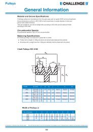
BACKLASH FREE <strong>TORQUE</strong> LIMITER<br />
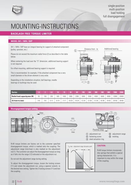
MODEL SK1 / SKN / SKP<br />
SK1 / SKN / SKP have an integral bearing for support of attached component<br />
(pulley, sprocket, etc.)<br />
Please do not exceed the maximum radial force (2) as described in the table<br />
below.<br />
When centering the load over the “S” dimension, additional bearing support<br />
is not required.<br />
For offset mounting, additional bearing support is required.<br />
This is recommended, for example, if the attached component has a very<br />
small diameter or the driven element is very wide.<br />
Depending on the installation situation, ball bearings, needle<br />
bearings or bushings may be used.<br />
Distance from - to<br />
Additional bearing<br />
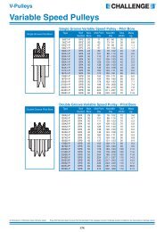
Series 1,5 2 4,5 10 15 30 60 150 200 300 500 800 1500 2500<br />
Radial load capacity,max (N) 50 100 200 500 1400 1800 2300 3000 3500 4500 5600 8000 12000 20000<br />
(S) from-to (mm) 3-6 5-8 5-11 6-14 7-17 10-24 10-24 12-24 12-26 12-28 16-38 16-42 20-50 28-60<br />
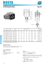
Disengagement torque setting<br />
View<br />
min.<br />
M min 40 Nm M max<br />
max.<br />
Positive stop<br />
adjustment nut<br />
fastening screw<br />
steel actuation ring<br />
adjustment range<br />
marking<br />
R+W torque limiters are factory set to the customer specified<br />
disengagement torque, which is marked onto the coupling. The<br />
adjustment range (min/max) is also marked on the adjustment<br />
nut (1). The customer can adjust the disengagement torque as long<br />
as it falls into the range (12) indicated on the adjustment nut.<br />
Do not exit the adjustment range during setting.<br />
To adjust the disengagement torque, loosen the locking screws<br />
(11) and rotate the adjustment nut, using a spanner wrench, to<br />
the desired new setting. Tighten the 3 locking screws (11) and test<br />
the coupling.<br />
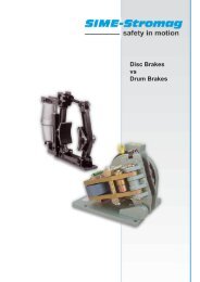
spring force<br />
T KN max<br />
adjustment range Actuation path<br />
T KN min<br />
spring path<br />
CAUTION:<br />
R+W torque limiters incorporate<br />
disc springs that exhibit a special<br />
spring characteristic. It is<br />
important to stay within the range<br />
of the coupling.<br />
22<br />
R+W<br />
www.rwcouplings.com