TORQUE LIMITERS
TORQUE LIMITERS
TORQUE LIMITERS

Create successful ePaper yourself
Turn your PDF publications into a flip-book with our unique Google optimized e-Paper software.
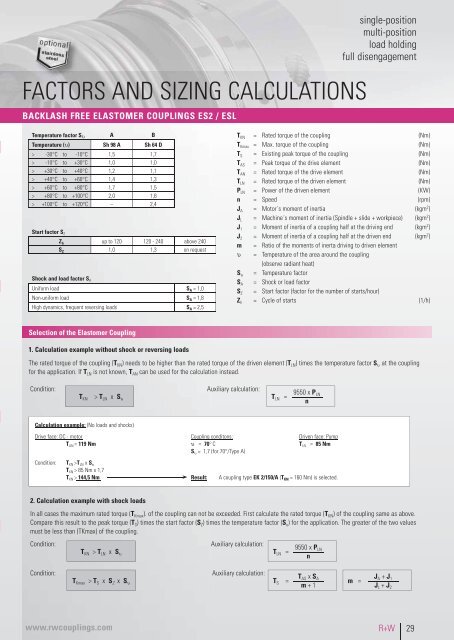
FACTORS AND SIZING CALCULATIONS<br />
BACKLASH FREE ELASTOMER COUPLINGS ES2 / ESL<br />
single-position<br />
multi-position<br />
load holding<br />
full disengagement<br />
Temperature factor S υ A B<br />
Temperature (υ) Sh 98 A Sh 64 D<br />
> -30°C to -10°C 1,5 1,7<br />
> -10°C to +30°C 1,0 1,0<br />
> +30°C to +40°C 1,2 1,1<br />
> +40°C to +60°C 1,4 1,3<br />
> +60°C to +80°C 1,7 1,5<br />
> +80°C to +100°C 2,0 1,8<br />
> +100°C to +120°C – 2,4<br />
Start factor S Z<br />
Z h up to 120 120 - 240 above 240<br />
S Z 1,0 1,3 on request<br />
Shock and load factor S A<br />
Uniform load S A = 1,0<br />
Non-uniform load S A = 1,8<br />
High dynamics, frequent reversing loads S A = 2,5<br />
T KN = Rated torque of the coupling (Nm)<br />
T Kmax = Max. torque of the coupling (Nm)<br />
T S = Existing peak torque of the coupling (Nm)<br />
T AS = Peak torque of the drive element (Nm)<br />
T AN = Rated torque of the drive element (Nm)<br />
T LN = Rated torque of the driven element (Nm)<br />
P LN = Power of the driven element (KW)<br />
n = Speed (rpm)<br />
J A = Motor´s moment of inertia (kgm 2 )<br />
J L = Machine´s moment of inertia (Spindle + slide + workpiece) (kgm 2 )<br />
J 1 = Moment of inertia of a coupling half at the driving end (kgm 2 )<br />
J 2 = Moment of inertia of a coupling half at the driven end (kgm 2 )<br />
m = Ratio of the moments of inerta driving to driven element<br />
υ = Temperature of the area around the coupling<br />
(observe radiant heat)<br />
S υ = Temperature factor<br />
S A = Shock or load factor<br />
S Z = Start factor (factor for the number of starts/hour)<br />
Z h = Cycle of starts (1/h)<br />
Selection of the Elastomer Coupling<br />
1. Calculation example without shock or reversing loads<br />
The rated torque of the coupling (T KN ) needs to be higher than the rated torque of the driven element (T LN ) times the temperature factor S υ at the coupling<br />
for the application. If T LN is not known, T AN can be used for the calculation instead.<br />
Condition:<br />
T KN<br />
> T LN x S υ<br />
Auxiliary calculation:<br />
T LN =<br />
9550 x P LN<br />
n<br />
Calculation example: (No loads and shocks)<br />
Drive face: DC - motor Coupling conditons: Driven face: Pump<br />
T AN = 119 Nm υ = 70° C T LN = 85 Nm<br />
S υ = 1,7 (for 70°/Type A)<br />
Condition:<br />
T KN >T LN x S υ<br />
T KN > 85 Nm x 1,7<br />
T KN > 144,5 Nm Result: A coupling type EK 2/150/A (T KN = 160 Nm) is selected.<br />
2. Calculation example with shock loads<br />
In all cases the maximum rated torque (T Kmax ). of the coupling can not be exceeded. First calculate the rated torque (T KN ) of the coupling same as above.<br />
Compare this result to the peak torque (T S ) times the start factor (S Z ) times the temperature factor (S u ) for the application. The greater of the two values<br />
must be less than (TKmax) of the coupling.<br />
Condition:<br />
T KN > T LN x S υ<br />
Auxiliary calculation:<br />
T LN =<br />
9550 x P LN<br />
n<br />
Condition:<br />
T Kmax > T S x S Z x S υ<br />
Auxiliary calculation:<br />
T S =<br />
T AS x S A<br />
m + 1<br />
m =<br />
J A + J 1<br />
J L + J 2<br />
www.rwcouplings.com<br />
R+W<br />
29