TORQUE LIMITERS
TORQUE LIMITERS
TORQUE LIMITERS

You also want an ePaper? Increase the reach of your titles
YUMPU automatically turns print PDFs into web optimized ePapers that Google loves.
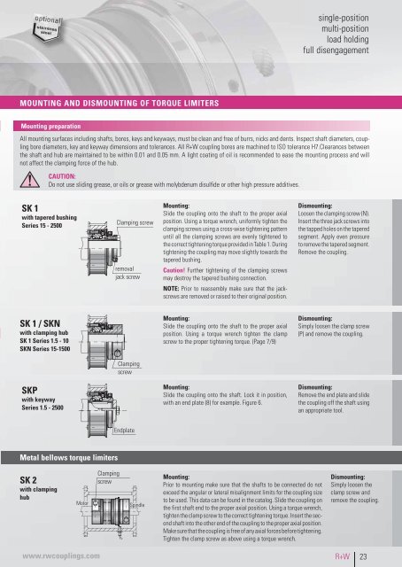
single-position<br />
multi-position<br />
load holding<br />
full disengagement<br />
MOUNTING AND DISMOUNTING OF <strong>TORQUE</strong> <strong>LIMITERS</strong><br />
Mounting preparation<br />
All mounting surfaces including shafts, bores, keys and keyways, must be clean and free of burrs, nicks and dents. Inspect shaft diameters, coupling<br />
bore diameters, key and keyway dimensions and tolerances. All R+W coupling bores are machined to ISO tolerance H7.Clearances between<br />
the shaft and hub are maintained to be within 0.01 and 0.05 mm. A light coating of oil is recommended to ease the mounting process and will<br />
not affect the clamping force of the hub.<br />
CAUTION:<br />
Do not use sliding grease, or oils or grease with molybdenum disulfide or other high pressure additives.<br />
SK 1<br />
with tapered bushing<br />
Series 15 - 2500<br />
Clamping screw<br />
removal<br />
jack screw<br />
Mounting:<br />
Slide the coupling onto the shaft to the proper axial<br />
position. Using a torque wrench, uniformly tighten the<br />
clamping screws using a cross-wise tightening pattern<br />
until all the clamping screws are evenly tightened to<br />
the correct tightening torque provided in Table 1. During<br />
tightening the coupling may move slightly towards the<br />
tapered bushing.<br />
Caution! Further tightening of the clamping screws<br />
may destroy the tapered bushing connection.<br />
NOTE: Prior to reassembly make sure that the jackscrews<br />
are removed or raised to their original position.<br />
Dismounting:<br />
Loosen the clamping screw (N).<br />
Insert the three jack screws into<br />
the tapped holes on the tapered<br />
segment. Apply even pressure<br />
to remove the tapered segment.<br />
Remove the coupling.<br />
SK 1 / SKN<br />
with clamping hub<br />
SK 1 Series 1.5 - 10<br />
SKN Series 15-1500<br />
Mounting:<br />
Slide the coupling onto the shaft to the proper axial<br />
position. Using a torque wrench tighten the clamp<br />
screw to the proper tightening torque. (Page 7/9)<br />
Dismounting:<br />
Simply loosen the clamp screw<br />
(P) and remove the coupling.<br />
Clamping<br />
screw<br />
SKP<br />
with keyway<br />
Series 1.5 - 2500<br />
Mounting:<br />
Slide the coupling onto the shaft. Lock it in position,<br />
with an end plate (8) for example. Figure 6.<br />
Dismounting:<br />
Remove the end plate and slide<br />
the coupling off the shaft using<br />
an appropriate tool.<br />
Endplate<br />
Metal bellows torque limiters<br />
SK 2<br />
with clamping<br />
hub<br />
Motor<br />
Clamping<br />
screw<br />
Spindle<br />
Mounting:<br />
Prior to mounting make sure that the shafts to be connected do not<br />
exceed the angular or lateral misalignment limits for the coupling size<br />
to be used. This data can be found in the catalog. Slide the coupling on<br />
the first shaft end to the proper axial position. Using a torque wrench,<br />
tighten the clamp screw to the correct tightening torque. Insert the second<br />
shaft into the other end of the coupling to the proper axial position.<br />
Make sure that the coupling is free of any axial forces before tightening.<br />
Tighten the clamp screw as above using a torque wrench.<br />
Dismounting:<br />
Simply loosen the<br />
clamp screw and<br />
remove the coupling.<br />
www.rwcouplings.com<br />
R+W 23