ROSTA RUBBER SUSPENSION UNITS
ROSTA RUBBER SUSPENSION UNITS
ROSTA RUBBER SUSPENSION UNITS

Create successful ePaper yourself
Turn your PDF publications into a flip-book with our unique Google optimized e-Paper software.
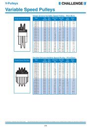
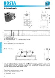
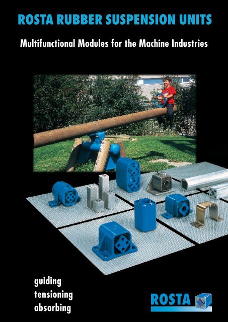
<strong>ROSTA</strong> <strong>RUBBER</strong> <strong>SUSPENSION</strong> <strong>UNITS</strong><br />
Multifunctional Modules for the Machine Industries<br />
guiding<br />
tensioning<br />
absorbing<br />
<strong>ROSTA</strong>
<strong>ROSTA</strong><br />
Product Range “Modules”<br />
<strong>ROSTA</strong> Rubber Suspension Unit<br />
Type DR-S Page 19<br />
Rubber Suspension Units<br />
Housing made out of steel, inner square section made out<br />
of steel tube for mounting “plug-in” lever arms on one or<br />
both sides. The inserted part should be at least three times<br />
longer than the clearance “C”. Up to type DR-S 18 the lever<br />
arms can be mounted by one through-bolt and the levers<br />
are then fixed by frictional force at any position within<br />
360°. Both ways of fixation are particularly well suited for<br />
motions at the plus or minus angular range (no alternating<br />
motions across the neutral axis = play). All metal parts are<br />
paint-finished.<br />
<strong>ROSTA</strong> Rubber Suspension Unit<br />
Type DR-A/C Pages 20/21<br />
Steel housing with inner square section made of light alloy<br />
with four small bores or one big through bore. Levers can<br />
be mounted on one or on both sides by means of bolts.<br />
Type DR-A with two or four through bores, especially constructed<br />
for transmitting alternating motions by passing the<br />
neutral axis in either direction. Type DR-C with central<br />
bore. The frictional force of this type assures a safe fixation<br />
of the lever arms in any position. All metal parts are paintfinished.<br />
<strong>ROSTA</strong> Rubber Suspension Unit<br />
Type DK-S Page 22<br />
Round housing made of light alloy profile, inner square<br />
section made out of steel tube, the “plug-in” lever arms can<br />
be mounted on one or both sides. The inserted part should<br />
be at least three times longer than the clearance “C”. This<br />
kind of connection is particularly well suited for angular<br />
motions at the plus or minus range (no alternating motions<br />
across the neutral axis = play). All metal parts are paintfinished.<br />
<strong>ROSTA</strong> Rubber Suspension Unit<br />
Type DK-A Page 23<br />
Round housing and inner square section made of light<br />
alloy profiles, inner square section with four “throughbores”,<br />
the lever arms can be bolted on and, if necessary,<br />
the bores can be tapped, too. Both ways provide an excellent<br />
connection without play which is necessary in order to<br />
transmit alternating motions by passing the neutral position<br />
in either direction. All metal parts are paint-finished.<br />
16
<strong>ROSTA</strong><br />
Product Range<br />
<strong>ROSTA</strong> Rubber Suspension Unit<br />
Type DO-S Page 24<br />
Housing up to size 45 made out of light alloy profile, size 50<br />
made out of spheroidal graphite cast iron, inner square<br />
section made out of steel, the “plug-in” lever arms are to<br />
be attached on one or both sides. Please note, the inserted<br />
length should be at least three times longer than the clearance<br />
“C”. Up to size DO-S 18 the lever arms can also be<br />
mounted by one “through-bolt”, the levers are held by the<br />
resulting frictional force. Thereby, the positioning of the<br />
levers at any position within 360° is admissible. Both ways<br />
are particularly well suited for alternating motions at the<br />
plus or minus angular range. All metal parts are paintfinished.<br />
Rubber Suspension Units<br />
<strong>ROSTA</strong> Rubber Suspension Unit<br />
Type DO-A Page 25<br />
Housing up to size 45 made out of light alloy profile, size 50<br />
made out of spheroidal graphite cast iron, inner square<br />
section made out of light alloy profile with four “throughbores”.<br />
The levers can be mounted on one or both sides by<br />
means of bolts. It provides an excellent attachment without<br />
play which is most important in order to transmit alternating<br />
motions by passing the neutral axis in either direction.<br />
All metal parts are paint-finished.<br />
<strong>ROSTA</strong> Rubber Suspension Unit<br />
Type DW-A Page 26<br />
Housing with welded-on brackets and inner square section<br />
made out of steel, inner square section with four threaded<br />
holes on both sides, suitable for mounting lever arms and<br />
attachments clearance-free. The unit has to be bolted on<br />
machine part through the welded-on brackets. These units<br />
are designed to transmit alternating motions which occur in<br />
either direction, by passing the neutral position. All metal<br />
parts are paint-finished.<br />
17
<strong>ROSTA</strong><br />
Product Range<br />
<strong>ROSTA</strong> modules should be connected on machine<br />
parts/structures by means of the standardized<br />
clamps and brackets. Relevant welded connections<br />
would affect (overheat) the rubber inserts<br />
and damage the entire suspension device!<br />
Rubber Suspension Units<br />
<strong>ROSTA</strong> Clamp Type BR Page 27<br />
(fitting all DR-elements)<br />
The clamps are supplied separately without bolts. They are<br />
standardized to fit exactly for the fixation and positioning<br />
of the <strong>ROSTA</strong> rubber suspension units type DR-S, DR-A and<br />
DR-C without any welding. For longer units two or more<br />
clamps are recommended. The clamps are paint-finished.<br />
<strong>ROSTA</strong> Clamp Type BK Page 27<br />
(fitting all DK-elements)<br />
The clamps are supplied separately without bolts. They are<br />
standardized to fit exactly for the fixation and positioning<br />
of the <strong>ROSTA</strong> rubber suspension units type DK-S and DK-A<br />
by frictional force created by the bolted double clamp. For<br />
longer units two or more clamps are recommended. All<br />
clamps are paint-finished.<br />
<strong>ROSTA</strong> Bracket Type WS Page 27<br />
This multi-purpose brackets make an easy screw connection<br />
possible on the inner squares of the <strong>ROSTA</strong> rubber<br />
suspension units type DR-A, DK-A and DO-A (as well as a<br />
housing fixation of the tensioner devices type SE). The base<br />
of the angle section can be positioned in both directions<br />
and offers together with the different clamps many combination<br />
possibilities of the element assembling. The brackets<br />
are paint-finished.<br />
18
<strong>ROSTA</strong><br />
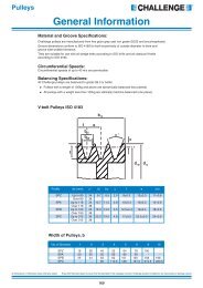
Rubber Suspension Unit<br />
Type DR-S<br />
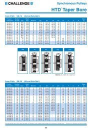
Torque M in Nm at ) <br />
Weight<br />
Art. No. Type L L1 0<br />
– 0.3 C* D** S 5° 10° 15° 20° 25° 30° in kg<br />
01 021 001 DR-S 11 x 20 20 25 8 + 0.25<br />
0 20 +0.1<br />
– 0.2 11 0.3 0.8 1.3 2.0 2.9 4.0 0.04<br />
01 021 002 DR-S 11 x 30 30 35 8 + 0.25<br />
0 20 +0.1<br />
– 0.2 11 0.4 1.2 2.0 3.1 4.3 6.0 0.05<br />
01 021 003 DR-S 11 x 50 50 55 8 + 0.25<br />
0 20 +0.1<br />
– 0.2 11 0.7 2.0 3.4 5.1 7.2 10.0 0.08<br />
Rubber Suspension Units<br />
01 021 004 DR-S 15 x 25 25 30 11 + 0 0.25<br />
27 +0.2<br />
– 0.1 15 0.7 1.6 2.6 4.0 5.7 8.2 0.07<br />
01 021 005 DR-S 15 x 40 40 45 11 + 0 0.25<br />
27 +0.2<br />
– 0.1 15 1.1 2.5 4.2 6.4 9.2 13.2 0.12<br />
01 021 006 DR-S 15 x 60 60 65 11 + 0 0.25<br />
27 +0.2<br />
– 0.1 15 1.6 3.8 6.3 9.6 13.8 19.8 0.18<br />
01 021 007 DR-S 18 x 30 30 35 12 + 0.25<br />
0 32 +0.1<br />
– 0.2 18 1.9 4.5 7.5 11.0 15.0 20.6 0.12<br />
01 021 008 DR-S 18 x 50 50 55 12 + 0.25<br />
0 32 +0.1<br />
– 0.2 18 3.2 7.5 12.5 18.3 25.0 34.4 0.20<br />
01 021 009 DR-S 18 x 80 80 85 12 + 0.25<br />
0 32 +0.1<br />
– 0.2 18 5.1 12.0 20.0 29.3 40.0 55.0 0.32<br />
01 021 010 DR-S 27 x 40 40 45 22 + 0.25<br />
0 45 +0.2<br />
– 0.1 27 4.7 10.7 17.5 26.9 39.5 57.0 0.26<br />
01 021 011 DR-S 27 x 60 60 65 22 + 0.25<br />
0 45 +0.2<br />
– 0.1 27 7.0 16.0 26.3 40.3 59.3 85.5 0.39<br />
01 021 012 DR-S 27 x 100 100 105 22 + 0.25<br />
0 45 +0.2<br />
– 0.1 27 11.7 26.7 43.8 67.2 98.8 142.5 0.65<br />
01 021 013 DR-S 38 x 60 60 70 30 + 0 0.25<br />
60 + – 0.15<br />
0.3 38 13.0 30.4 50.6 78.0 113.0 162.0 0.67<br />
01 021 014 DR-S 38 x 80 80 90 30 + 0 0.25<br />
60 + – 0.15<br />
0.3 38 17.3 40.5 67.5 104.0 151.0 216.0 0.90<br />
01 021 015 DR-S 38 x 120 120 130 30 + 0 0.25<br />
60 + – 0.15<br />
0.3 38 26.0 60.8 101.2 156.0 226.0 324.0 1.32<br />
01 021 016 DR-S 45 x 80 80 90 35 + 0 0.25<br />
72 + – 0.15<br />
0.3 45 27.6 62.4 104.0 160.0 222.0 320.0 1.17<br />
01 021 017 DR-S 45 x 100 100 110 35 + 0 0.25<br />
72 + – 0.15<br />
0.3 45 34.5 78.0 130.0 200.0 278.0 400.0 1.45<br />
01 021 018 DR-S 45 x 150 150 160 35 + 0 0.25<br />
72 + – 0.15<br />
0.3 45 51.8 117.0 195.0 300.0 420.0 600.0 2.15<br />
01 021 019 DR-S 50 x 120 120 130 40 + 0 0.25<br />
78 + – 0.15<br />
0.3 50 51.0 133.0 250.0 395.0 570.0 780.0 2.10<br />
01 021 020 DR-S 50 x 200 200 210 40 + 0 0.25<br />
78 + – 0.15<br />
0.3 50 102.0 260.0 475.0 745.0 1070.0 1450.0 3.46<br />
01 021 021 DR-S 50 x 300 300 310 40 + 0.25<br />
0 78 + 0.15<br />
– 0.3 50 150.0 385.0 700.0 1100.0 1590.0 2160.0 5.12<br />
Plug-in Connections<br />
An easy and cost-effective connecting variant, if the unit is<br />
under pretension and acts in only one direction. Alternating<br />
oscillations in both directions would cause noise due<br />
to play compensation.<br />
“inserted<br />
lever core”<br />
“outer square<br />
plug-in connection”<br />
**<br />
**<br />
“inserted lever core”:<br />
The connection square has to be of polished quality with<br />
tolerance from h 9 to 11. According to the specific connection,<br />
edge radius the squares might have to be machined.<br />
“outer square plug-in connection”:<br />
The tolerance of the outer housing corresponds to commercial<br />
square tubes. The thickness of the additional protection<br />
paint of 40 to 80 µm has to be taken in consideration.<br />
19
<strong>ROSTA</strong><br />
Rubber Suspension Unit<br />
Type DR-A<br />
Rubber Suspension Units<br />
Ø 20 +0.5<br />
0 (Type DR-A 50)<br />
Torque M in Nm at ) <br />
Weight<br />
Art. No. Type L L1 0<br />
– 0.3 A +0.5<br />
0.3 B D S 5° 10° 15° 20° 25° 30° in kg<br />
01 011 001 DR-A 15 x 25 25 30 5 10 ± 0.2 27 +0.2<br />
– 0.1 15 0.7 1.6 2.6 4.0 5.7 8.2 0.06<br />
01 011 002 DR-A 15 x 40 40 45 5 10 ± 0.2 27 +0.2<br />
– 0.1 15 1.1 2.5 4.2 6.4 9.2 13.2 0.10<br />
01 011 003 DR-A 15 x 60 60 65 5 10 ± 0.2 27 +0.2<br />
– 0.1 15 1.6 3.8 6.3 9.6 13.8 19.8 0.15<br />
01 011 004 DR-A 18 x 30 30 35 6 12 ± 0.3 32 +0.1<br />
– 0.2 18 1.9 4.5 7.5 11.0 15.0 20.6 0.10<br />
01 011 005 DR-A 18 x 50 50 55 6 12 ± 0.3 32 +0.1<br />
– 0.2 18 3.2 7.5 12.5 18.3 25.0 34.4 0.16<br />
01 011 006 DR-A 18 x 80 80 85 6 12 ± 0.3 32 +0.1<br />
– 0.2 18 5.1 12.0 20.0 29.3 40.0 55.0 0.25<br />
01 011 007 DR-A 27 x 40 40 45 8 20 ± 0.4 45 +0.2<br />
– 0.1 27 4.7 10.7 17.5 26.9 39.5 57.0 0.25<br />
01 011 008 DR-A 27 x 60 60 65 8 20 ± 0.4 45 +0.2<br />
– 0.1 27 7.0 16.0 26.3 40.3 59.3 85.5 0.36<br />
01 011 009 DR-A 27 x 100 100 105 8 20 ± 0.4 45 +0.2<br />
– 0.1 27 11.7 26.7 43.8 67.2 98.8 142.5 0.60<br />
01 011 010 DR-A 38 x 60 60 70 10 25 ± 0.4 60 + – 0.15<br />
0.3 38 13.0 30.4 50.6 78.0 113.0 162.0 0.60<br />
01 011 011 DR-A 38 x 80 80 90 10 25 ± 0.4 60 + – 0.15<br />
0.3 38 17.3 40.5 67.5 104.0 151.0 216.0 0.79<br />
01 011 012 DR-A 38 x 120 120 130 10 25 ± 0.4 60 + – 0.15<br />
0.3 38 26.0 60.8 101.2 156.0 226.0 324.0 1.16<br />
01 011 013 DR-A 45 x 80 80 90 12 35 ± 0.5 72 + – 0.15<br />
0.3 45 27.6 62.4 104.0 160.0 222.0 320.0 1.00<br />
01 011 014 DR-A 45 x 100 100 110 12 35 ± 0.5 72 + – 0.15<br />
0.3 45 34.5 78.0 130.0 200.0 278.0 400.0 1.22<br />
01 011 015 DR-A 45 x 150 150 160 12 35 ± 0.5 72 + – 0.15<br />
0.3 45 51.8 117.0 195.0 300.0 420.0 600.0 1.83<br />
01 011 016 DR-A 50 x 120 120 130 M12 x 40 40 ± 0.5 78 + – 0.15<br />
0.3 50 51.0 133.0 250.0 395.0 570.0 780.0 1.80<br />
01 011 017 DR-A 50 x 200 200 210 M12 x 40 40 ± 0.5 78 + – 0.15<br />
0.3 50 102.0 260.0 475.0 745.0 1070.0 1450.0 3.00<br />
01 011 018 DR-A 50 x 300 300 310 M12 x 40 40 ± 0.5 78 + 0.15<br />
– 0.3 50 150.0 385.0 700.0 1100.0 1590.0 2160.0 4.47<br />
Bolted Lever Arm on Inner Square<br />
Connection by means of 2 or 4 shaft screws across the inner<br />
square profile; or by means of set screws directly on the<br />
square profile (the customer-side thread taping is required).<br />
20
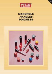
<strong>ROSTA</strong><br />
Rubber Suspension Unit<br />
Type DR-C<br />
Torque M in Nm at ) <br />
Weight<br />
Art. No. Type L L1 0<br />
– 0.3 A D S 5° 10° 15° 20° 25° 30° in kg<br />
01 031 010 DR-C 15 x 25 25 30 10 +0.4<br />
+ 0.2 27 +0.2<br />
– 0.1 15 0.7 1.6 2.6 4.0 5.7 8.2 0.06<br />
01 031 011 DR-C 15 x 40 40 45 10 +0.4<br />
+ 0.2 27 +0.2<br />
– 0.1 15 1.1 2.5 4.2 6.4 9.2 13.2 0.10<br />
01 031 012 DR-C 15 x 60 60 65 10 +0.4<br />
+ 0.2 27 +0.2<br />
– 0.1 15 1.6 3.8 6.3 9.6 13.8 19.8 0.15<br />
Rubber Suspension Units<br />
01 031 001 DR-C 18 x 30 30 35 13 – – 0.2 0.2<br />
32 +0.1<br />
– 0.2 18 1.9 4.5 7.5 11.0 15.0 20.6 0.10<br />
01 031 002 DR-C 18 x 50 50 55 13 – – 0.2 0.2<br />
32 +0.1<br />
– 0.2 18 3.2 7.5 12.5 18.3 25.0 34.4 0.16<br />
01 031 003 DR-C 18 x 80 80 85 13 – – 0.2 0.2<br />
32 +0.1<br />
– 0.2 18 5.1 12.0 20.0 29.3 40.0 55.0 0.25<br />
01 031 004 DR-C 27 x 40 40 45 16 +0.5<br />
+ 0.3 45 +0.2<br />
– 0.1 27 4.7 10.7 17.5 26.9 39.5 57.0 0.25<br />
01 031 005 DR-C 27 x 60 60 65 16 +0.5<br />
+ 0.3 45 +0.2<br />
– 0.1 27 7.0 16.0 26.3 40.3 59.3 85.5 0.36<br />
01 031 006 DR-C 27 x 100 100 105 16 +0.5<br />
+ 0.3 45 +0.2<br />
– 0.1 27 11.7 26.7 43.8 67.2 98.8 142.5 0.60<br />
01 031 007 DR-C 38 x 60 60 70 20 +0.5<br />
+ 0.2 60 + – 0.15<br />
0.3 38 13.0 30.4 50.6 78.0 113.0 162.0 0.60<br />
01 031 008 DR-C 38 x 80 80 90 20 +0.5<br />
+ 0.2 60 + – 0.15<br />
0.3 38 17.3 40.5 67.5 104.0 151.0 216.0 0.79<br />
01 031 009 DR-C 38 x 120 120 130 20 +0.5<br />
+ 0.2 60 + – 0.15<br />
0.3 38 26.0 60.8 101.2 156.0 226.0 324.0 1.16<br />
01 031 013 DR-C 45 x 80 80 90 24 +0.5<br />
+ 0.2 72 + – 0.15<br />
0.3 45 27.6 62.4 104.0 160.0 222.0 320.0 1.00<br />
01 031 014 DR-C 45 x 100 100 110 24 +0.5<br />
+ 0.2 72 + – 0.15<br />
0.3 45 34.5 78.0 130.0 200.0 278.0 400.0 1.22<br />
01 031 015 DR-C 50 x 120 120 130 30 +0.5<br />
+ 0.2 78 + 0.15<br />
– 0.3 50 51.0 133.0 250.0 395.0 570.0 780.0 1.80<br />
01 031 016 DR-C 50 x 200 200 210 30 +0.5<br />
+ 0.2 78 + 0.15<br />
– 0.3 50 102.0 260.0 475.0 745.0 1070.0 1450.0 3.00<br />
Bolted Lever Arm on Inner Square<br />
Positioning of the lever arm by means of central shaft screw<br />
and resulting frictional connection. Ideal for continuous<br />
positioning of the lever arm.<br />
This connection should not be applied at alternating oscillations<br />
by big angular motions ( ±10°).<br />
In order to get the most best frictional connection, the paint<br />
cover on the core front should be removed prior bolting<br />
any connection part.<br />
21
<strong>ROSTA</strong><br />
Rubber Suspension Unit<br />
Type DK-S<br />
Rubber Suspension Units<br />
Torque M in Nm at ) <br />
Weight<br />
Art. No. Type L L1 0<br />
– 0.3 C* D** E F S 5° 10° 15° 20° 25° 30° in kg<br />
01 081 001 DK-S 11 x 20 20 25 8 + + 0.25<br />
0.25 28 +0.3<br />
– 0.1 4 2.5 11 0.3 0.8 1.3 2.0 2.9 4.0 0.03<br />
01 081 002 DK-S 11 x 30 30 35 8 + + 0.25<br />
0.25 28 +0.3<br />
– 0.1 4 2.5 11 0.4 1.2 2.0 3.1 4.3 6.0 0.05<br />
01 081 003 DK-S 11 x 50 50 55 8 + + 0.25<br />
0.25 28 +0.3<br />
– 0.1 4 2.5 11 0.7 2.0 3.4 5.1 7.2 10.0 0.07<br />
01 081 004 DK-S 15 x 25 25 30 11 + + 0.25<br />
0.25 36 +0.3<br />
– 0.1 5 2.5 15 0.7 1.6 2.6 4.0 5.7 8.2 0.06<br />
01 081 005 DK-S 15 x 40 40 45 11 + + 0.25<br />
0.25 36 +0.3<br />
– 0.1 5 2.5 15 1.1 2.5 4.2 6.4 9.2 13.2 0.10<br />
01 081 006 DK-S 15 x 60 60 65 11 + + 0.25<br />
0.25 36 +0.3<br />
– 0.1 5 2.5 15 1.6 3.8 6.3 9.6 13.8 19.8 0.14<br />
01 081 007 DK-S 18 x 30 30 35 12 + + 0.25<br />
0.25 45 +0.4<br />
– 0.1 5 2.5 18 1.9 4.5 7.5 11.0 15.0 20.6 0.13<br />
01 081 008 DK-S 18 x 50 50 55 12 + + 0.25<br />
0.25 45 +0.4<br />
– 0.1 5 2.5 18 3.2 7.5 12.5 18.3 25.0 34.4 0.20<br />
01 081 009 DK-S 18 x 80 80 85 12 + + 0.25<br />
0.25 45 +0.4<br />
– 0.1 5 2.5 18 5.1 12.0 20.0 29.3 40.0 55.0 0.33<br />
01 081 010 DK-S 27 x 40 40 45 22 + + 0.25<br />
0.25 62 +0.5<br />
– 0.1 6 3.5 27 4.7 10.7 17.5 26.9 39.5 57.0 0.27<br />
01 081 011 DK-S 27 x 60 60 65 22 + + 0.25<br />
0.25 62 +0.5<br />
– 0.1 6 3.5 27 7.0 16.0 26.3 40.3 59.3 85.5 0.40<br />
01 081 012 DK-S 27 x 100 100 105 22 + + 0.25<br />
0.25 62 +0.5<br />
– 0.1 6 3.5 27 11.7 26.7 43.8 67.2 98.8 142.5 0.66<br />
01 081 013 DK-S 38 x 60 60 70 30 + + 0.25<br />
0.25 80 +0.6<br />
– 0.1 7 3.5 38 13.0 30.4 50.6 78.0 113.0 162.0 0.72<br />
01 081 014 DK-S 38 x 80 80 90 30 + + 0.25<br />
0.25 80 +0.6<br />
– 0.1 7 3.5 38 17.3 40.5 67.5 104.0 151.0 216.0 0.94<br />
01 081 015 DK-S 38 x 120 120 130 30 + + 0.25<br />
0.25 80 +0.6<br />
– 0.1 7 3.5 38 26.0 60.8 101.2 156.0 226.0 324.0 1.37<br />
01 081 016 DK-S 45 x 80 80 90 35 + + 0.25<br />
0.25 95 +0.8<br />
– 0.1 8 4.5 45 27.6 62.4 104.0 160.0 222.0 320.0 1.35<br />
01 081 017 DK-S 45 x 100 100 110 35 + + 0.25<br />
0.25 95 +0.8<br />
– 0.1 8 4.5 45 34.5 78.0 130.0 200.0 278.0 400.0 1.65<br />
01 081 018 DK-S 45 x 150 150 160 35 + + 0.25<br />
0.25 95 +0.8<br />
– 0.1 8 4.5 45 51.8 117.0 195.0 300.0 420.0 600.0 2.44<br />
01 081 019 DK-S 50 x 120 120 130 40 + + 0.25<br />
0.25 108 +1.0<br />
+ 0.1 8 4.5 50 51.0 133.0 250.0 395.0 570.0 780.0 2.55<br />
01 081 020 DK-S 50 x 200 200 210 40 + + 0.25<br />
0.25 108 +1.0<br />
+ 0.1 8 4.5 50 102.0 260.0 475.0 745.0 1070.0 1450.0 4.21<br />
01 081 021 DK-S 50 x 300 300 310 40 + 0.25<br />
+ 0.25 108 +1.0<br />
+ 0.1 8 4.5 50 150.0 385.0 700.0 1100.0 1590.0 2160.0 6.45<br />
* Plug-in connection “inserted” see page 19.<br />
** Frictional “Fist” Connection on Outer Housing<br />
The round outer housing can be either positioned by means<br />
of a clamping jaw or inserted into a “fist”-bracket. The<br />
tolerances of the outer housing diameter as well as the<br />
thickness of the protection paint (40 to 80 µm) have to be<br />
taken in consideration.<br />
22
<strong>ROSTA</strong><br />
Rubber Suspension Unit<br />
Type DK-A<br />
Ø 20 +0.5<br />
0 (Type DK-A 50)<br />
Torque M in Nm at ) <br />
Weight<br />
Art. No. Type L L1 0<br />
– 0.3 A +0.5<br />
+ 0.5 B D E F S 5° 10° 15° 20° 25° 30° in kg<br />
01 071 001 DK-A 15 x 25 25 30 5 10 ± 0.2 36 +0.3<br />
– 0.1 5 2.5 15 0.7 1.6 2.6 4.0 5.7 8.2 0.05<br />
01 071 002 DK-A 15 x 40 40 45 5 10 ± 0.2 36 +0.3<br />
– 0.1 5 2.5 15 1.1 2.5 4.2 6.4 9.2 13.2 0.08<br />
01 071 003 DK-A 15 x 60 60 65 5 10 ± 0.2 36 +0.3<br />
– 0.1 5 2.5 15 1.6 3.8 6.3 9.6 13.8 19.8 0.12<br />
Rubber Suspension Units<br />
01 071 004 DK-A 18 x 30 30 35 6 12 ± 0.3 45 +0.4<br />
– 0.1 5 2.5 18 1.9 4.5 7.5 11.0 15.0 20.6 0.10<br />
01 071 005 DK-A 18 x 50 50 55 6 12 ± 0.3 45 +0.4<br />
– 0.1 5 2.5 18 3.2 7.5 12.5 18.3 25.0 34.4 0.16<br />
01 071 006 DK-A 18 x 80 80 85 6 12 ± 0.3 45 +0.4<br />
– 0.1 5 2.5 18 5.1 12.0 20.0 29.3 40.0 55.0 0.26<br />
01 071 007 DK-A 27 x 40 40 45 8 20 ± 0.4 62 +0.5<br />
– 0.1 6 3.0 27 4.7 10.7 17.5 26.9 39.5 57.0 0.25<br />
01 071 008 DK-A 27 x 60 60 65 8 20 ± 0.4 62 +0.5<br />
– 0.1 6 3.0 27 7.0 16.0 26.3 40.3 59.3 85.5 0.37<br />
01 071 009 DK-A 27 x 100 100 105 8 20 ± 0.4 62 +0.5<br />
– 0.1 6 3.0 27 11.7 26.7 43.8 67.2 98.8 142.5 0.62<br />
01 071 010 DK-A 38 x 60 60 70 10 25 ± 0.4 80 +0.6<br />
– 0.1 7 3.5 38 13.0 30.4 50.6 78.0 113.0 162.0 0.63<br />
01 071 011 DK-A 38 x 80 80 90 10 25 ± 0.4 80 +0.6<br />
– 0.1 7 3.5 38 17.3 40.5 67.5 104.0 151.0 216.0 0.83<br />
01 071 012 DK-A 38 x 120 120 130 10 25 ± 0.4 80 +0.6<br />
– 0.1 7 3.5 38 26.0 60.8 101.2 156.0 226.0 324.0 1.22<br />
01 071 013 DK-A 45 x 80 80 90 12 35 ± 0.5 95 +0.8<br />
– 0.1 8 4.0 45 27.6 62.4 104.0 160.0 222.0 320.0 1.15<br />
01 071 014 DK-A 45 x 100 100 110 12 35 ± 0.5 95 +0.8<br />
– 0.1 8 4.0 45 34.5 78.0 130.0 200.0 278.0 400.0 1.44<br />
01 071 015 DK-A 45 x 150 150 160 12 35 ± 0.5 95 +0.8<br />
– 0.1 8 4.0 45 51.8 117.0 195.0 300.0 420.0 600.0 2.12<br />
01 071 016 DK-A 50 x 120 120 130 M12 x 40 40 ± 0.5 108 +1.0<br />
– 0.1 8 4.0 50 51.0 133.0 250.0 395.0 570.0 780.0 2.35<br />
01 071 017 DK-A 50 x 200 200 210 M12 x 40 40 ± 0.5 108 +1.0<br />
– 0.1 8 4.0 50 102.0 260.0 475.0 745.0 1070.0 1460.0 3.75<br />
01 071 018 DK-A 50 x 300 300 310 M12 x 40 40 ± 0.5 108 +1.0<br />
– 0.1 8 4.0 50 150.0 385.0 700.0 1100.0 1590.0 2160.0 5.60<br />
Fixation by Clamp Type BK<br />
The fixation of the outer housing by means of the standardized<br />
clamp type BK makes the continuous and individual<br />
pretension of the unit in both directions easy and adjustable<br />
(clamp type BK on page 27).<br />
23
<strong>ROSTA</strong><br />
Rubber Suspension Unit<br />
Type DO-S<br />
Rubber Suspension Units<br />
Torque M in Nm at ) <br />
Weight<br />
Art. No. Type L L1 0<br />
– 0.3 C D E F S 5° 10° 15° 20° 25° 30° in kg<br />
01 051 001 DO-S 15 x 25 25 30 11 + – 0.1 0.25<br />
28 ±0.15 25.5 53.5 ± 0.2 15 0.7 1.6 2.6 4.0 5.7 8.2 0.10<br />
01 051 002 DO-S 15 x 40 40 45 11 + – 0.1 0.25<br />
28 ±0.15 25.5 53.5 ± 0.2 15 1.1 2.5 4.2 6.4 9.2 13.2 0.14<br />
01 051 003 DO-S 15 x 60 60 65 11 + – 0.1 0.25<br />
28 ±0.15 25.5 53.5 ± 0.2 15 1.6 3.8 6.3 9.6 13.8 19.8 0.21<br />
01 051 004 DO-S 18 x 30 30 35 12 + – 0.1 0.25<br />
34 ±0.15 31.5 65 +0.2<br />
– 0.1 18 1.9 4.5 7.5 11.0 15.0 20.6 0.17<br />
01 051 005 DO-S 18 x 50 50 55 12 + – 0.1 0.25<br />
34 ±0.15 31.5 65 +0.2<br />
– 0.1 18 3.2 7.5 12.5 18.3 25.0 34.4 0.29<br />
01 051 006 DO-S 18 x 80 80 85 12 + – 0.1 0.25<br />
34 ±0.15 31.5 65 +0.2<br />
– 0.1 18 5.1 12.0 20.0 29.3 40.0 55.0 0.45<br />
01 051 007 DO-S 27 x 40 40 45 22 + – 0.1 0.25<br />
47 ±0.15 44.5 91 +0.2<br />
– 0.1 27 4.7 10.7 17.5 26.9 39.5 57.0 0.35<br />
01 051 008 DO-S 27 x 60 60 65 22 + – 0.1 0.25<br />
47 ±0.15 44.5 91 +0.2<br />
– 0.1 27 7.0 16.0 26.3 40.3 59.3 85.5 0.52<br />
01 051 009 DO-S 27 x 100 100 105 22 + – 0.1 0.25<br />
47 ±0.15 44.5 91 +0.2<br />
– 0.1 27 11.7 26.7 43.8 67.2 98.8 142.5 0.86<br />
01 051 010 DO-S 38 x 60 60 70 30 + – 0.1 0.25<br />
63 ±0.20 60.5 123 +0.3<br />
– 0.1 38 13.0 30.4 50.6 78.0 113.0 162.0 1.03<br />
01 051 011 DO-S 38 x 80 80 90 30 + – 0.1 0.25<br />
63 ±0.20 60.5 123 +0.3<br />
– 0.1 38 17.3 40.5 67.5 104.0 151.0 216.0 1.35<br />
01 051 012 DO-S 38 x 120 120 130 30 + – 0.1 0.25<br />
63 ±0.20 60.5 123 +0.3<br />
– 0.1 38 26.0 60.8 101.2 156.0 226.0 324.0 2.00<br />
01 051 013 DO-S 45 x 80 80 90 35 + – 0.1 0.25<br />
85 ±0.15 73.5 149.4 +1.6<br />
– 0.4 45 27.6 62.4 104.0 160.0 222.0 320.0 2.20<br />
01 051 014 DO-S 45 x 100 100 110 35 + – 0.1 0.25<br />
85 ±0.15 73.5 149.4 +1.6<br />
– 0.4 45 34.5 78.0 130.0 200.0 278.0 400.0 2.65<br />
01 051 015 DO-S 45 x 150 150 160 35 + – 0.1 0.25<br />
85 ±0.15 73.5 149.4 +1.6<br />
– 0.4 45 51.8 117.0 195.0 300.0 420.0 600.0 3.96<br />
01 051 016 DO-S 50 x 120 120 130 40 + 0.25<br />
– 0.1 89 ±0.15 78.5 167 50 51.0 133.0 250.0 395.0 570.0 780.0 5.67<br />
* DO-S 45 with convex housing shape<br />
Serial Connection<br />
Arrangements according to fig. I and II offer a doubled<br />
oscillating angle (± 60°) at constant torque of a single unit.<br />
24
<strong>ROSTA</strong><br />
Rubber Suspension Unit<br />
Type DO-A<br />
Only DO-A 50 size<br />
Ø 20 +0.5<br />
0 (Type DO-A 50)<br />
Torque M in Nm at ) Weight<br />
Art. No. Type L L1 0<br />
– 0.3 A +0.5<br />
0 B D E F S 5° 10° 15° 20° 25° 30° in kg<br />
01 041 001 DO-A 15 x 25 25 30 5 10 ± 0.2 28 ±0.15 25.5 53.5 ± 0.2 15 0.7 1.6 2.6 4.0 5.7 8.2 0.07<br />
01 041 002 DO-A 15 x 40 40 45 5 10 ± 0.2 28 ±0.15 25.5 53.5 ± 0.2 15 1.1 2.5 4.2 6.4 9.2 13.2 0.10<br />
01 041 003 DO-A 15 x 60 60 65 5 10 ± 0.2 28 ±0.15 25.5 53.5 ± 0.2 15 1.6 3.8 6.3 9.6 13.8 19.8 0.15<br />
Rubber Suspension Units<br />
01 041 004 DO-A 18 x 30 30 35 6 12 ± 0.3 34 ±0.15 31.0 65 +0.2<br />
– 0.1 18 1.9 4.5 7.5 11.0 15.0 20.6 0.12<br />
01 041 005 DO-A 18 x 50 50 55 6 12 ± 0.3 34 ±0.15 31.0 65 +0.2<br />
– 0.1 18 3.2 7.5 12.5 18.3 25.0 34.4 0.20<br />
01 041 006 DO-A 18 x 80 80 85 6 12 ± 0.3 34 ±0.15 31.0 65 +0.2<br />
– 0.1 18 5.1 12.0 20.0 29.3 40.0 55.0 0.30<br />
01 041 007 DO-A 27 x 40 40 45 8 20 ± 0.4 47 ±0.15 44.0 91 +0.2<br />
– 0.1 27 4.7 10.7 17.5 26.9 39.5 57.0 0.32<br />
01 041 008 DO-A 27 x 60 60 65 8 20 ± 0.4 47 ±0.15 44.0 91 +0.2<br />
– 0.1 27 7.0 16.0 26.3 40.3 59.3 85.5 0.47<br />
01 041 009 DO-A 27 x 100 100 105 8 20 ± 0.4 47 ±0.15 44.0 91 +0.2<br />
– 0.1 27 11.7 26.7 43.8 67.2 98.8 142.5 0.78<br />
01 041 010 DO-A 38 x 60 60 70 10 25 ± 0.4 63 ± 0.2 60.0 123 +0.3<br />
– 0.1 38 13.0 30.4 50.6 78.0 113.0 162.0 0.87<br />
01 041 011 DO-A 38 x 80 80 90 10 25 ± 0.4 63 ± 0.2 60.0 123 +0.3<br />
– 0.1 38 17.3 40.5 67.5 104.0 151.0 216.0 1.15<br />
01 041 012 DO-A 38 x 120 120 130 10 25 ± 0.4 63 ± 0.2 60.0 123 +0.3<br />
– 0.1 38 26.0 60.8 101.2 156.0 226.0 324.0 1.68<br />
01 041 013 DO-A 45 x 80 80 90 12 35 ± 0.5 85 ± 0.2 73.0 149.4 +1.6<br />
– 0.4 45 27.6 62.4 104.0 160.0 222.0 320.0 1.85<br />
01 041 014 DO-A 45 x 100 100 110 12 35 ± 0.5 85 ± 0.2 73.0 149.4 +1.6<br />
– 0.4 45 34.5 78.0 130.0 200.0 278.0 400.0 2.25<br />
01 041 015 DO-A 45 x 150 150 160 12 35 ± 0.5 85 ± 0.2 73.0 149.4 +1.6<br />
– 0.4 45 51.8 117.0 195.0 300.0 420.0 600.0 3.35<br />
01 041 016 DO-A 50 x 120 120 130 M12 40 ± 0.5 89 ± 0.2 78.0 167 50 51.0 133.0 250.0 395.0 570.0 780.0 5.50<br />
01 041 017 DO-A 50 x 200 200 210 M12 40 ± 0.5 89 ± 0.2 78.0 167 50 102.0 260.0 475.0 745.0 1070.0 1450.0 8.50<br />
* DO-A 45 with convex housing shape<br />
Parallel Connection<br />
Arrangements according to fig. I and II offer the doubled<br />
torque momentum at constant oscillating angle of ± 30°.<br />
25
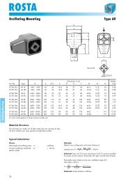
<strong>ROSTA</strong><br />
Rubber Suspension Unit<br />
Type DW-A<br />
D<br />
B<br />
S<br />
DW-A 60 to100<br />
L1<br />
L<br />
Q<br />
B<br />
A<br />
Ø I<br />
G<br />
H<br />
K<br />
N<br />
M<br />
P<br />
O<br />
Rubber Suspension Units<br />
DW-A 45 x 100 DW-A 50 x 200<br />
DW-A 50 x 120<br />
(Outer housing made out of spheroidal graphite cast iron)<br />
Weight<br />
Art. No. Type L L1 0<br />
– 0.3 A B D G H I K M N O P Q S T U in kg<br />
01 101 015 DW-A 45 x 100 100 110 Ø12 35 ± 0.5 78 115 145 – 22.5 65 – 8 – 41 45 13 20 2.9<br />
01 101 013 DW-A 50 x 120 120 130 M12 x 40 40 ± 0.5 87 130 170 17 x 27 35 60 – 12 – 45 50 17 27 3.7<br />
01 101 014 DW-A 50 x 200 200 210 M12 x 40 40 ± 0.5 87 130 170 17 x 27 35 70 – 12 – 45 50 17 27 6.1<br />
01 101 001 DW-A 60 x 150 150 160 M16 x 22 45 100 160 220 Ø18 50 60 60 8 130 65 60 – – 9.5<br />
01 101 002 DW-A 60 x 200 200 210 M16 x 22 45 100 160 220 Ø18 55 100 60 8 170 65 60 – – 11.8<br />
01 101 003 DW-A 60 x 300 300 310 M16 x 22 45 100 160 220 Ø18 55 200 60 8 270 65 60 – – 16.6<br />
01 101 004 DW-A 70 x 200 200 210 M20 x 28 50 120 200 260 Ø22 55 100 65 9 170 80 70 – – 16.6<br />
01 101 005 DW-A 70 x 300 300 310 M20 x 28 50 120 200 260 Ø22 55 200 65 9 270 80 70 – – 23.0<br />
01 101 006 DW-A 70 x 400 400 410 M20 x 28 50 120 200 260 Ø22 55 300 65 9 370 80 70 – – 29.5<br />
01 101 007 DW-A 80 x 200 200 210 M20 x 28 60 136 220 280 Ø22 65 80 80 10 170 85 80 – – 22.9<br />
01 101 008 DW-A 80 x 300 300 310 M20 x 28 60 136 220 280 Ø22 65 180 80 10 270 85 80 – – 31.7<br />
01 101 009 DW-A 80 x 400 400 410 M20 x 28 60 136 220 280 Ø22 65 280 80 10 370 85 80 – – 40.6<br />
01 101 010 DW-A 100 x 250 250 260 M24 x 32 75 170 300 380 Ø26 75 110 100 12 220 110 100 – – 45.7<br />
01 101 011 DW-A 100 x 400 400 410 M24 x 32 75 170 300 380 Ø26 75 260 100 12 370 110 100 – – 66.7<br />
01 101 012 DW-A 100 x 500 500 510 M24 x 32 75 170 300 380 Ø26 75 360 100 12 470 110 100 – – 80.7<br />
Torque M in Nm at<br />
Art. No. Type 5° 10° 15° 20° 25° 30°<br />
01 101 015 DW-A 45 x 100 34.5 78 130 200 278 400<br />
01 101 013 DW-A 50 x 120 51 133 250 395 570 780<br />
01 101 014 DW-A 50 x 200 102 260 475 745 1070 1450<br />
01 101 001 DW-A 60 x 150 75 170 300 460 700 1010<br />
01 101 002 DW-A 60 x 200 95 220 385 610 930 1380<br />
01 101 003 DW-A 60 x 300 140 365 630 995 1550 2240<br />
01 101 004 DW-A 70 x 200 140 380 650 1040 1490 2120<br />
01 101 005 DW-A 70 x 300 190 525 910 1470 2160 3150<br />
01 101 006 DW-A 70 x 400 250 765 1315 2160 3175 4750<br />
01 101 007 DW-A 80 x 200 200 500 850 1300 1900 2700<br />
01 101 008 DW-A 80 x 300 300 800 1300 2000 2900 4100<br />
01 101 009 DW-A 80 x 400 400 1060 1800 2800 3900 5600<br />
01 101 010 DW-A 100 x 250 400 1080 1800 2800 4100 6300<br />
01 101 011 DW-A 100 x 400 640 1700 2900 4500 6600 10000<br />
01 101 012 DW-A 100 x 500 800 2160 3600 5600 8200 12000<br />
26
<strong>ROSTA</strong><br />
Rubber Suspension Unit<br />
Accessories<br />
Clamp Type BR<br />
Weight<br />
Art. No. Type D G H I K M in kg<br />
01 500 001 BR 11 20 37 50 6 20 2.5 0.03<br />
01 500 002 BR 15 27 50 65 7 25 2.5 0.04<br />
01 500 003 BR 18 32 60 80 9 30 2.5 0.08<br />
01 500 004 BR 27 45 80 105 11 35 3.5 0.15<br />
01 500 005 BR 38 60 100 125 13 40 4.5 0.27<br />
01 500 006 BR 45 72 115 145 13 45 5.5 0.45<br />
01 500 007 BR 50 78 130 170 18 50 6.5 0.66<br />
Clamp Type BK<br />
Rubber Suspension Units<br />
Weight<br />
Art. No. Type D G H I K M N O in kg<br />
01 520 001 BK 11 28 45 60 6.5 20 1.5 6 15.5 0.04<br />
01 520 002 BK 15 36 55 75 6.5 25 2.0 7 20 0.09<br />
01 520 003 BK 18 45 68 90 8.5 30 2.0 8 24.5 0.14<br />
01 520 004 BK 27 62 92 125 10.5 35 2.5 10 33.5 0.29<br />
01 520 005 BK 38 80 115 150 12.5 40 3.0 11 43 0.45<br />
01 520 006 BK 45 95 130 165 12.5 45 3.5 13 51 0.68<br />
01 520 007 BK 50 108 152 195 16.5 50 4.0 15 58 0.93<br />
Bracket Type WS<br />
F<br />
fit for<br />
Weight<br />
Art. No. Type SE- DR-A, … A B C D E F G H J K L M N O in kg<br />
06 590 001 WS 11 – 15 11 15 6.5 5.5 7.5 7.5 30 13.5 11.5 27 4 45 30 46 35 10 0.08<br />
06 590 002 WS 15 – 18 15 18 8.5 6.5 7.5 7.5 40 13.5 13.5 34 5 55 32 58 44 12 0.15<br />
06 590 003 WS 18 – 27 18 27 10.5 8.5 9.5 10.5 50 15.5 16.5 43 6 70 38 74 55 20 0.28<br />
06 590 004 WS 27 – 38 27 38 12.5 10.5 11.5 12.5 65 21.5 21.5 57 8 90 52 98 75 25 0.70<br />
06 590 005 WS 38 – 45 38 45 16.5 12.5 14.5 15.5 80 24.5 21.5 66 8 110 55 116 85 35 0.90<br />
06 590 006 WS 45 – 50 45 50 20.5 12.5 18.5 20.5 100 30.5 26.5 80 10 140 66 140 110 40 1.80<br />
Bore A is designed for the fixation of the <strong>ROSTA</strong> tensioner devices type SE. Bores B are designed for the fixation of the <strong>ROSTA</strong> rubber suspension units type DR-A, DK-A, DO-A.<br />
27
<strong>ROSTA</strong><br />
Installations<br />
Rubber Suspension Units<br />
Lever bearing in concrete mixer Pressure rollers in saw device Pendulum on harrow rollers<br />
Conveyor-belt scraper Handle-bar insulation See-saw support<br />
Elastical brush and scraper suspension Suspended crane rail Shock absorber<br />
Control unit insulation Chain and belt tensioner Independent wheel suspension<br />
28
<strong>ROSTA</strong><br />
Installations<br />
Pendulum on amusement ride Compensation bearing for car brush Impact suspension in feeder<br />
Rubber Suspension Units<br />
Double suspension Motor base Shaker conveyor<br />
Compactor-suspension Guide rail Suspended pawl<br />
Impact-idler suspension Passive insulation Suspended unbalanced motor<br />
29
<strong>ROSTA</strong><br />
Fixation and Connecting Recommendations<br />
Fixations to Housing<br />
Rubber Suspension Units<br />
Fig. 1 Square tubular housing with clamp BR Fig. 2 Round housing with clamp BK<br />
Fig. 3<br />
Outer housing in clamping jaw<br />
Fig. 4<br />
Double bracket welded on housing<br />
Fig. 5 Plug-in connection (also see page 19) Fig. 6 Dual-thread welded on housing<br />
Fig. 7 Dual-levers welded on housing Fig. 8 Bridge-clamp over housing<br />
Fig. 9 Flange welded on housing Fig. 10 Housing in cast iron<br />
30
<strong>ROSTA</strong><br />
Fixation and Connecting Recommendations<br />
Fixations to Inner Square Section<br />
Fig. 11<br />
Inner square section with four through bores<br />
and bracket UV<br />
Fig. 12<br />
Inner square section with four through bores<br />
and brackets WS<br />
Rubber Suspension Units<br />
Fig. 13<br />
Plug-in connection with lever and welded-on<br />
square steel piece<br />
Fig. 14<br />
Lever connection with one through bolt<br />
Fig. 15<br />
Inner square section made of solid metal and machined<br />
threads on both sides<br />
Fig. 16<br />
Inner square section made of solid metal and cross bores<br />
on both protruding sides<br />
Fig. 17<br />
Inner square section with four through bores<br />
and bolted-on lever (see page 20)<br />
Fig. 18<br />
Inner square section made of solid steel<br />
and welded-on bracket<br />
Fig. 19 Inner square section with a central through bore (see page 21) Fig. 20 Inner square section made of solid steel and welded-on flange<br />
31
<strong>ROSTA</strong><br />
Applications<br />
Rubber Suspension Units<br />
Elastic stop to absorb high impacts Elastic suspension of a rake Suspension of a brush in road sweeper<br />
in potato harvester<br />
Elastic suspension of caliper roll in elevator<br />
“Floating” suspension of weighing device in belt conveyor<br />
Elastic suspension of shaping knive in baler<br />
Elastic caliper roll suspension in cardboard rolling machine<br />
32