AM/FM RADIO/CD PLAYER INTERCOM SYSTEM - NuTone
AM/FM RADIO/CD PLAYER INTERCOM SYSTEM - NuTone
AM/FM RADIO/CD PLAYER INTERCOM SYSTEM - NuTone

You also want an ePaper? Increase the reach of your titles
YUMPU automatically turns print PDFs into web optimized ePapers that Google loves.
<strong>AM</strong>/<strong>FM</strong><br />
<strong>RADIO</strong>/<strong>CD</strong> <strong>PLAYER</strong><br />
<strong>INTERCOM</strong> <strong>SYSTEM</strong><br />
MODEL: IMA-4406 SERIES MASTER STATION<br />
PUSHBUTTON<br />
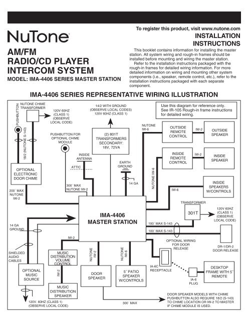
This booklet contains information for installing the master<br />
station. All system wiring and rough-in frames should be<br />
installed before mounting and wiring the master station.<br />
Refer to the installation instructions packaged with the<br />
rough-in frames for detailed wiring information. For more<br />
detailed information on wiring and mounting other system<br />
components (i.e., speaker, remote control, etc.), refer to the<br />
installation instructions packaged with each separate<br />
component.<br />
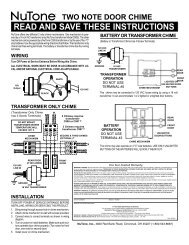
IMA-4406 SERIES REPRESENTATIVE WIRING ILLUSTRATION<br />
NUTONE CHIME<br />
TRANSFORMER<br />
18/2 (NUTONE S-143)<br />
OPTIONAL<br />
ELECTRONIC<br />
DOOR CHIME<br />
200´ MAX<br />
NUTONE<br />
IW-2<br />
14 GA<br />
GROUND<br />
SHIELDED<br />
AUDIO<br />
CABLES<br />
OPTIONAL<br />
MUSIC<br />
SOURCE<br />
120V 60HZ<br />
(CLASS 1)<br />
(OBSERVE<br />
LOCAL CODE)<br />
PUSHBUTTON FOR<br />
OPTIONAL CHIME<br />
MODULE<br />
IW-2<br />
120V. 60HZ (CLASS 1)<br />
(OBSERVE LOCAL CODE)<br />
INSIDE<br />
ANTENNA<br />
ATTIC<br />
300´ MAX<br />
NUTONE IW-2<br />
IW-2<br />
MUSIC<br />
DISTRIBUTION<br />
VOLUME<br />
CONTROL<br />
MUSIC<br />
DISTRIBUTION<br />
SPEAKER<br />
14/2 WITH GROUND<br />
(OBSERVE LOCAL CODES)<br />
120V 60HZ (CLASS 1)<br />
NUTONE<br />
IW-2<br />
(2) 801T<br />
TRANSFORMERS<br />
SECONDARY:<br />
18V, 72VA<br />
DOOR<br />
SPEAKER<br />
EARTH<br />
GROUND<br />
NUTONE<br />
IW-6<br />
14 GA<br />
IMA-4406<br />
MASTER STATION<br />
5˝ PATIO<br />
SPEAKER<br />
W/CONTROLS<br />
300´ MAX<br />
To register this product, visit www.nutone.com<br />
INSTALLATION<br />
NUTONE<br />
IW-6<br />
NUTONE IW-6<br />
100´ MAX S-143<br />
100´ MAX S-143<br />
IA-6C<br />
RECEPTACLE<br />
OUTSIDE<br />
REMOTE<br />
CONTROL<br />
INSIDE<br />
REMOTE<br />
CONTROL<br />
IW-6<br />
TRANSFORMER<br />
301T<br />
OPTIONAL WIRING<br />
FOR DOOR<br />
RELEASE<br />
INSTRUCTIONS<br />
Use this diagram for reference only.<br />
See IR-105 Rough-in frame instructions<br />
for detailed wiring.<br />
IA-6<br />
PLUG<br />
IW-2<br />
IW-2<br />
OUTSIDE<br />
SPEAKER<br />
INSIDE<br />
SPEAKER<br />
INSIDE<br />
SPEAKERS<br />
W/CONTROLS<br />
120V 60HZ<br />
(CLASS 1)<br />
(OBSERVE<br />
LOCAL CODE)<br />
DR-1/DR-2<br />
DOOR RELEASE<br />
DESKTOP<br />
FR<strong>AM</strong>E WITH 5˝<br />
REMOTE<br />
DOOR SPEAKER MODELS WITH CHIME<br />
PUSHBUTTON ALSO REQUIRE 18/2 (S-143)<br />
TO CHIME LOCATION OR IW-2 TO MASTER<br />
IF CHIME MODULE IS USED.
INSTALLATION<br />
TABLE OF CONTENTS<br />
INSTALLATION PAGE<br />
Contents of Carton . . . . . . . . . . . . . . . . . . . . . . . . . . . . . . . . . . . . . . . . . . . . . . . . . . . . . . . . . . . . . . . . . . . . . . . . . . . . .3<br />
Precautions and Guidelines . . . . . . . . . . . . . . . . . . . . . . . . . . . . . . . . . . . . . . . . . . . . . . . . . . . . . . . . . . . . . . . . . . . . . .3<br />
Wiring Specifications . . . . . . . . . . . . . . . . . . . . . . . . . . . . . . . . . . . . . . . . . . . . . . . . . . . . . . . . . . . . . . . . . . . . . . . . . . .3<br />
Remote Station Wiring . . . . . . . . . . . . . . . . . . . . . . . . . . . . . . . . . . . . . . . . . . . . . . . . . . . . . . . . . . . . . . . . . . . . . . . . . .3<br />
Maximum Number of Remote Stations . . . . . . . . . . . . . . . . . . . . . . . . . . . . . . . . . . . . . . . . . . . . . . . . . . . . . . . . . . . . . .3<br />
Mounting the Terminal Board . . . . . . . . . . . . . . . . . . . . . . . . . . . . . . . . . . . . . . . . . . . . . . . . . . . . . . . . . . . . . . . . . . . . .4<br />
Connecting the Remote Wiring . . . . . . . . . . . . . . . . . . . . . . . . . . . . . . . . . . . . . . . . . . . . . . . . . . . . . . . . . . . . . . . . . . . .4<br />
Connecting Volume Control Wiring . . . . . . . . . . . . . . . . . . . . . . . . . . . . . . . . . . . . . . . . . . . . . . . . . . . . . . . . . . . . . . . .5<br />
Connecting Door Speaker Wiring . . . . . . . . . . . . . . . . . . . . . . . . . . . . . . . . . . . . . . . . . . . . . . . . . . . . . . . . . . . . . . . . . .5<br />
Preparing Master Station Panel for Optional Door Release Pushbutton . . . . . . . . . . . . . . . . . . . . . . . . . . . . . . . . . . . .5<br />
Mounting the Optional Chime Module in the Master Station Panel . . . . . . . . . . . . . . . . . . . . . . . . . . . . . . . . . . . . . .5, 6<br />
Mounting the Master Station . . . . . . . . . . . . . . . . . . . . . . . . . . . . . . . . . . . . . . . . . . . . . . . . . . . . . . . . . . . . . . . . . . . . . .6<br />
Connecting the Power Transformers . . . . . . . . . . . . . . . . . . . . . . . . . . . . . . . . . . . . . . . . . . . . . . . . . . . . . . . . . . . . . . .7<br />
Mounting the Transformer Cover . . . . . . . . . . . . . . . . . . . . . . . . . . . . . . . . . . . . . . . . . . . . . . . . . . . . . . . . . . . . . . . . . .7<br />
Connecting the Master Station to the Terminal Board . . . . . . . . . . . . . . . . . . . . . . . . . . . . . . . . . . . . . . . . . . . . . . . . . .8<br />
Connecting the Radio Antenna . . . . . . . . . . . . . . . . . . . . . . . . . . . . . . . . . . . . . . . . . . . . . . . . . . . . . . . . . . . . . . . . . . . .9<br />
Connecting the Optional Chime Module . . . . . . . . . . . . . . . . . . . . . . . . . . . . . . . . . . . . . . . . . . . . . . . . . . . . . . . . . . . . .9<br />
Connecting Optional Electronic Chime . . . . . . . . . . . . . . . . . . . . . . . . . . . . . . . . . . . . . . . . . . . . . . . . . . . . . . . . . . . . . .9<br />
Connecting Optional Accessories . . . . . . . . . . . . . . . . . . . . . . . . . . . . . . . . . . . . . . . . . . . . . . . . . . . . . . . . . . . . . . . . .10<br />
Connecting Power to the Optional CP-95 Cassette Player . . . . . . . . . . . . . . . . . . . . . . . . . . . . . . . . . . . . . . . . . . . . .10<br />
Mounting and Connecting Optional Door Release Pushbutton . . . . . . . . . . . . . . . . . . . . . . . . . . . . . . . . . . . . . . . . . .11<br />
Connecting the Memory Back Up Battery . . . . . . . . . . . . . . . . . . . . . . . . . . . . . . . . . . . . . . . . . . . . . . . . . . . . . . . . . .11<br />
Securing the Master Panel . . . . . . . . . . . . . . . . . . . . . . . . . . . . . . . . . . . . . . . . . . . . . . . . . . . . . . . . . . . . . . . . . . . . . .11<br />
Powering Up the System . . . . . . . . . . . . . . . . . . . . . . . . . . . . . . . . . . . . . . . . . . . . . . . . . . . . . . . . . . . . . . . . . . . . . . .11<br />
OPERATIONAL CHECKOUT<br />
System Operating Controls . . . . . . . . . . . . . . . . . . . . . . . . . . . . . . . . . . . . . . . . . . . . . . . . . . . . . . . . . . . . . . . . . . . . .12<br />
Digital Clock . . . . . . . . . . . . . . . . . . . . . . . . . . . . . . . . . . . . . . . . . . . . . . . . . . . . . . . . . . . . . . . . . . . . . . . . . . . . . . . . .13<br />
System Checkout . . . . . . . . . . . . . . . . . . . . . . . . . . . . . . . . . . . . . . . . . . . . . . . . . . . . . . . . . . . . . . . . . . . . . . . . . . . . .13<br />
Setting Program Audio Controls . . . . . . . . . . . . . . . . . . . . . . . . . . . . . . . . . . . . . . . . . . . . . . . . . . . . . . . . . . . . . . .13, 14<br />
Setting Intercom Volume . . . . . . . . . . . . . . . . . . . . . . . . . . . . . . . . . . . . . . . . . . . . . . . . . . . . . . . . . . . . . . . . . . . . . . .14<br />
Setting Internal Intercom Volume Control . . . . . . . . . . . . . . . . . . . . . . . . . . . . . . . . . . . . . . . . . . . . . . . . . . . . . . . . . . .14<br />
Setting the BEEP Tone Level . . . . . . . . . . . . . . . . . . . . . . . . . . . . . . . . . . . . . . . . . . . . . . . . . . . . . . . . . . . . . . . . . . . .14<br />
Setting the External Audio Source Level . . . . . . . . . . . . . . . . . . . . . . . . . . . . . . . . . . . . . . . . . . . . . . . . . . . . . . . . . . .14<br />
Diagnostic Tests . . . . . . . . . . . . . . . . . . . . . . . . . . . . . . . . . . . . . . . . . . . . . . . . . . . . . . . . . . . . . . . . . . . . . . . . . . . . . .15<br />
Resetting the Microprocessor . . . . . . . . . . . . . . . . . . . . . . . . . . . . . . . . . . . . . . . . . . . . . . . . . . . . . . . . . . . . . . . . . . . .15<br />
INSTALLER’S TROUBLESHOOTNG GUIDE . . . . . . . . . . . . . . . . . . . . . . . . . . . . . . . . . . . . . . . . . . . . . .16, 17, 18<br />
WARRANTY . . . . . . . . . . . . . . . . . . . . . . . . . . . . . . . . . . . . . . . . . . . . . . . . . . . . . . . . . . . . . . . . . . . . . . . . . . . . . . . . . . .20<br />
2
INSTALLATION<br />
CONTENTS OF CARTON<br />
Check (✓) for the following IMA-4406 carton contents.<br />
❏ IMA-4406 master station<br />
❏ Terminal board<br />
❏ Transformer cover<br />
❏ Hardware bag assembly containing:<br />
2 - shoulder screws<br />
12 - No. 6 x 3/8 screws<br />
4 - colored panel mounting screws<br />
4 - ‘L’ panel mounting brackets<br />
❏ Homeowner’s manual with room labels<br />
❏ Installation instructions<br />
❏ Product Registration Warranty Card<br />
NOTE TO INSTALLER: Do not discard these<br />
installation instructions. Please transfer all<br />
installation instructions, warranty registration<br />
and homeowner’s manual to the homeowner.<br />
PRECAUTIONS AND GUIDELINES<br />
The <strong>NuTone</strong> IMA-4406 master station has been designed for<br />
ease of installation. Please read and follow ALL installation<br />
instructions, guidelines and precautions. Any deviation from<br />
these instructions or miswiring combinations may result in<br />
unit failure and void of warranty.<br />
WARNING!<br />
120 Volt AC Power to Transformers in the IR-105<br />
Rough-in MUST Remain OFF until ALL System Wiring<br />
at the Master and Remote Stations is Complete.<br />
• Observe all local building regulatory codes in your area.<br />
• All screw terminals at the master and remote stations must<br />
be secure.<br />
• Observe all color code connections of wires when<br />
connecting the remote stations to the master.<br />
• The IMA-4406 is designed to be installed with only <strong>NuTone</strong><br />
specified wire. No other wire should be used. The use of<br />
wire other than <strong>NuTone</strong> wire will void all <strong>NuTone</strong> warranties<br />
and may result in faulty installation and improper operation.<br />
IMPORTANT WARNING!<br />
THE POWER TRANSFORMER CONTAINS AN<br />
INTERNAL FUSE.<br />
DO NOT SHORT THE LOW VOLTAGE CONNECTING<br />
SCREWS OF THE TRANSFORMER OR THE<br />
TRANSFORMER WILL BE DESTROYED!<br />
WIRING SPECIFICATIONS<br />
See the IR-105 master rough-in frame installation instructions<br />
for detailed wiring information.<br />
Use <strong>NuTone</strong> IW-6, 3 twisted pair for connecting:<br />
• Remote controls to master<br />
• Remote stations to master<br />
3<br />
Use <strong>NuTone</strong> IW-2, 22 ga. twisted pair for connecting:<br />
• Door speakers to master<br />
• Remote controls to speakers<br />
• Speaker volume control (IC901) to master<br />
• Speaker volume control (IC901) to speakers<br />
• Electronic chime audio output to master<br />
• Pushbutton to chime module<br />
Use <strong>NuTone</strong> S-143, 18 ga. twisted pair for connecting:<br />
• Pushbutton to electronic chime<br />
• Electronic chime to chime transformer<br />
Use Nº14/2 power cable with ground, Class 1 UL Listed<br />
(Observe local codes) for connecting:<br />
• Transformers to 120v AC<br />
Use shielded audio cable for connecting external audio<br />
sources to the master station.<br />
REMOTE STATION WIRING<br />
An individual 6-wire cable (IW-6) must be connected from<br />
each remote station or remote control location to the master<br />
station’s terminal board.<br />
Maximum station wire length: 750 ft.<br />
IMPORTANT! <strong>NuTone</strong> cannot be responsible for<br />
improper system operation that results from<br />
interference generated by light dimmers, fluorescent<br />
lighting fixtures, and similar electrical products. Such<br />
interference must be corrected at the source. TO HELP<br />
REDUCE THIS INTERFERENCE, ALL WIRING<br />
CONNECTIONS TO THE MASTER MUST BE PLACED<br />
AT LEAST 12 INCHES FROM ANY AC POWER WIRING.<br />
AVOID RUNNING <strong>INTERCOM</strong> WIRES PARALLEL TO<br />
AC POWER WIRING.<br />
Maximum total length of IW-6 cable per system: 4,000 ft.<br />
MAXIMUM NUMBER OF REMOTE<br />
STATIONS<br />
The master station will accommodate up to 9 connections<br />
at the terminal board. These connections can be any<br />
combination of remote stations, remote controls or volume<br />
NOTE: NEVER connect more than one remote<br />
station to a set of screw terminals.<br />
controls. It will also accommodate 3 door speaker<br />
connections.<br />
If more than 9 stations are required, use the optional<br />
Model Nº IAA-440 expansion kit. This will allow an additional<br />
6 connections at the master.
INSTALLATION (Continued)<br />
WARNING! NEVER EXCEED A TOTAL OF 15 NUTONE<br />
25 OHM SPEAKERS ON THIS <strong>SYSTEM</strong>.<br />
WARNING! NEVER USE STANDARD 8 OHM STEREO<br />
SPEAKERS ON THIS <strong>SYSTEM</strong>. USE ONLY NUTONE<br />
SPECIFIED SPEAKERS ON THIS MASTER.<br />
MOUNTING THE TERMINAL BOARD<br />
1. Remove and clean any drywall debris or dust from the<br />
rough-in before beginning installation.<br />
2. Refer to Figure 1. Locate the terminal board in the left<br />
rear section of the rough-in frame.<br />
3. Use four (4) Nº 6 x 3 ⁄8“ screws supplied to secure the<br />
terminal board to the rough-in frame.<br />
4. Make certain the lower right-hand screw is secure and<br />
snug against the ground lug which covers the mounting<br />
hole in the terminal board. Do not bend ground lug.<br />
Make sure it is positioned between the screw and<br />
terminal board.<br />
IMPORTANT<br />
DO NOT APPLY POWER TO THE <strong>SYSTEM</strong> UNTIL ALL<br />
CONNECTIONS ARE COMPLETE AT THE MASTER<br />
AND REMOTE STATIONS.<br />
▲<br />
All Remote Stations, Remote Controls, Speaker<br />
Volume Controls, and Door Speaker Wiring MUST<br />
Return Directly to the Master Station. DO NOT<br />
CONNECT WIRING FROM SPEAKER TO SPEAKER!<br />
CONNECTING THE REMOTE WIRING<br />
1. Dress all remote wiring through the rectangular holes<br />
in the upper right and left sides of the rough-in frame.<br />
All wiring connections are made to the master station’s<br />
terminal board.<br />
▲<br />
FIGURE 1<br />
4<br />
2. Refer to Figure 2. Connect the IW-6 cable from each<br />
remote to the appropriate set of terminal screws at the<br />
master station’s terminal board. When connecting the<br />
cable to the terminal board, be sure to observe the<br />
matching of all color codes.<br />
Connect: RED to RED<br />
RED/WHT to RED/WHT<br />
BLK to BLK<br />
BLK/WHT to BLK/WHT<br />
ORN to ORN<br />
ORN/WHT to ORN/WHT<br />
Only connect one remote to each set of screw terminals.<br />
After completing all connections, check for any shorted<br />
wires. Dress cables flat against the terminal board to allow<br />
space for the master station to be properly secured.<br />
IW-6<br />
RED<br />
RED/WHT<br />
BLK<br />
BLK/WHT<br />
ORN<br />
ORN/WHT<br />
MOUNTING HOLES<br />
3. Refer to installation instructions packaged with the remote<br />
stations and remote controls for wiring these units.<br />
4. Refer to Figure 3. Use the Wire Matching Chart if you are<br />
retro-fitting a system with the previously used IW-6R cable.<br />
IMPORTANT – WHEN NUTONE MODEL IW-6R<br />
WIRING IS USED:<br />
CONNECT TO THE<br />
SCREW TERMINALS<br />
ON THE TERMINAL<br />
BOARD MARKED:<br />
BLUE STRIPE<br />
FIGURE 2<br />
1 ORN<br />
2 BLK<br />
3 BLK/WHITE<br />
4 ORN/WHITE<br />
5 RED<br />
6 RED/WHITE<br />
FIGURE 3<br />
CONNECTING VOLUME CONTROL WIRING
INSTALLATION (Continued)<br />
Refer to Figure 4. If a <strong>NuTone</strong> Volume Control is installed in<br />
the system, connect the control’s IW-2 wiring to the ORN and<br />
ORN/WHT screw terminals at the master station. Only ONE<br />
<strong>NuTone</strong> speaker may be connected to each volume<br />
control. Each volume control/speaker counts as a<br />
remote station. Remember: The maximum remote<br />
connections to the Master Station is 9. Adding the<br />
optional IAA-440 expansion module will increase the<br />
system remote capability to 15 stations.<br />
Refer to the installation instructions packed with the speaker<br />
ORN<br />
ORN/WHT<br />
NEVER USE 8 OHM STEREO SPEAKERS<br />
WITH THIS <strong>SYSTEM</strong>!<br />
volume control for wiring this unit.<br />
CONNECTING DOOR SPEAKER WIRING<br />
The Door Speakers connect to the Master Station Terminal<br />
Board with twisted pair IW-2 wire.<br />
1. Refer to Figure 5. Connect the two wires from the Door<br />
Speaker(s) to the 2 screw terminals marked DOOR<br />
SPEAKER on the master station terminal board.<br />
DOOR<br />
SPEAKER<br />
FIGURE 4<br />
FIGURE 5<br />
5<br />
PREPARING MASTER STATION PANEL FOR<br />
OPTIONAL DOOR RELEASE PUSHBUTTON<br />
To remove the pushbutton cover, position the master station<br />
face up. Be careful not to damage the cables on the back of<br />
the unit.<br />
1. Refer to Figure 6. Open the left-hand door on the master<br />
station panel.<br />
FIGURE 6<br />
2. Cut the 4 retainer webs from the pushbutton cover.<br />
3. Remove cover. The door release pushbutton will be<br />
installed and connected after the master panel has been<br />
mounted to the rough-in frame.<br />
MOUNTING THE OPTIONAL CHIME<br />
MODULE IN THE MASTER STATION PANEL<br />
1. Position the master station panel face down on a soft cloth.<br />
2. Refer to Figure 7. Align the optional <strong>NuTone</strong> IA-28 or<br />
IA-29 chime module onto the mounting bracket located in<br />
the master station.<br />
RED<br />
WIRE<br />
IA-29 ONLY<br />
SNAP IN PLACE<br />
FIGURE 7<br />
3. Apply firm, but even pressure to each side of the chime<br />
module until it snaps into place.<br />
4. Plug the 4 pin connector on the module into the connector<br />
located on the master. When properly installed, the ribbon<br />
cable will point away from the master station’s circuit<br />
boards, as illustrated.<br />
5. Connection from the pushbuttons to the master will be<br />
made after the master panel has been mounted.
INSTALLATION (Continued)<br />
Model IA-29 Only<br />
1. Refer to Figure 8. Locate the chime selector switch<br />
mounting bracket in the master unit.<br />
2. Remove and set aside the chime selector switch retaining<br />
screw located in the master unit.<br />
3. Remove and discard the square foam pads on the chime<br />
selector switch PC board connected to the chime module.<br />
4. Slide the PC board into the mounting bracket on the<br />
master station.<br />
5. Fasten the chime selector switch PC board with the<br />
retaining screw (earlier removed).<br />
MOUNTING THE MASTER STATION<br />
NOTE: If an optional IAA-440 expansion module is to be<br />
installed into the IMA-4406 master station, it should be<br />
installed before mounting the master station. Refer the<br />
installation instruction provided with the expansion module<br />
before performing the following mounting steps.<br />
1. Refer to Figure 9. Use two (2) #6x 3 ⁄8˝ screws per bracket<br />
to attach each of the four (4) mounting brackets to the<br />
rough-in frame. Before tightening, slide the bracket so it is<br />
flush with the wall surface (flush with rough-in frame if the<br />
rough-in is installed after the wall board). Tighten all eight<br />
(8) screws.<br />
6<br />
FIGURE 8<br />
FIGURE 9<br />
2. Refer to Figure 10A and 10B. For rough-in frames which<br />
are recessed into the wall opening, insert two (2) shoulder<br />
screws (provided) into the front two holes in the rough-in<br />
frame. For rough-in frames which are mounted flush with<br />
the wall, insert two (2) shoulder screws into the back two<br />
holes in the rough-in frame.<br />
BACK HOLE – FOR<br />
FLUSH MOUNTED<br />
ROUGH-INS<br />
FRONT HOLE –<br />
FOR RECESSED<br />
ROUGH-IN<br />
FIGURE 10A FIGURE 10B<br />
3. Refer to Figure 11. Attach master panel to rough-in<br />
frame by placing mounting hinge keyhole slots over<br />
shoulder screw heads in the rough-in frame.<br />
4. Refer to Figure 12. Slide master station panel to the right,<br />
then forward until it is flush with the wall surface.<br />
5. Align master panel with rough-in frame.<br />
FIGURE 11 FIGURE 12<br />
6. Refer to Figure 13. Attach support strap to rough-in<br />
frame by attaching metal hook into hole in top of rough-in<br />
frame. Using pliers, squeeze hook closed. Hook must not<br />
come loose when master is later secured.<br />
FIGURE 13
INSTALLATION (Continued)<br />
CONNECTING THE<br />
POWER TRANSFORMERS<br />
CAUTION<br />
BE SURE THE AC POWER IS OFF BEFORE<br />
CONNECTING THE POWER TRANSFORMERS. DO<br />
NOT TURN AC POWER ON TO TRANSFORMERS<br />
UNTIL ALL WIRING AT THE REMOTE AND MASTER<br />
STATIONS IS COMPLETE!<br />
▲<br />
1. Refer to Figure 14. The transformers’ primary leads<br />
should already be connected to the 120 volt AC house<br />
supply wiring. Be sure power is off before connecting<br />
IMPORTANT WARNING!<br />
THE POWER TRANSFORMER CONTAINS AN<br />
INTERNAL FUSE.<br />
DO NOT SHORT THE LOW VOLTAGE CONNECTING<br />
SCREWS OF THE TRANSFORMER OR THE<br />
TRANSFORMER WILL BE DESTROYED!<br />
transformers to master unit.<br />
2. Locate the two (2) sets of red/wht transformer leads on<br />
the lower left corner of the master unit. Connect one pair<br />
of low voltage leads to each transformer located in the<br />
bottom of the rough-in.<br />
▲<br />
7<br />
MOUNTING THE TRANSFORMER COVER<br />
IMPORTANT: The transformer cover must be installed<br />
for proper operation of the intercom.<br />
1. Refer to Figure 15. Remove the left front and right rear<br />
screws from the transformer enclosure. Set screws aside<br />
for later installation.<br />
2. Position the transformer cover (with insulator positioned<br />
towards transformers) over the transformer enclosure so<br />
holes in cover align with holes in enclosure.<br />
3. Fasten cover with two (2) screws previously removed.<br />
FIGURE 14<br />
FIGURE 15
INSTALLATION (Continued)<br />
CONNECTING THE MASTER STATION TO<br />
THE TERMINAL BOARD<br />
1. Refer to Figures 16 and 17. Plug all five connectors into<br />
the terminal board.<br />
1. • Insert black ribbon cable with 10 pin plug into CN104<br />
connector.<br />
1. • Insert multi-color ribbon cable with 14 pin plug into<br />
CN102 connector.<br />
1. • Insert multi-color ribbon cable with 9 pin plug into CN106<br />
connector.<br />
1. • Insert brown shielded cable with 12 pin plug into CN101<br />
connector.<br />
1. • Insert gray shielded cable with 11 pin plug into CN116<br />
connector.<br />
1. • No connection is made to connector CN111 unless<br />
IAA-440 expansion module is used.<br />
2. Make sure the alignment keys are properly aligned before<br />
applying pressure to the connector.<br />
3. After all connectors are plugged into the terminal board,<br />
position the extra ribbon cable length toward the top of the<br />
rough-in frame.<br />
4. If an IAA-440 expansion module is included in this<br />
installation, proceed with the connection of the module to<br />
the expansion module terminal board at this time. Refer to<br />
the installation instructions provided with the expansion<br />
module.<br />
MULTI-COLOR<br />
RIBBON CABLE<br />
WITH 9 PIN PLUG<br />
BROWN CABLE<br />
WITH 12 PIN<br />
PLUG<br />
BLACK RIBBON<br />
CABLE WITH<br />
10 PIN PLUG<br />
MULTI-COLOR<br />
RIBBON CABLE<br />
WITH 14 PIN<br />
PLUG<br />
CN104<br />
8<br />
CN106<br />
CN101<br />
CN102<br />
CN116<br />
GRAY CABLE<br />
WITH 11 PIN<br />
PLUG<br />
FIGURE 16<br />
CN111<br />
USED WITH<br />
OPTIONAL IAA-440<br />
EXPANSION<br />
MODULE<br />
FIGURE 17
INSTALLATION (Continued)<br />
CONNECTING THE <strong>RADIO</strong> ANTENNA<br />
1. Refer to Figure 18. Plug radio antenna (supplied with<br />
IR105 rough-in frame) into the 2-pin connector located on<br />
the main circuit board. Be certain the tab on the connector<br />
is facing towards the top of the master unit, as illustrated.<br />
NOTE: Any excess antenna cable should be located<br />
outside of Rough-in.<br />
In most locations the antenna supplied with the rough-in<br />
frame provides adequate <strong>AM</strong> reception; however, in rural or<br />
weak signal areas, a separate <strong>AM</strong> antenna may be required.<br />
Refer to the following instruction when selecting and<br />
connecting an <strong>AM</strong> antenna.<br />
1. Refer to Figure 19. Move the auxiliary antenna selector<br />
switch to the <strong>AM</strong> position.<br />
2. Connect 50 feet of 22 ga. insulated wire to the screw<br />
terminal marked <strong>AM</strong> ANTENNA.<br />
3. Run the wire from the master station location to the attic.<br />
Fasten the insulated wire at one end of the attic; stretch<br />
the wire to its full length and fasten at the opposite end.<br />
Fasten the insulated wire at several locations between<br />
ends to prevent sagging.<br />
<strong>AM</strong> ONLY<br />
<strong>AM</strong> ANTENNA<br />
<strong>AM</strong>/<strong>FM</strong><br />
TAB<br />
FIGURE 18<br />
FIGURE 19<br />
9<br />
CONNECTING THE OPTIONAL<br />
CHIME MODULE<br />
It is now time to connect the optional chime module that you<br />
earlier installed into the master station.<br />
1. Refer to Figure 20. Identify the front chime pushbutton<br />
wires.<br />
2. Connect the front pushbutton wires to the screw terminals<br />
marked FRONT and COMMON on the chime module.<br />
3. Repeat steps 1 and 2 for the REAR and SIDE chime<br />
pushbuttons.<br />
4. Refer to the instructions packed with the chime module<br />
for information on chime volume level and chime tune<br />
selection (IA-29 only).<br />
CHIME<br />
VOLUME<br />
FRONT<br />
CONNECTING OPTIONAL<br />
ELECTRONIC CHIME<br />
1. Refer to Figure 21. Connect <strong>NuTone</strong> IW-2 cable from the<br />
chime to the (+) and (-) screw terminals on the master<br />
station’s main circuit board.<br />
2. Refer to the instructions packed with the chime for<br />
complete wiring information.<br />
IMPORTANT: Failure to use <strong>NuTone</strong> IW-2 cable will<br />
cause the system to hum at all times.<br />
(–) (+)<br />
ELECTRONIC<br />
CHIME<br />
REAR<br />
SIDE<br />
COMMON<br />
FIGURE 20<br />
FIGURE 21
INSTALLATION (Continued)<br />
CONNECTING OPTIONAL ACCESSORIES<br />
1. Refer to Figure 22. To connect an external audio source<br />
(<strong>NuTone</strong> Model CP-95 cassette, stereo system, VCR, TV,<br />
etc. with low level audio output) to the IMA-4406 master<br />
station, locate the TAPE and AUXiliary inputs on the<br />
upper center of the master station’s main circuit board.<br />
2. Connect an RCA phono type plug to the shielded audio<br />
cable coming from the external audio source. Follow the<br />
phono plug manufacturer’s instructions when connecting<br />
to the cable.<br />
3. Insert the phono plug into the appropriate input jack<br />
(TAPE or AUX) on the master station’s main circuit board.<br />
NOTE: The TAPE and AUX inputs have input audio level<br />
controls to allow matching of the external audio source<br />
with the radio and <strong>CD</strong> audio of the master.<br />
4. To use the selected source audio for recording onto a<br />
cassette recorder, insert the recorder’s plug into the<br />
master station’s LINE OUT jack.<br />
5. Optional connection to provide program audio only:<br />
• The <strong>CD</strong>, radio or optional audio sources can be<br />
channeled through an auxiliary amplifier (purchase<br />
a <strong>NuTone</strong> Model IMA-516 separately) to provide<br />
uninterrupted music (no intercom) to separate<br />
speakers. This type of installation can be used for<br />
example, in a doctor’s office where intercom and<br />
music are desired in the office area, but music only<br />
is desired in the waiting room.<br />
• NOTE: If an auxiliary amplifier is used, connect the<br />
master station’s LINE OUT jacks to the auxiliary<br />
amplifier’s low-level audio input wires using shielded<br />
audio cable (not supplied by <strong>NuTone</strong>).<br />
• NOTE: When using the LINE OUT for recording<br />
program audio or distributing program audio only<br />
through an external amplifier, the automatic <strong>CD</strong> PAUSE<br />
should be disabled or the audio present on the LINE<br />
OUT jack will stop when the intercom or chime is used.<br />
To disable the <strong>CD</strong> PAUSE, refer to the homeowner’s<br />
manual.<br />
LINE OUT<br />
AUX INPUT<br />
10<br />
CONNECTING POWER TO THE OPTIONAL<br />
CP-95 CASSETTE <strong>PLAYER</strong><br />
1. Refer to Figure 23. Cut the protective sleeving from the end<br />
of the BLK/WHT CP-95 power supply leads.<br />
2. Separate 2 inches of the supply leads.<br />
3. Strip the outer insulation back approximately 5/8˝ from the<br />
end of the cable.<br />
4. Connect the power leads from the CP-95 to the CP-95 power<br />
supply leads of the master station (polarity is not important).<br />
Use wire nuts to protect the bare wires from shorting.<br />
FIGURE 23<br />
IMPORTANT<br />
Be sure the power to the transformers in the IR-105 rough-in<br />
is OFF before connecting the CP-95 power supply leads!!<br />
TAPE INPUT<br />
▲<br />
▲<br />
CONNECT CP-95<br />
POWER LEADS<br />
FIGURE 22
INSTALLATION (Continued)<br />
MOUNTING AND CONNECTING<br />
OPTIONAL DOOR RELEASE PUSHBUTTON<br />
You have previously prepared the master station for the<br />
optional release pushbutton.<br />
1. Refer to Figure 24. Feed one wire from the door release<br />
transformer and one wire from the door release mechanism<br />
through the pushbutton hole in the master station panel.<br />
2. Connect the two (2) wires to the PB1WHCL pushbutton.<br />
3. Rotate the pushbutton so the screws are on the top and<br />
bottom as illustrated, then snap the button into the<br />
mounting hole.<br />
CONNECTING THE MEMORY<br />
BACK UP BATTERY<br />
Refer to Figure 25. Connect the 2-pin plug from the battery<br />
to the connector located on the control circuit board.<br />
SECURING THE MASTER PANEL<br />
2 PIN PLUG<br />
1. Refer to Figure 26. Inspect all wiring connections to make<br />
sure they are complete and correct.<br />
2 PIN<br />
2. Make sure all antenna connections are secure. CONNECTOR<br />
3. Dress all remote station wires flat against the terminal<br />
board.<br />
4. Position the master station panel over the rough-in frame<br />
and align screw holes in master with mounting brackets.<br />
Two (2) mounting holes are located behind the <strong>CD</strong><br />
Player door.<br />
5. Secure the master station panel to the rough-in mounting<br />
brackets with four (4) screws (provided).<br />
NOTE: The mounting screws will pierce the wall surface FIGURE 25<br />
behind the mounting brackets. If the wall surface is hard, a<br />
PLEASE NOTE<br />
FIGURE 24<br />
If permanent AC power has not been connected, or the<br />
AC power will be off for long periods of time, the<br />
battery should not be connected at this time. When the<br />
battery is connected, the correct time and programmed<br />
radio memory stations will be retained for<br />
approximately 30 hours on battery backup.<br />
11<br />
clearance hole must be drilled behind the mounting bracket<br />
before securing the master station panel.<br />
POWERING UP THE <strong>SYSTEM</strong><br />
Once all connections have been completed throughout the<br />
system, it is time to apply power to the master station.<br />
CAUTION<br />
WHEN RAISING THE MASTER PANEL TO ITS FINAL<br />
POSITION, DO IT SLOWLY! BE CAREFUL NOT TO HIT OR<br />
D<strong>AM</strong>AGE ANY OF THE CIRCUIT BOARDS OR CABLES.<br />
FIGURE 26<br />
▲<br />
1. Apply power to the master station by turning on the circuit<br />
breaker that supplies power to the transformers in the<br />
IR-105 rough-in frame.<br />
2. When power is first applied, the L<strong>CD</strong> display will flash<br />
1:00 PM. Refer to the Operational Checkout section of<br />
this manual for additional information.<br />
▲
OPERATIONAL CHECKOUT<br />
<strong>SYSTEM</strong> OPERATING CONTROLS<br />
1<br />
2<br />
3<br />
4<br />
5<br />
6<br />
7<br />
8<br />
9<br />
10<br />
11<br />
12<br />
13<br />
14<br />
15<br />
16<br />
17<br />
18<br />
19<br />
20<br />
SCAN: Activates scan tuning during <strong>AM</strong>/<strong>FM</strong> operation.<br />
▲▼ UP/DOWN TUNING: Provides manual tuning of the <strong>AM</strong>/<strong>FM</strong> radio.<br />
MEMORY 1-6 KEYS: Provides direct access to stored radio<br />
frequencies.<br />
TRACK : Returns to the beginning of the current track and/or previous<br />
tracks.<br />
▲<br />
TRACK : Advances the <strong>CD</strong> Player to the beginning of the next track.<br />
▲<br />
RDM/RPT: (Random/Repeat) Set the <strong>CD</strong> play mode to: REPEAT ONE,<br />
REPEAT ALL or RANDOM PLAY.<br />
PLAY/PAUSE: Activates the operation of the <strong>CD</strong> Player. Pressing the<br />
key during play operation will pause the <strong>CD</strong> Player.<br />
SEARCH : Quickly searches the track in the forward direction.<br />
SEARCH : Quickly searches the track in the reverse direction.<br />
<strong>CD</strong> <strong>PLAYER</strong> DOOR: Open <strong>CD</strong> door and snap <strong>CD</strong> disc onto spindle.<br />
TIME SET: Used with the ▲ ▼ keys to set the clock and timer.<br />
MEMORY SET: Stores desired radio frequencies into a selected<br />
memory location.<br />
CLOSE: Press here to close <strong>CD</strong> Player door.<br />
TREBLE: Adjusts the high frequency audio content of the source audio.<br />
STOP: Ends the <strong>CD</strong> Play mode and turns off the program audio.<br />
BASS: Adjusts the low frequency audio content of the source audio.<br />
<strong>SYSTEM</strong> VOLUME: Adjusts the program audio level throughout the<br />
system.<br />
OPEN: Causes the <strong>CD</strong> Player door to open.<br />
LOUDNESS: Compensates for the bass and treble response the human<br />
ear has when listening to audio at low volume levels.<br />
MICROPROCESSOR RESET: Initiates a reset of the microprocessor.<br />
NOTE: A reset of the microprocessor will erase the system’s memory.<br />
33<br />
32<br />
31<br />
30<br />
29<br />
28<br />
27<br />
26<br />
25<br />
▲<br />
▲<br />
24<br />
12<br />
21<br />
22<br />
23<br />
24<br />
25<br />
26<br />
27<br />
28<br />
29<br />
30<br />
31<br />
32<br />
33<br />
1 2 3 4 5 6 7 8 9<br />
23<br />
22<br />
DISPLAY: Sets the L<strong>CD</strong> display mode: CLOCK, <strong>RADIO</strong> FREQUENCY,<br />
TRACK NUMBER or TIME PLAYED.<br />
<strong>INTERCOM</strong> VOLUME: Adjusts intercom audio level throughout the<br />
system.<br />
MASTER STATION STATUS SWITCHES: Sets the master station in<br />
one of the following modes: <strong>RADIO</strong>/<strong>INTERCOM</strong>, <strong>INTERCOM</strong> ONLY,<br />
OFF or MONITOR.<br />
REMOTE STATION STATUS SWITCHES: Sets the remote stations in<br />
one of the following modes: <strong>RADIO</strong>/<strong>INTERCOM</strong>, <strong>INTERCOM</strong> ONLY,<br />
OFF or MONITOR. Note: If the optional expansion module is installed, 6<br />
additional switches will be located on the right side of the master.<br />
DOOR RELEASE KNOCKOUT: Mounting hole for optional door<br />
release pushbutton.<br />
END CALL: Ends intercom communication and returns system to audio<br />
source.<br />
DOOR TALK: Initiates intercom communication to the door speakers.<br />
INSIDE/PATIO: Initiates intercom communication to remote stations.<br />
TIMER: Enables or disables the radio timer. The indicator light will<br />
illuminate next to the Timer key when the Radio Timer is activated.<br />
PROGR<strong>AM</strong> AUDIO SOURCE: Selects the program audio source: <strong>AM</strong>,<br />
<strong>FM</strong>, TAPE and AUX. The indicator light will illuminate next to the<br />
selected program audio source.<br />
ELECTRONIC CHIME TUNE SELECTION: Selects the tune of the<br />
optional <strong>NuTone</strong> IA-29 Chime Module.<br />
PROGR<strong>AM</strong> OFF: Turns off the selected program audio source. The<br />
program Off key does not affect the intercom or chime operation.<br />
MASTER VOLUME: Adjusts the volume at the master station.<br />
21 20 19 18 17 16 15 14 13 12 11 10
OPERATIONAL CHECKOUT (Continued)<br />
DIGITAL CLOCK<br />
SETTING THE TIME<br />
The proper clock setting procedure is arranged in 4<br />
segments. Each segment must be completed in 5 seconds.<br />
Follow the procedure below.<br />
1. Press the TIME SET key one time.<br />
The ‘Hours’ display will begin<br />
flashing, and the words ‘Set Time’<br />
will display.<br />
2. Within 5 seconds, press the ▲ or ▼ key until the correct<br />
Hour and <strong>AM</strong>/PM are displayed.<br />
3. Within the next 5 seconds, press the TIME SET key<br />
again. The ‘Minutes’ display will begin flashing.<br />
4. Again, within 5 seconds, press the ▲ and ▼ keys until the<br />
correct minute is displayed.<br />
5. Release the keys after entering the correct time. The<br />
display will stop flashing in 5 seconds, and the time will<br />
be set.<br />
NOTE: Pressing the ▲ or ▼ keys momentarily will cause the<br />
time to advance or reverse one digit. Pressing the ▲ or ▼<br />
keys continuously for more than 1⁄2 second will cause the<br />
digits to advance or reverse at high speed.<br />
<strong>SYSTEM</strong> CHECKOUT<br />
Set the following control settings and perform the indicated<br />
tests.<br />
1. Set all STATION STATUS SWITCHES to the <strong>RADIO</strong><br />
<strong>INTERCOM</strong> position.<br />
2. Set the MASTER VOLUME control to 2 ⁄3 position.<br />
3. Set each remote station VOLUME control to 2 ⁄3 position.<br />
4. Set the <strong>SYSTEM</strong> VOLUME control to 1 ⁄3 position.<br />
5. Set the <strong>INTERCOM</strong> VOLUME control to 2 ⁄3 position.<br />
6. Set the BASS and TREBLE control to 1 ⁄2 position.<br />
7. Press the OPEN key on the master station. The <strong>CD</strong><br />
Player door will open. Complete opening the door by<br />
moving the <strong>CD</strong> door from left to right.<br />
8. Snap a <strong>CD</strong> disc onto the spindle of the <strong>CD</strong> player.<br />
▲<br />
CAUTION<br />
SET TIME<br />
PM 1:00<br />
Never touch the lens of the <strong>CD</strong> player or damage<br />
will result!<br />
9. Close the <strong>CD</strong> player door by moving the door from right to<br />
left until the door latches closed.<br />
10. Tune in a strong local <strong>FM</strong> radio station as follows:<br />
• Press the <strong>FM</strong> key.<br />
• Locate a strong <strong>FM</strong> radio signal by using the ▲ ▼keys.<br />
Beginning with the master station, check each station in the<br />
system for proper operation using the following procedure.<br />
1. Press the INSIDE/PATIO key to initiate a call. Radio<br />
audio will mute.<br />
2. Release the INSIDE/PATIO key to hear the reply.<br />
▲<br />
13<br />
3. Press the END CALL key. Intercom communication will<br />
end and radio audio will return to all stations in the system.<br />
4. Press the DOOR TALK key. Radio audio will mute and<br />
audio from the initiating station will be heard at the door<br />
speaker(s) and all stations in the system.<br />
5. Release the DOOR TALK key. Audio from the door<br />
speaker(s) will be heard at all stations in the system.<br />
6. Press the END CALL key. Door communications will<br />
end and radio audio will return to all stations in the<br />
system.<br />
7. Press and hold the END CALL key for 2 seconds at any<br />
remote station. The radio will turn off.<br />
8. Press and hold the END CALL key for 2 seconds at any<br />
remote station. The radio will turn on. For additional<br />
information on remote radio control, refer to the<br />
homeowner’s manual.<br />
9. With a <strong>CD</strong> in the <strong>CD</strong> player, press and hold the END<br />
CALL key at any remote station until a BEEP BEEP is<br />
heard at the remote station. In a few moments, the <strong>CD</strong><br />
will begin playing.<br />
10. Press and hold the END CALL key for 2 seconds at any<br />
remote station. The <strong>CD</strong> player and audio will stop. For<br />
additional information on remote <strong>CD</strong> Player control, refer<br />
to the homeowner’s manual.<br />
11. Repeat procedure at all remote stations.<br />
SETTING PROGR<strong>AM</strong> AUDIO CONTROLS<br />
The volume levels required at each station may vary with the<br />
location of the speaker and the size of the room where the<br />
speaker is located. Spend some time experimenting with the<br />
volume levels, and adjust each speaker so that you can<br />
clearly hear the radio, <strong>CD</strong> and intercom. Use the following<br />
procedures to set your system’s volume levels.<br />
1. At each remote station, turn the VOLUME control<br />
completely clockwise to maximum volume.<br />
2. At the master station, set the REMOTE and MASTER<br />
SPEAKER STATUS SWITCHES to the <strong>RADIO</strong><br />
<strong>INTERCOM</strong> position.<br />
3. Turn the MASTER VOLUME control to maximum volume.<br />
4. Turn the <strong>SYSTEM</strong> VOLUME control on the master station<br />
to approximately 1 ⁄3 volume.<br />
5. Select an <strong>AM</strong> or <strong>FM</strong> radio station with a strong, clear signal.<br />
6. Adjust the master station’s <strong>SYSTEM</strong> VOLUME control<br />
until you have ample volume at the remote station that<br />
requires the highest volume (i.e. a large living room, family<br />
room, basement, etc.)<br />
PLEASE NOTE: The master station and all remote stations<br />
(except door speakers) are equipped with volume controls.<br />
Although the master station <strong>SYSTEM</strong> VOLUME sets the<br />
system’s volume level, you may adjust an individual<br />
speaker’s volume level as desired.
OPERATIONAL CHECKOUT (Continued)<br />
SETTING PROGR<strong>AM</strong> AUDIO CONTROLS<br />
(CONTINUED)<br />
7. Adjust the MASTER VOLUME control and all remote<br />
station’s volume controls to the volume level you desire.<br />
In order to have proper intercom audio levels, it is<br />
recommended that the MASTER VOLUME and remote<br />
stations’ VOLUME controls be set at 2 ⁄3 volume or higher.<br />
SETTING <strong>INTERCOM</strong> VOLUME<br />
1. Initiate an intercom call from the master by pressing the<br />
INSIDE/PATIO key.<br />
2. Speak with a clear normal voice about 2-3 feet from the<br />
master station’s speaker.<br />
3. Adjust the <strong>INTERCOM</strong> VOLUME control until the initiating<br />
station’s audio is clearly heard at all stations in the<br />
system.<br />
PLEASE NOTE: The volume control at all stations should be<br />
set between 1 ⁄2 to maximum volume for proper intercom<br />
operation.<br />
4. Repeat the above procedure at several remote station<br />
locations until an acceptable intercom audio level is<br />
achieved at all stations.<br />
SETTING INTERNAL <strong>INTERCOM</strong> VOLUME<br />
CONTROL<br />
The internal intercom volume control has been factory set for<br />
optimum intercom operation. Should the intercom gain need<br />
to be adjusted beyond the range of the Intercom Volume<br />
Control behind the left front door, use the following procedure:<br />
1. Refer to Figure 27. Using a thin-blade screwdriver, adjust<br />
the internal control counter-clockwise as viewed from the<br />
rear of the master station panel. This adjustment will<br />
reduce the intercom gain.<br />
2. To increase the intercom gain, turn the internal control<br />
clockwise.<br />
ROUGH-IN<br />
BOTTOM OF<br />
MASTER<br />
FIGURE 27<br />
14<br />
SETTING THE BEEP TONE LEVEL<br />
The internal BEEP tone volume control has been factory set<br />
to a normal level for the BEEP tone to be heard when the <strong>CD</strong><br />
Player operation is initiated from a remote station by using<br />
the <strong>AM</strong>/<strong>FM</strong>/<strong>CD</strong> CONTROL/END CALL key. Should that level<br />
require adjustment, use the following procedure:<br />
1. Refer to Figure 28. Using a thin-blade screwdriver, adjust<br />
the BEEP TONE volume control counter-clockwise as<br />
viewed from the rear of the master station panel to reduce<br />
the BEEP level.<br />
2. To increase the BEEP level, turn the control clockwise.<br />
BEEP TONE<br />
SETTING THE EXTERNAL AUDIO<br />
SOURCE LEVEL<br />
FIGURE 28<br />
The TAPE and AUX level controls have been factory set at<br />
maximum. These controls can be adjusted to match the<br />
external audio source level with the built-in radio and <strong>CD</strong><br />
Player levels. Use the following procedure:<br />
1. Press the <strong>FM</strong> key.<br />
2. Tune the radio to a strong local radio station.<br />
3. Turn on the external audio source(s) connected to the<br />
master station.<br />
4. Switch the master station from <strong>FM</strong> to TAPE or AUX.<br />
5. Refer to Figure 29. Using a thin-blade screwdriver, adjust<br />
the TAPE/AUX control to match the audio level of the<br />
external audio source with the <strong>FM</strong> radio.<br />
AUX TAPE<br />
LEVEL LEVEL<br />
FIGURE 29
OPERATIONAL CHECKOUT (Continued)<br />
DIAGNOSTIC TESTS<br />
The following diagnostic tests have been incorporated into<br />
the <strong>NuTone</strong> IMA-4406 master station to assist in system<br />
troubleshooting.<br />
• Master station keyboard test<br />
• Remote station control voltage test<br />
• Display test<br />
The following applies to all diagnostic tests:<br />
1. To access any of the diagnostic tests, the system must be<br />
in the PROGR<strong>AM</strong> OFF mode.<br />
2. Pressing the MEMORY SET key will end the current<br />
diagnostic test.<br />
3. The current diagnostic test will end after one minute of<br />
inactivity.<br />
PLEASE NOTE: An incorrect voltage caused<br />
by miswiring, shorted wiring or a defective<br />
remote station may cause the radio and/or <strong>CD</strong><br />
Player to turn off/on, thus preventing the unit<br />
from entering the diagnostic mode. Should this<br />
occur, the master station’s control timer will stop<br />
the on/off cycling after 30 seconds.<br />
Remote Station Keyboard Test – Verifies that all keys on<br />
the master station are functioning properly. To activate: Press<br />
and hold the following key in this order:<br />
1. ▲ key 3. Memory 1 key<br />
2. ▼ key 4. Release all keys<br />
In this mode, the hours in the display represents the current<br />
diagnostic test and the minutes indicate the current key being<br />
pressed. The following will be displayed as the key is<br />
pressed.<br />
KEY DISPLAY KEY DISPLAY<br />
No key 1:00 Memory 2 1:14<br />
Scan 1:01 Memory 3 1:15<br />
▲ 1:02 Memory 4 1:16<br />
▼ 1:03 Memory 5 1:17<br />
Program Off 1:04 Memory 6 1:18<br />
<strong>AM</strong> 1:05 Play/Pause 1:19<br />
<strong>FM</strong> 1:06 RDM/RPT 1:20<br />
Tape 1:07 Track 1:21<br />
Aux 1:08 Track 1:22<br />
Timer 1:09 Display 1:23<br />
Inside/Patio 1:10 Stop 1:24<br />
Door Talk 1:11 Time Set 1:25<br />
End Call 1:12 Memory Set 1:26<br />
Memory 1 1:13<br />
▲<br />
▲<br />
15<br />
Remote Station Control Voltage Test – Displays the<br />
voltage at the master’s microprocessor control line. To<br />
activate, press and hold the following keys:<br />
1. ▲ key 3. Memory 2 key<br />
2. ▼ key 4. Release all keys<br />
Example:<br />
Display Voltage at Microprocessor<br />
2:3.0 3.0 volts<br />
2:1.9 1.9 volts<br />
2:0.1 .1 volts<br />
In this mode, the hours represent the diagnostic test, and the<br />
minutes indicate the voltage at the master station’s<br />
microprocessor.<br />
Voltage Window<br />
Mode Maximum Minimum<br />
End Call .4 volts 0 volts<br />
Inside/Patio 2.4 volts 1.6 volts<br />
Door Talk 3.6 volts 2.8 volts<br />
Quiescent 5.0 volts 4.3 volts<br />
The control voltage windows for the three intercom modes<br />
and quiescent mode are listed above. For proper intercom<br />
operation, the control voltage produced when an intercom<br />
key is pressed at a remote station should fall between the<br />
voltage indicated.<br />
NOTE: Pressing the END CALL, DOOR TALK, or<br />
INSIDE/PATIO keys at the master station will not change the<br />
voltage on the control line. If a remote station does not<br />
produce a voltage within the above window for a specific<br />
intercom function, check the following:<br />
• Make sure all connections from the master station are<br />
properly installed at the terminal board.<br />
• Check IW-6 connections at the master station terminal<br />
board and at each remote station.<br />
• Confirm that the suspect remote station functions properly<br />
by replacing it with a known good remote station.<br />
Display Test – Displays all segments in the L<strong>CD</strong> display. To<br />
activate, press and hold the following in this order:<br />
1. ▲ key 3. Memory 3 key<br />
2. ▼ key 4. Release all keys<br />
RESETTING THE MICROPROCESSOR<br />
NOTE: Resetting the microprocessor will cause the radio<br />
memory channels and clock time to be lost.<br />
Should the system not operate properly, the internal<br />
microprocessor may require resetting. To reset the<br />
microprocessor, use the point of a pen to press the reset<br />
button through the access hole behind the right lower door.<br />
See “System Operating Control” section.
INSTALLER’S TROUBLESHOOTING GUIDE<br />
TROUBLE<br />
No radio, no intercom.<br />
(No Display).<br />
No radio, intercom working.<br />
(<strong>AM</strong>/<strong>FM</strong> indicator on.)<br />
Low or distorted radio<br />
volume.<br />
Weak and distorted music,<br />
chime and intercom audio.<br />
Low or no intercom volume<br />
from remote speaker in<br />
MONITOR mode.<br />
POSSIBLE CAUSE POSSIBLE REMEDY<br />
No electrical power.<br />
Be certain 120VAC, 60Hz power has been provided to the primaries<br />
of both 801T Transformers. No less than 16VAC should be<br />
measured on the secondary of either Transformer.<br />
Defective transformer.<br />
Replace transformer.<br />
Faulty Master Station.<br />
Isolate Master Station from installation by removing ribbon cables<br />
from terminal board and wait one minute for timeout. With power on,<br />
radio should be playing at Master. If no radio, Master is probably<br />
faulty. If radio plays, reconnect ribbon cables.<br />
Installation problem.<br />
Antenna problem.<br />
Incorrect volume setting.<br />
Shorted or mis connected remote<br />
speaker wiring.<br />
Improper operation.<br />
Program and Intercom Volume<br />
Control adjustment.<br />
Check terminal board for shorted terminals or miswired cables.<br />
Remove one 6-wire cable at a time to locate faulty line. When radio<br />
comes on, check speaker connections and run continuity check of<br />
speaker wiring.<br />
Check for shorted antenna connection. Remove antenna connector<br />
from tuner board and touch each pin with metallic object. If radio<br />
plays, antenna is not functioning; be sure it is installed properly. In<br />
weak signal areas, an outside antenna may be necessary. Also see<br />
“Connecting the Radio Antenna”<br />
Follow “Setting Program Audio Controls” instructions under<br />
OPERATIONAL CHECKOUT.<br />
This unit contains a protection device which opens if the audio<br />
amplifier detects an overload condition. If the music, chime and<br />
intercom audio becomes weak and distorted, remove power from the<br />
master station for 10 minutes; this will reset the protective device. If<br />
the audio returns to normal, the remote speaker wiring and remote<br />
speakers should be checked for bare, shorted and/or mis-connected<br />
wires. The problem must be found and corrected before the master<br />
station will properly function.<br />
Be sure remote speaker set for MONITOR has its volume control set<br />
between 1 ⁄2 and max, and receiving speakers have volume controls<br />
set between 1 ⁄2 and max. Follow “Setting Intercom Volume”<br />
instructions in OPERATIONAL CHECKOUT.<br />
Follow these instructions whenever the radio tends to overpower<br />
transmissions from a remote speaker in the MONITOR mode. These<br />
instructions will help you get the proper balance between the radio<br />
and the monitored speaker.<br />
1. Set system volume control to midpoint.<br />
2. Set master to <strong>CD</strong>/TAPE or AUX position.<br />
3. Adjust volume control for each remote station and speaker in<br />
master station 3 ⁄4 position.<br />
4. Set master to <strong>AM</strong> or <strong>FM</strong> and tune to a strong <strong>AM</strong> or <strong>FM</strong> station.<br />
5. Adjust program volume control for a desired listening level.<br />
6. Increase Intercom volume control setting. Adjust clockwise to<br />
desired monitor volume.<br />
16<br />
-Continued-
INSTALLER’S TROUBLESHOOTING GUIDE<br />
TROUBLE<br />
System squeals when using<br />
intercom.<br />
Hum in speakers.<br />
Remote Station not working.<br />
No door communication.<br />
Optional Electronic Chime<br />
(Models IA-28 or IA-29) does<br />
not operate or operates at a<br />
low level.<br />
Electronic chime can't be<br />
heard through the master<br />
station or remote speakers.<br />
POSSIBLE CAUSE POSSIBLE REMEDY<br />
Shorted wire on master or<br />
remote terminal board.<br />
Check for short between terminals or loose wire.<br />
Two or more Remote Stations on<br />
same wire run to Master.<br />
Speakers in adjacent rooms<br />
mounted on common wall, or<br />
mounted back to back.<br />
Improper wire used in<br />
installation.<br />
Intercom wiring run too close to<br />
household AC power wiring.<br />
Shorted intercom power wiring or<br />
power wiring shorted to ground.<br />
Interference from household<br />
electrical fixtures.<br />
Static. Loose ground connection.<br />
Interference from household<br />
electrical fixtures.<br />
Interference from household<br />
electrical appliances.<br />
Wire installation.<br />
Speaker.<br />
Wire installation.<br />
Speaker.<br />
Wire installation.<br />
Improper volume setting.<br />
Improper volume setting.<br />
Improper volume setting.<br />
Make separate cable (IW-6) runs from each Remote Station to the<br />
Master.<br />
If speakers are mounted directly back to back, one speaker will have<br />
to be relocated. If speakers are in a common wall, try placing<br />
fiberglass insulation behind each speaker, or isolate the speakers<br />
from the wall by placing rubber washers or weather stripping between<br />
speaker and wall.<br />
<strong>NuTone</strong> Model IW-6 6-conductor twisted pair cable must be used.<br />
Keep intercom wiring as far as practical from household AC power<br />
wiring. Do not run intercom wiring parallel to AC power wiring.<br />
Check power connections to Master and connections to transformers.<br />
A dimmer may cause interference. For dimmer and fluorescent<br />
lighting interference, use filters (G.E. 89G635 or equivalent;<br />
<strong>NuTone</strong> Part No. 1559A-000).<br />
Check ground connection to Master and connection to earth ground<br />
source.<br />
A dimmer may cause interference. For dimmer and fluorescent<br />
lighting interference, use filters (G.E. 89G635 or equivalent;<br />
<strong>NuTone</strong> Part No. 1559A-000).<br />
Correct interference at the source: fish tank, heater, hand tool, coffee<br />
pot, etc.<br />
Check terminal board for broken wire or loose connection. Check<br />
continuity of wire.<br />
Check continuity of speaker. Clean switch controls. Substitute with<br />
speaker known to be in working order.<br />
Check continuity of wiring. Check connections at speaker and Master.<br />
Check with a speaker known to be in working order.<br />
Be certain the chime is properly connected to the master station. Also,<br />
be certain the front, side and rear buttons are properly connected to<br />
the chime board.<br />
Adjust the volume of the chime module by turning the volume<br />
potentiometer located on the chime module. NOTE: Chime Audio will<br />
NOT be heard at stations selected to the OFF or MONITOR.<br />
Be certain the electronic chime is properly connected to the master<br />
station's electronic chime input screw terminals.<br />
Adjust the volume of the electronic chime by turning volume<br />
potentiometer located on the chime.<br />
17<br />
-Continued-
INSTALLER’S TROUBLESHOOTING GUIDE<br />
TROUBLE POSSIBLE CAUSE POSSIBLE REMEDY<br />
Cannot receive radio station<br />
which is received by another<br />
radio in home.<br />
IU is displayed continuously,<br />
and the radio cycles on/off<br />
continuously.<br />
When <strong>CD</strong> playback is started,<br />
it stops immediately or stops<br />
during playback.<br />
With certain discs a loud pop<br />
is produced or play stops.<br />
Faulty antenna connection. Antenna should be located in attic and connected to tuner in Master.<br />
Check antenna connector to be sure it is connected to 2 pin<br />
connector on master.<br />
Shorted IW-6 wire going to<br />
remote station. Defective remote<br />
station.<br />
Low intercom volume. Intercom volume control<br />
adjustment.<br />
Volume controls on remote<br />
stations set below 1 ⁄2.<br />
Internal intercom volume control. Increase setting of internal intercom gain control.<br />
Disc is badly scratched or<br />
warped.<br />
Replace the disc.<br />
Disc is loaded with label facing<br />
inward.<br />
Improper data format (<strong>CD</strong> ROM)<br />
Disc is dirty.<br />
Disc has bad scratch or is<br />
warped.<br />
Set remote station status switches one at a time to the OFF position.<br />
If IU stops at certain station, that stations wire or remote station is<br />
defective.<br />
Increase intercom volume setting.<br />
Keep remote stations volume controls at 1 ⁄2 or higher for proper<br />
intercom operation.<br />
Install <strong>CD</strong> with label facing outward.<br />
Replace with conventional music format <strong>CD</strong>.<br />
Clean disc if there are fingerprints or dirt on the disc. Wipe off with a<br />
soft cotton cloth. Wipe the disc from the center to the outside edge.<br />
Never use paint thinner, Benzene or conventional record cleaners.<br />
Replace the disc.<br />
Disc is extremely dirty. Clean disc if there are fingerprints or dirt on the disc. Wipe off with a<br />
soft cotton cloth. Wipe the disc from the center to the outside edge.<br />
Never use paint thinner, Benzene or conventional record cleaners.<br />
18
Product specifications subject to change without notice.<br />
4820 Red Bank Road, Cincinnati, Ohio 45227<br />
Printed in China, Rev. 06/06, Part No. 62377