AQUABIOME - Waterco
AQUABIOME - Waterco
AQUABIOME - Waterco

Create successful ePaper yourself
Turn your PDF publications into a flip-book with our unique Google optimized e-Paper software.
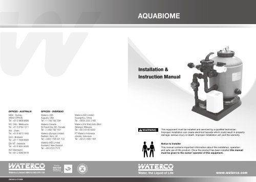
<strong>AQUABIOME</strong><br />
Installation &<br />
Instruction Manual<br />
OFFICES - AUSTRALIA<br />
NSW - Sydney<br />
(HEAD OFFICE)<br />
Tel : +61 2 9898 8686<br />
VIC/ TAS - Melbourne<br />
Tel : +61 3 9764 1211<br />
WA - Perth<br />
Tel : +61 8 9273 1900<br />
QLD - Brisbane<br />
Tel : +61 7 3299 9900<br />
SA/ NT - Adelaide<br />
Tel : +61 8 8244 6000<br />
ACT Distributor<br />
Tel : +61 2 6280 6476<br />
OFFICES - OVERSEAS<br />
<strong>Waterco</strong> USA<br />
Augusta, USA<br />
Tel : +1 706 793 7291<br />
<strong>Waterco</strong> Canada<br />
St-Hyacinthe, QC, Canada<br />
Tel : +1 450 796 1421<br />
<strong>Waterco</strong> (Europe) Limited<br />
Radfield, Kent, UK<br />
Tel : +44(0) 1795 521 733<br />
<strong>Waterco</strong> (NZ) Limited<br />
Auckland, New Zealand<br />
Tel : +64 9 525 7570<br />
<strong>Waterco</strong> (GZ) Limited<br />
Guangzhou, China<br />
Tel : +8620 3222 2180<br />
<strong>Waterco</strong> (Far East) Sdn. Bhd.<br />
Selangor, Malaysia<br />
Tel : +60 3 6145 6000<br />
PT <strong>Waterco</strong> Indonesia<br />
Jakarta, Indonesia<br />
Tel : +62 21 4585 1481<br />
! WARNING<br />
This equipment must be installed and serviced by a qualified technician.<br />
Improper installation can create electrical hazards which could result in property<br />
damage, serious injury or death. Improper installation will void the warranty.<br />
Notice to Installer<br />
This manual contains important information about the installation, operation<br />
and safe use of this product. Once the product has been installed this manual<br />
must be given to the owner/ operator of this equipment.<br />
<strong>Waterco</strong> Limited ABN 62 002 070 733<br />
www.waterco.com<br />
(W23421) 07/2008
Table of<br />
<strong>AQUABIOME</strong><br />
<strong>Waterco</strong> Aquabiome I pg 01<br />
Aquabiome has been engineered specifically for ponds and water gardens. Aquabiome provides<br />
mechanical and biological filtration in a single housing.<br />
<strong>AQUABIOME</strong> ------------------------------------------------- 01<br />
Filtering Pond Water ------------------------------------ 01<br />
A Typical Pond Filter System --------------------------- 02<br />
The Benefits Of Using An Aquabiome ---------------- 03<br />
How Does The Aquabiome Filter Work? --------------- 04<br />
Choosing The Correct Aquabiome For Your Pond ---- 05<br />
Installation Instructions --------------------------------- 06<br />
Starting Up the Aquabiome ----------------------------- 07<br />
Its ability to support dense populations of nitrifying bacteria, its reliability and easy maintenance,<br />
makes Aquabiome especially suitable for high density recirculation systems.<br />
Effective<br />
Excellent Nitrification and Mechanical filtration<br />
Efficient<br />
Hydraulically efficient filter design, balanced slotted laterals to maximize water flow and filtration.<br />
Durable<br />
Corrosion resistant and UV stabilised for outdoor installation.<br />
Air-Backwash<br />
Air assisted hydraulic backwash, saving time and water.<br />
Superior Quality<br />
Aquabiome fibreglass filters embody the latest in fibreglass winding technology.<br />
Backwashing Procedure for the Aquabiome ---------- 08<br />
IMPORTANT NOTES ---------------------------------------- 09<br />
Filtering Pond Water<br />
To maintain good water clarity and a safe environment for fish, the pond water requires a combination<br />
of the following features:<br />
1. Mechanical Filtration<br />
2. Biological filtration<br />
3. U.V. Sterilisation<br />
4. Good circulation<br />
5. Aeration<br />
In simple terms, the ‘mechanical filtration’ is basically straining the water, separating the solids<br />
from the liquid. The solid matter in a pond is usually made up from different forms of debris, which<br />
maybe found at any level in the water. The presence of these solids and suspended particles will<br />
make the pond water appear murky or cloudy, making it difficult for visual inspection of the fish.<br />
The water clarity may not necessarily be a problem to the fish, provided the debris and suspended<br />
solids are of a non-harmful nature.
<strong>Waterco</strong> Aquabiome I pg 03<br />
However, some of the debris in a pond can create problems for the fish, often caused by Ammonia,<br />
which is produced by faecal, mucus, and other decaying matter. To overcome the build up of harmful<br />
Ammonia in the pond water, it is necessary install a ‘Biological filter’. Most often, a Biological filter<br />
is a large chamber full of media, which breeds and cultures ‘good bacteria’. Within the Biological<br />
filter, the good bacteria consume and convert the harmful Ammonia into harmless Nitrate.<br />
Conventional pond filtration systems generally keep the mechanical and Biological filtration aspects<br />
separate, and as such the equipment involved can be rather large and bulky. In addition to the size<br />
considerations, most conventional filter systems may require a high degree of maintenance and<br />
cleaning. This can prove to be very time consuming particularly during the summer months, when<br />
the frequency of cleaning can be so often, it becomes impractical.<br />
Combined with the Mechanical and Biological filtration, it is essential that the pond water is recirculated<br />
(turnover time) at a rate of every: 2 – 3 hours.<br />
A Typical Pond Filter System<br />
Most basic conventional Pond filter systems employ a stage process, which may comprise of the<br />
following parts.<br />
Whilst the Fourth stage – The Hi Rate sand filter, will work efficiently in removing the remaining<br />
solids down to 7 - 10 microns in size & maintaining water clarity. However a downside in using a<br />
‘pressure sand filter’ is, that it may clog very rapidly (perhaps on a daily basis) which would cause<br />
the need for regular cleaning or backwashing.<br />
The fifth stage – Uses Ultra Violet light to sterilise and for inhibiting the growth of Algae and other<br />
undesired organic matter.<br />
The sixth stage – Aeration for the pond supplied either via a Venturi (and or) a waterfall. A waterfall<br />
can make a very attractive feature in the pond, though it may cool the water, which could inhibit<br />
fish growth.<br />
Any pond filter system must run 24 hours a day – seven days a week!<br />
This is essential to ensure that all aspects of the system work on a continuous basis to ensure a<br />
safe and healthy environment for the fish to live.<br />
Therefore, a major consideration for the pond owner is the power and water consumption used to<br />
maintain the pond filtration. Usually, Hi Rate sand filters need a fairly powerful pump to force the<br />
water through the fine sand, and this can prove expensive when running on a continuous basis.<br />
Likewise, the frequency of backwashing will lead to a large volume of water being required. This<br />
too can prove costly in the long run.<br />
(i) First stage - Sedimentation chamber or Vortex<br />
(ii) Second stage - Aeration for Biological filters<br />
(iii) Third stage - Biological chamber filter<br />
(iv) Fourth stage - Hi Rate sand filter<br />
(v) Fifth stage - U.V. Sterilisation<br />
(vi) Sixth stage - Venturi or waterfall<br />
In a filter system of the above type, the first stage can be a simple chamber with baffle plates, or<br />
a more sophisticated Vortex chamber, which will remove between 50 – 70% of the solid waste<br />
matter.<br />
The second stage would be air supplied by a simple air pump and air stone, injecting the air directly<br />
into the water flowing through the Biological filters. The Oxygen provided will enhance the life and<br />
growth of the bacteria colonies assisting with the removal of Ammonia.<br />
The Benefits Of Using An Aquabiome<br />
The principal of using an Aquabiome is to combine the Biological filtration aspect with the<br />
mechanical filtration (water polishing).<br />
By combining these two filtration aspects (mechanical & Biological), using an Aquabiome, the<br />
whole system can be more compact than a traditional - conventional pond filter system. Or, the<br />
Aquabiome can also be used to enhance an existing system. In addition, the Aquabiome requires<br />
far less pressure than a conventional Hi Rate sand filter, therefore the type of pump needed will<br />
require far less power. Possibly reducing power use by 50%!<br />
Perhaps most important of all, an Aquabiome will require far less maintenance – cleaning or back<br />
washing than a typical Hi Rate pressure sand filter. This will mean you could save a considerable<br />
amount of wasted water and time, whilst keeping your pond in ‘tip top condition!<br />
The third stage can comprise of several media types and may assist in clearing another 15 – 20%<br />
of the debris, though these filters can be very difficult to clean.
<strong>Waterco</strong> Aquabiome I pg 05<br />
How Does The Aquabiome Filter Work?<br />
The Aquabiome should be installed after your strainer/Vortex and main biological filter system.<br />
A suitably sized pump must be selected to ensure the correct water flow is delivered to the<br />
Aquabiome. Once installed, the Aquabiome will remove suspended solids down to 10 microns in<br />
size, maintaining your water clarity to a very high standard.<br />
The pumped water is fed to the Multi-port valve and diverted to the lower filter inlet. The inflowing<br />
water is evenly dispersed through the special slotted pipes (Laterals) within the lower section of<br />
the filter. The contaminated water flows upwards through the filter vessel depositing waste matter<br />
between the crevices of the Biomedia.<br />
To assist the growth of Bacteria for removal of the Ammonia present in the contaminated inflowing<br />
water, you will need to charge the system with: ‘Filter Start’. Once added to the inflowing water,<br />
good bacteria will begin to colonise on the filter media enhancing the biological action.<br />
The Aquabiome is designed to reduce the amount of maintenance (and waste water) required<br />
and ideally if the equipment has been correctly sized, backwashing will only be required on a<br />
weekly basis. The backwashing process is assisted by the use of a very powerful blower (air<br />
compressor) and the whole procedure will take less than 5 minutes to perform. (See general running<br />
instructions).<br />
The Aquabiome is designed to ensure servicing simplicity. The main filter body has a large 8”<br />
diameter lid for easy access to the internals of the filter. Both the top collector assembly and<br />
laterals can be easily unscrewed and removed for cleaning.<br />
Choosing The Correct Aquabiome For Your Pond<br />
Aquabiome ASM400 ASM500 ASM600 ASM750 ASM900<br />
Nominal Diameter<br />
mm / inch<br />
Filter Surface Area<br />
m2 / ft2<br />
Media Volume litres /<br />
gallons<br />
400 / 16 500 / 20 600 / 24 750 / 30 900 / 35<br />
0.13 / 1.4 0.2 / 2.1 0.3 / 3.2 0.44 / 4.9 0.64 / 7.15<br />
43 / 11.3 68 / 18 117 / 30.9 199 / 52.6 303 / 80<br />
Media Weight kg / lbs 21.5 / 5.7 34 / 9 58.5 / 15.45 99.5 / 26.3 151.5 / 40<br />
Biofilter Surface Area<br />
m2 / ft2<br />
Inlet / Outlet<br />
Connections<br />
Min - Max Flow Rate<br />
47.3 / 509 74.8 / 805 128.7 / 1385 218.9 / 2356 333.3 / 3588<br />
40mm/ 50mm<br />
[EU] / 1 1 /2”<br />
40mm/ 50mm<br />
[EU] / 1 1 /2”<br />
40mm/ 50mm<br />
[EU] / 1 1 /2”<br />
50mm / 63mm<br />
[EU] / 2”<br />
50mm / 63mm<br />
[EU] / 2”<br />
lpm 52 - 101 80 - 157 120 - 226 180 – 353 255 - 509<br />
m3/hr 3.1 – 6.1 4.8 – 9.4 7.2 – 13.5 10.8 – 21.2 15.3 – 30.5<br />
gpm 13.7 – 26.7 21.1 – 41.5 31.7 – 59.7 47.6 – 93.3 67.4 – 134.5<br />
Max Pond Size litres /<br />
gallons<br />
Feed Rate kg / lbs<br />
per day<br />
Total Ornamental Fish<br />
weight* kg / lbs<br />
Total Aquaculture<br />
Fish weight* kg / lbs<br />
Tank Diameter mm /<br />
inch<br />
Overall Height mm<br />
/ inch<br />
13,000 / 3,434 20,000 / 5,300 36,000 / 9,500 60,000 / 15,900 90,000 / 24000<br />
0.32 / 0.71 0.5 / 1.1 0.9 / 1.98 1.5 / 3.31 2.4 / 5.29<br />
10.7 / 23.6 16.7 / 36.8 30 / 66.1 50 / 110.2 80 / 176.4<br />
32 / 70.5 50 / 110.2 90 / 198 150 / 330.7 240 / 529<br />
421 / 16.5” 520 / 20.5” 622 / 24.5” 772 / 30.4” 923 / 36.3”<br />
856 / 33.7” 815 / 32.1” 880 / 34.6” 993 / 39.1” 1115 / 43.9”<br />
Valve Size mm / inch 40 / 1 1 /2” 40 / 1 1 /2” 40 / 1 1 /2” 50 / 2” 50 / 2”<br />
Bed Depth mm / inch 290 / 11.4” 290 / 11.4” 360 / 14.2” 400 / 15.7” 440 / 17.3”<br />
* Maximum fish stocking weight depends on the percentage of body weight fed daily.<br />
• Ornamental fish weight based on feeding rate of 3% of body weight.<br />
• Aquaculture fish weight based on feeding rate of 1% of body weight.
<strong>Waterco</strong> Aquabiome I pg 07<br />
Installation Instructions:<br />
1. Prior to installation: Prepare an area large enough to stand all the equipment allowing adequate<br />
space for connecting pipe-work and routine servicing. Once you have decided on the optimum<br />
position, prepare a flat and level concrete base to accommodate the unit.<br />
2. Remove filter – Air blower and pipe-work from packaging. Check to ensure all parts are present<br />
and are in good condition.<br />
3. Place the main filter unit on the pre-prepared concrete base making sure that both the blower<br />
and the filter vessel are secure.<br />
4. Connect the Multi-port valve onto the top and bottom bulkheads, ensuring that the ‘O’ rings are<br />
in place. Tighten the connecting unions by hand only.<br />
5. Connect the Non Return Valve unit between the Multi-port Valve and the blower unit ensuring<br />
that all ‘O’ rings are in position. Tighten the connecting unions by hand only.<br />
13. Once all glued pipe connections have been completed, ensure adequate time for the adhesive<br />
to dry. Most likely this will be at least 12 hours.<br />
14. IMPORTANT! Ensure the pipe-work and glued joints have had adequate time to vent any<br />
toxic (or flammable) fumes, before starting the air blower. Ideally, run the water pump for<br />
at least an hour before testing the blower on the system.<br />
15. IMPORTANT! The electrical connection of the blower must be made by a qualified<br />
electrician, and in accordance with local regulations. The blower unit must be protected<br />
by an RCD - residual current device.<br />
16. Remove the main filter lid, then, unscrew the top collector assembly. Check to ensure all the<br />
Laterals are securely in place in the bottom of the filter.<br />
17. Ensure you have the correct amount of media as stated in the table above in section 5 –<br />
Specifications. Carefully pour in the media into the filter avoiding any spillages. Once the whole<br />
amount is in the filter, re fit the collector unit and then, the main filter lid.<br />
6. Connect the waste - water sight glass assembly to the waste connection of the Multi-port valve<br />
(on LHS) ensuring that the ‘O’ rings are in place. Tighten the connecting unions by hand only.<br />
7. Connect the isolator valve unit to the main Multi-port valve (RHS) ensuring that ‘O’ rings are in<br />
place. Tighten the connections by hand only.<br />
8. Screw on the return union to the remaining position (on the lower - RHS) of the Multi-port valve.<br />
Tighten the connection by hand only.<br />
9. Use PTFE tape around the threads of the pressure gauge and screw into the threaded hole on<br />
the side of the Multi-port valve. There are two positions for this, so install the gauge to the most<br />
easy to see position and use the screw cap in the opposite hole. Be sure NOT to over tighten<br />
the pressure gauge as this will damage the threads!<br />
10. Cut and glue pipe-work from your pump discharge to the small isolator valve already fitted<br />
as described in item 7 above. Be sure not to stress any pipe-work by providing suitable<br />
supports, where required.<br />
NOTE: All pipe-work connections are BSP – ABS Pipe-work.<br />
Ensure you use compatible adhesive and pipe!<br />
11. Cut and glue pipe-work between the waste line sight glass unit and the drain, again ensuring<br />
that all pipe-work is well supported.<br />
12. Cut and glue pipe-work between the return union on the Multi-port valve and the pipe-work<br />
back to the pond. This return line may include a U.V. light system, but again ensure all pipework<br />
is supported.<br />
Starting Up The Aquabiome<br />
1. Re-check all threaded connections to ensure they are watertight and select ‘Filter’ mode on the<br />
Multi-port valve.<br />
2. Select the open position of the isolator valve, this will be when the white arrow is pointing to<br />
12pm position and the handle is across the pipe-work.<br />
3. Ensure system water level is to correct level and start the main circulating pump. Water will<br />
begin to flow through the filter, which should be observed at the top of the vessel within a few<br />
moments. With the filter and valves in this position, the filter is working in it’s normal – Filter<br />
mode.<br />
4. Once the unit has been run for a while, check all joints to ensure there are no leaks. To check<br />
that the blower is functioning correctly, follow the backwash procedure as stated below.<br />
5. Once all parts of the system have been tested, add some ‘filter start’ to prime the filter for<br />
biological growth. (Consult your dealer).
<strong>Waterco</strong> Aquabiome I pg 09<br />
Backwashing Procedure For The Aquabiome<br />
1. Turn the circulating pump off.<br />
IMPORTANT NOTES:<br />
Never try to run the Blower and the circulating pump at the same time!<br />
2. Select 3pm position on the isolator valve (handle in line with pipe).<br />
3. Select Rinse position on the Multi-port Valve.<br />
4. Ensure waste line is unobstructed and the circulation pump is NOT switched on! Switch<br />
blower unit on and run for 2.5 – 3 minutes. This will agitate the media causing the entrapped<br />
debris to disperse into the available water within the filter. Some of the contaminated water will<br />
discharge to waste. Switch blower off.<br />
5. Keep the Multi-port valve in rinse mode, but alter the position of the isolator valve back to the<br />
12pm position.<br />
6. Switch the circulation pump on and run for 2 – 3 minutes, during this time dirty water will<br />
discharge eventually clearing. Switch pump off.<br />
7. Select backwash mode on the Multi-port valve. Run the circulation pump for 30 – 40 seconds.<br />
This will remove any remaining debris. Switch pump off.<br />
8. Select filter mode on the Multi-port valve and continue to filter as normal.<br />
(Fig 1) (Fig 2)<br />
Regularly check the 3mm vent hole on the Blower pipe ‘T’ to ensure it is unobstructed allowing<br />
moisture to drain from the unit. (Fig 1)<br />
Regularly check the Non return valve to ensure water is not bypassing, which could cause<br />
the blower to flood. (Fig 2)