Delta UV : installation and instruction manual
Delta UV : installation and instruction manual
Delta UV : installation and instruction manual

Create successful ePaper yourself
Turn your PDF publications into a flip-book with our unique Google optimized e-Paper software.
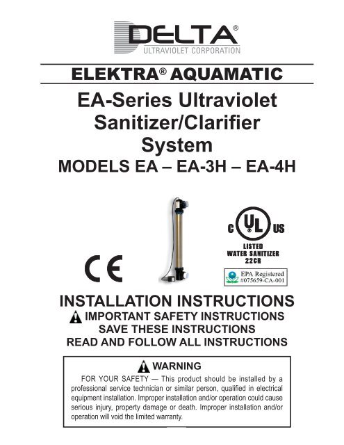
ELEKTRA ® AQUAMATICEA-Series UltravioletSanitizer/ClarifierSystemMODELS EA – EA-3H – EA-4HINSTALLATION INSTRUCTIONSIMPORTANT SAFETY INSTRUCTIONSSAVE THESE INSTRUCTIONSREAD AND FOLLOW ALL INSTRUCTIONSWARNINGFOR YOUR SAFETY — This product should be installed by aprofessional service technician or similar person, qualifi ed in electricalequipment <strong>installation</strong>. Improper <strong>installation</strong> <strong>and</strong>/or operation could causeserious injury, property damage or death. Improper <strong>installation</strong> <strong>and</strong>/oroperation will void the limited warranty.1
INSTRUCTIONS PERTAINING TORISK OF FIRE, ELECTRIC SHOCKOR INJURY TO PERSONWARNING — When using this unit, basic precautions should always betaken, including the following:1. READ AND FOLLOW ALL INSTRUCTIONS.2. DANGER: To avoid possible electrical shock, special care should be takensince water is employed in the use of this equipment. For each of thefollowing situation, do not attempt repairs yourself; return the applianceto an authorized service facility or the manufacturer for service or discardthe appliance.A. If the appliance falls into the water, DO NOT reach for it! Firstunplug it <strong>and</strong> then retrieve it. If electrical components get wet (notthe electrical housings, but the components themselves), unplugthe appliance immediately.B. Do not operate any appliance if it has a damaged cord or plug, orif it is malfunctioning or if it is dropped or damaged in any manner.3. Always unplug an appliance from an outlet when not is use, before puttingon or taking off parts <strong>and</strong> before cleaning. Never yank the cord to pull theplug from the outlet. Grasp the plug <strong>and</strong> pull it to disconnect it.4. Do not use an appliance for anything other than its intended use. The useof attachments not recommended or sold by the appliance manufacturermay cause an unsafe condition.5. This unit contains an ultraviolet bulb that can cause discomfort or irritationto the eyes if viewing while operating. Prolonged exposure to the eyescan cause blindness. DO NOT VIEW <strong>UV</strong> BULB WHILE OPERATING ORDURING MAINTENANCE.6. Read <strong>and</strong> observe all of the important notices in these <strong>instruction</strong>s <strong>and</strong>on the appliance.7. If an extension cord is necessary, a cord with a proper rating <strong>and</strong> suitablefor outdoor use should be used. A cord rated for less amperes or wattsthan the appliance’s rating may overheat. Care should be taken to arrangethe cord that it will not be tripped over or pulled loose.8. This product shall only be connected to a power supply receptacle orconnection protected by a Ground Fault Circuit Interrupter (GFCI).9. Protect this unit from direct prolonged sunlight exposure.10. ENVIRONMENTAL NOTICE - Hg-Lamp CONTAINS MERCURY. Manage inaccordance with disposal laws. See: www.lamprecycle.orgSAVE THESE INSTRUCTIONS2
SAVE THESE INSTRUCTIONSINSTALLATION INSTRUCTIONSWARNINGWhen using electrical products, basic precautions should alwaysbe followed, including the following:1. DANGER: RISK OF ELECTRIC SHOCK. Connect only to a circuitprotected by a Ground Fault Circuit Interrupter.2. Grounding is required. The unit should be installed <strong>and</strong> grounded by aqualified service representative.3. Install to permit access for servicing.IMPORTANT: Follow the <strong>instruction</strong>s EXACTLY <strong>and</strong> IN THE ORDERLISTED. Once installed, your <strong>UV</strong> unit will provide years of successfuloperation.TABLE OF CONTENTS0.0 Forward1.0 Introduction2.0 Pre-Installation2.1 Pond Turnover Rates2.2 Swimming Pool Turnover Rates2.3 Spa Turnover Rates3.0 Desired Flow Rate Chart – Swimming Pools, Fountains, Water Features4.0 Desired Flow Rate Chart – Ponds5.0 Installation5.1 Locating The <strong>UV</strong> Unit5.2 Plumbing The <strong>UV</strong> Unit – Plumbing Diagram <strong>and</strong> Bypass Diagram5.3 Installing Inlet/Outlet Unions5.4 Installing Mounting Legs5.5 Mounting The <strong>UV</strong> Unit On A Solid Base5.6 Gluing Piping To The <strong>UV</strong> Unit5.7 Electrical Connection5.8 Electrical Bonding (Grounding)5.9 Electrical Interlock Of Pump/EA Unit6.0 Start-up6.1 Pump Start-up6.2 Leak Check Total System6.3 Swimming Pool/Spa Chemical Balance7.0 Maintenance – Quartz Tube Assembly Maintenance/Removal7.1 Disconnect Power7.2 Stop Circulation Pump3
7.3 Remove Plastic Electrical Tee Fitting7.4 Cleaning Quartz Tube7.5 Re-installing Quartz Tube Assembly8.0 <strong>UV</strong> Bulb Removal/Replacement8.1 Electrical Connector Assembly Removal8.2 Removing The <strong>UV</strong> Bulb8.3 Removing The Bulb Cushion <strong>and</strong> O-Rings9.0 <strong>UV</strong> Bulb Installation9.1 Seating Bulb End Cushion9.2 Installing O-Rings On Bulb End9.3 Connecting Bulb Pins To Bulb Connector9.4 Inserting Bulb Into Quartz Tube9.5 Turning On the Circulation Pump9.6 Plugging The Unit Into The Power10.0 Maintenance – Scheduled Bulb Replacement10.1 Annual Reminder11.0 Additional <strong>UV</strong> Unit Maintenance12.0 Normal Operating Results12.1 Ponds12.2 Swimming Pools, Spas, Fountains, Water Features, Waterfalls13.0 Winterizing13.1 Freeze Damage13.2 Freezing Weather Precautions14.0 Swimming Pool Chemicals15.0 How To Obtain Service16.0 Parts Schematic <strong>and</strong> Part Numbers17.0 Frequently Asked Questions17.1 Salt Water Use17.2 Filter Cleaning17.3 Time Clock Operation17.4 Residual Effect From <strong>UV</strong>17.5 Horizontal Mounting Of <strong>UV</strong> Unit17.6 Below Water Installation17.7 Multiple <strong>UV</strong> Units For Larger Installations17.8 GFCI (Ground Fault Circuit Interrupter) Necessity18.0 Troubleshooting18.1 <strong>UV</strong> Bulb Will Not Light At Startup18.2 <strong>UV</strong> Bulb Was Lit, But Is Not Lit Now18.3 <strong>UV</strong> Bulb Stays Lit When Pump Is Off18.4 Water Is Green18.5 GFCI Trips18.6 Unit Makes Noise When Operating18.7 Water Leaks From Electrical Enclosure19.0 Specifications4
0.0 Forward: The <strong>Delta</strong> <strong>UV</strong> Elektra ® Aquamatic <strong>UV</strong> Unit is designed for use in swimming pools, spas, fountains,water features, waterfalls <strong>and</strong> fish ponds. It is not designed for use in potable (drinking) water <strong>installation</strong>s.Use of this product in applications other than those indicated above will void your warranty <strong>and</strong> could beharmful to your health or the health of others.1.0 Introduction - How The Elektra ® Aquamatic <strong>UV</strong> Unit Works: Within the Elektra ® Aquamatic <strong>UV</strong> Unit (whichwe will refer to throughout this <strong>manual</strong> as EA), a high intensity electrically operated Ultraviolet (<strong>UV</strong>) bulb is locatedinside the unit’s wet chamber. This <strong>UV</strong> bulb gives off Ultraviolet light wave emissions when lit. The bulb’s operatingemission range is within the Ultraviolet light wave spectrum at 253.7 nm of wavelength. This wavelength is such thatwhen bacteria, protozoa, viruses, algae spores, or other single celled waterborne microorganisms in the incomingwater flow are exposed to the light waves of the <strong>UV</strong> bulb for a proper period of time, the DNA of the microorganismis altered or disrupted <strong>and</strong> this controls <strong>and</strong> eradicates these unwanted contaminates <strong>and</strong> renders them harmless.Your EA <strong>UV</strong> unit has been sized to produce these important <strong>UV</strong> rays in the same intensity as is required for Class Apotable drinking water, which is 30 microwatts/sec/cm 2 .While you may see lesser competitive units of similar vessel size claiming to work on larger ponds or pools, youwill find that these units do not operate at the same high intensity as does the EA unit <strong>and</strong> are unable to obtain thesame level of killing power as the EA unit. Rely on the flow chart shown herein for proper maximum killing power unitselection for your application.Pond, spa or pool water containing these unwanted contaminates enters the EA unit’s wet chamber <strong>and</strong> is exposedto the light rays generated by the <strong>UV</strong> bulb. The EA unit has been designed to allow for some turbidity in the water, asturbidity will reduce the <strong>UV</strong> light wave transmission capability. Therefore, all EA units are sized to allow for possibleturbidity in the water <strong>and</strong> the reduction in the killing power of the <strong>UV</strong> bulb when it nears the end of its useful life. Whenthe incoming water is exposed to the bulb for the proper duration <strong>and</strong> intensity, the water exiting the unit is near drinkingwater biological quality. CAUTION!: THIS UNIT IS FOR POND, SPA, WATER FEATURE, FOUNTAIN OR POOL USEONLY. DO NOT USE THIS UNIT FOR POTABLE (DRINKING) WATER SANITIZATION.2.0 Pre-Installation - In order to ensure that your EA unit functions with the proper exposure time to achieve the desiredwater sanitization, it is important to provide the proper water flow rate through the EA unit. If water passes through theunit too quickly, the exposure time of the microorganisms to the <strong>UV</strong> bulb produced rays will not be sufficient to obtainthe desired kill rate. The water flow rate through the <strong>UV</strong> unit is governed by the piping of your vessel, pool or pond <strong>and</strong>the size <strong>and</strong> output of your circulation pump. There also needs to be consideration to the application for the <strong>UV</strong> unit.Fish ponds have different requirements than do swimming pools, spas, water features, fountains, or waterfalls.2.1 Pond Turnover Rates - Most fish pond experts agree that there is no set formula for the sizing of circulationpumps <strong>and</strong> <strong>UV</strong> systems for ponds. The size of the pond, the depth, plant coverage, the amount of sun exposureor shade, <strong>and</strong> the number of fish in the pond all contribute to determining what the flow rate for a pond shouldbe. The best advise is to consult with a pond expert to determine what the flow rate for your pond should be.This is the best method of ensuring that your pond is being circulated properly. But absent of that, a generalrule of thumb that can be used for ponds is that the water volume of the pond should be passed through thefilter system every two hours or so. Thus, if you take the volume of your pond (in gallons), <strong>and</strong> divide that by120 (the number of minutes in two hours) you will have an approximate desired flow rate for your pond. Then,you select a pump <strong>and</strong> filter system that works properly at that flow rate. As an example, a 6000 gallon pondwould have a desired flow rate of 50 gallons per minute (GPM) calculated at 6000 /120 = 50.2.2 Pool Turnover Rates - Swimming pools are somewhat simpler to calculate for flow rates. Most residentialpools are designed to have the capacity of the pool turned over every 12 hours. Semi-commercial pools arenormally designed for an 8 hour turnover flow rate. Check with your local jurisdiction for the required flow ratefor your type of pool to be sure. As an example, using the same formula as above, a 20,000 gallon residentialpool will need to have a pump capable of a 28 GPM flow rate <strong>and</strong> a 25,000 gallon semi-commercial pool willneed to have a pump capable of 52 GPM.Like pools <strong>and</strong> ponds, the EA unit needs to be properly sized by flow rate. Moving the water through the EAunit’s wet chamber too fast will not allow enough exposure time of the water to be exposed to the <strong>UV</strong> bulb rays.The following charts show the desired <strong>and</strong> maximum flow rates for your EA unit. Make sure the flow rate of yourcirculation system pump does not exceed the maximum allowable flow rate of the <strong>UV</strong> unit you have selected.(Consult your supplier or pump manufacturer for the pump’s GPM rating if you are in doubt.) If the pump outputexceeds the maximum flow rate of the EA unit you have selected, select an EA model with a higher flow rate5
capacity rating or consider a multiple unit <strong>installation</strong>. If your application exceeds the maximum flow rates forthe EA-4H-40, multiple units can be used, or you can install a larger capacity <strong>Delta</strong> E/ES or EP series unit. Inmost instances a larger capacity unit is more cost effective than multiple units. Contact your supplier or <strong>Delta</strong><strong>UV</strong> for information on these larger capacity <strong>UV</strong> sanitizers. (See Sec. 17.7).2.3 Spa Turnover Rates - Spas also require proper flow through the <strong>UV</strong> system. Flow rates of the spa circulationpump should not exceed the maximum flow rate for the <strong>UV</strong> system selected. Excessive flow rates through the<strong>UV</strong> system will render the system ineffective. This holds for all applications. Never exceed the flow rate throughthe <strong>UV</strong> system as noted on brochures <strong>and</strong> data sheets.3.0 Desired <strong>UV</strong> Unit Flow Rates - Swimming Pools, Fountains, Water Features<strong>Delta</strong> <strong>UV</strong> Maximum Maximum Max Pool Volume Max Pool Volume Max Pool Volume Max Pool VolumeEA Flow Rate Flow Rate 12 Hr. Turnover 12 Hr. Turnover 8 Hr. Turnover 8 Hr. TurnoverModel (GPM) (LPM) (Gallons) (Liters) (Gallons) (Liters)EA-9 6 23 4320 16353 2880 10902EA-18 9 34 6480 24529 4320 16353EA-26 15 57 10800 40882 7200 27255EA-40 23 87 16560 62686 11040 41791<strong>Delta</strong> <strong>UV</strong> Maximum Maximum Max Pool Volume Max Pool Volume Max Pool Volume Max Pool VolumeEA-3H Flow Rate Flow Rate 12 Hr. Turnover 12 Hr. Turnover 8 Hr. Turnover 8 Hr. TurnoverModel (GPM) (LPM) (Gallons) (Liters) (Gallons) (Liters)EA-3H-5 16 60 11520 43200 7680 28800EA-3H-10 33 125 23760 90000 15840 60000EA-3H-20 46 174 33120 125280 22080 83520EA-3H-40 52 197 37440 141840 24960 94560<strong>Delta</strong> <strong>UV</strong> Maximum Maximum Max Pool Volume Max Pool Volume Max Pool Volume Max Pool VolumeEA-4H Flow Rate Flow Rate 12 Hr. Turnover 12 Hr. Turnover 8 Hr. Turnover 8 Hr. TurnoverModel (GPM) (LPM) (Gallons) (Liters) (Gallons) (Liters)EA-4H-5 21 80 15120 57600 10080 38400EA-4H-10 44 167 31680 120240 21120 80160EA-4H-20 61 231 43920 166320 29280 110880EA-4H-40 69 261 49680 187920 33120 12580Note: Multiple units can be used for flow rates beyond those specified herein. (See Sec. 17.7)4.0 Desired <strong>UV</strong> Unit Flow Rates - Ponds<strong>Delta</strong> <strong>UV</strong> Maximum Maximum Max Volume Max Volume Max Volume Max VolumeEA Flow Rate Flow Rate 2 Hr. Turnover 2 Hr. Turnover 3 Hr. Turnover 3 Hr. TurnoverModel (GPM) (LPM) (Gallons) (Liters) (Gallons) (Liters)EA-9 6 23 720 2725 1080 4088EA-18 9 34 1080 4088 4320 16353EA-26 15 57 1800 6814 7200 27255EA-40 23 87 2760 10448 11040 41791<strong>Delta</strong> <strong>UV</strong> Maximum Maximum Max Volume Max Volume Max Volume Max VolumeEA-3H Flow Rate Flow Rate 2 Hr. Turnover 2 Hr. Turnover 3 Hr. Turnover 3 Hr. TurnoverModel (GPM) (LPM) (Gallons) (Liters) (Gallons) (Liters)EA-3H-5 16 60 1920 7200 2880 10800EA-3H-10 33 125 3960 15000 5940 22500EA-3H-20 46 174 5520 20880 8280 31320EA-3H-40 52 197 6240 23640 9360 354606
<strong>Delta</strong> <strong>UV</strong> Maximum Maximum Max Volume Max Volume Max Volume Max VolumeEA-4H Flow Rate Flow Rate 2 Hr. Turnover 2 Hr. Turnover 3 Hr. Turnover 3 Hr. TurnoverModel (GPM) (LPM) (Gallons) (Liters) (Gallons) (Liters)EA-4H-5 21 80 2520 9600 3780 14400EA-4H-10 44 167 5280 20040 7920 30060EA-4H-20 61 231 7320 27720 10980 41580EA-4H-40 69 261 8280 31320 12420 46980Note: Multiple units can be used for flow rates beyond those specified herein. (See Sec. 17.7)5.0 Installation - Before starting the <strong>installation</strong>, PLEASE read this <strong>manual</strong> from cover to cover. A few momentsspent initially becoming totally familiar with the EA unit <strong>and</strong> its <strong>installation</strong> requirements will save a great deal oftime (<strong>and</strong> expense) later. If you have questions that are not answered after you have completed the reading of this<strong>manual</strong>, contact your supplier or <strong>Delta</strong> <strong>UV</strong>. We are ready to assist you at anytime <strong>and</strong> we want your <strong>installation</strong>to go smoothly <strong>and</strong> the equipment to work properly.5.1 Locating the <strong>UV</strong> Unit - Once you have confirmed the size of your pond or pool <strong>and</strong> compared that informationagainst the requirements of your EA <strong>UV</strong> unit by using the charts above, it is now time to install your unit. The EAunit comes with all internal components fully assembled <strong>and</strong> ready for <strong>installation</strong>. Only the Inlet/Outlet unions<strong>and</strong> (if used) stainless steel mounting legs need to be installed to ready your unit for <strong>installation</strong>. The housingof the EA <strong>UV</strong> unit is stainless steel <strong>and</strong> the black inlet <strong>and</strong> outlet ends are <strong>UV</strong> inhibited ABS plastic. Your unitwill function fine in the outdoors. Installing the EA unit indoors or inside a covered area is preferred however,to keep your unit looking new. The EA unit will need to be powered from a 120V/15A electrical outlet. (240V50/60HZ EA units are available.) If the electrical outlet is outdoors <strong>and</strong> exposed to the weather, it will need tobe an Outdoor type receptacle. The EA unit comes with a five foot (minimum) (1.5 meter) long power cord.Do not use an extension cord unless it is at least a 16/3 size conductor waterproof type <strong>and</strong> is no more thantwenty-five feet (7.5 meters) long.5.2 Plumbing the <strong>UV</strong> Unit - Your EA unit will need to be plumbed into your pond, spa or swimming poolcirculation system. The diagram (Fig. 1) shows how the unit is to be plumbed. Note that the water is to be pipedfrom the pressure side of the pump <strong>and</strong> after the filter, in <strong>and</strong> out of the EA unit. When the EA unit is in a verticalposition, the inlet for the water is at the bottom of the EA unit, <strong>and</strong> the outlet is at the top of the EA unit. The EAunit may also be mounted in a horizontal position <strong>and</strong> in that instance, water can enter <strong>and</strong> exit from either endof the unit. If your pump exceeds the maximum flow rate of the EA unit, <strong>installation</strong> of a plumbing by-pass willbe necessary to bypass some of the pump’s flow around the EA unit so the maximum flow rate of the EA unitwill not be exceeded. A typical bypass arrangement is shown in Fig. 2. (NOTE: A bypass system will allow onlythe water that passes through the EA unit to be sanitized. Therefore, a by-pass should be used only to bypass avery small amount of water <strong>and</strong> the main flow should be through the EA unit itself for maximum killing power.)5.3 Installing Inlet/Outlet Unions - The EA unit comes with union nuts installed on the housing. Packed withyour EA unit are the remaining components necessary to complete the Inlet/Outlet unions. The clear union tailpiece is used on the water outlet union, <strong>and</strong> the solid color union tail piece is used on the bottom inlet union.Also packed with your EA unit are two rubber-like gaskets that are used to complete the Inlet/Outlet unions.One side of the gasket is flat, the other side has a half round bead on the face. The two PVC unions each havea groove in the face of the union tail piece <strong>and</strong> that groove accepts the half-round bead of the gasket to holdthe gasket in place correctly. Place the gaskets into the face of the union tail pieces. Now, install the uniontail pieces by screwing them into the union nuts on the EA unit. DO NOT OVERTIGHTEN. H<strong>and</strong> tightening issufficient. OVERTIGHTENING WILL BREAK THE UNION NUTS.5.4 Installing the Mounting Legs - Your EA unit comes with two stainless steel mounting legs <strong>and</strong> two stainlesssteel b<strong>and</strong> clamps. The legs can be used to mount the EA unit to a solid surface, such as a wall or the floor. Asthe EA unit is not heavy, it can also be mounted directly to the rigid PVC plumbing of your pool, spa or pond.If the mounting legs are used, it is recommended that the b<strong>and</strong> clamps be placed over each plastic end of theEA unit, rather than over the stainless steel housing, to facilitate removal of the stainless steel housing withoutrequiring removal of the unit’s plastic ends. The stainless steel housing has two unions to allow the inlet <strong>and</strong> outletto be rotated for plumbing convenience. Each end of the EA unit can be rotated 360 degrees to accommodatethe piping from any angle of approach.7
ELEKTRA AQUAMATIC <strong>UV</strong>ELEKTRA AQUAMATIC <strong>UV</strong>HEATER(POOLS)VALVEVALVEFILTERVALVEPUMPVALVEFLOW METER(OPTIONAL)VALVEFIG. 1TYPICAL POOL & POND INSTALLATIONFIG. 2TYPICAL BYPASS SYSTEM5.5 Mounting the EA Unit on a Solid Base - The next step is to secure the EA unit for operation. As mentionedbefore, either the piping itself or the two mounting legs can be used to secure the EA unit in place. FAILURE TOPROPERLY SECURE THE UNIT MAY CAUSE NOISE DUE TO VIBRATION CAUSED BY WATER PASSINGTHROUGH THE WET CHAMBER.5.6 Gluing Circulation Piping - The Inlet/Outlet PVC union tail pieces are 2 inch pipe size (63mm for overseasmodels). Your PVC supply piping should be glued into the union tail pieces using an appropriate PVC primer<strong>and</strong> PVC cement, as recommended by your supplier. Inlet piping should be supported <strong>and</strong> should not rest solelyupon the unions, to avoid breaking the unions. The <strong>installation</strong> of valves on the inlet <strong>and</strong> outlet lines attachedto the <strong>UV</strong> unit is recommended for future servicing. If the EA unit is located with any portion of the unit belowthe surface of the pond or pool, then VALVES ARE MANDATORY, so you may winterize or remove the EA unitwithout draining your pool, spa or pond. When you have completed the piping <strong>installation</strong> (including bypass ifnecessary), the final step is to plug the unit into its power source.5.7 Electrical Connection - The electrical power rating for your EA unit is shown on the label on the outsideof the unit. US <strong>and</strong> Canadian EA units operate on 120V/50/60 Hz – (.750 Amps maximum). This extremely lowpower consumption makes operating your EA unit very economical. Therefore, you will need a 15 Amp 120Vreceptacle for your EA unit to plug into. (Check the label on your overseas unit for its power requirement.) YourEA unit is supplied with an five foot long (1.5 meter) long weatherproof power cord terminating in either a 3-pronggrounded NEMA plug. The plug assembly contains the electrical ballast that operates the <strong>UV</strong> bulb in the EAunit. In the US or Canada it is m<strong>and</strong>atory that you install a GFCI in the electrical outlet or in the breaker panelserving the EA unit power receptacle. NOTE: Should the electrical power cord of your EA unit become frayedor damaged in the future, unplug it from the power receptacle <strong>and</strong> replace it immediately.Your EA unit can be exposed to the weather, however you must protect the electrical plug by providing anOutdoor type electrical receptacle to prevent rain <strong>and</strong> such from entering the plug connection. Overseas 240volt EA units are supplied with a separate mounting box that is hard wired into the electrical system.5.8 Electrical Bonding (Grounding) - As required in the US by Article 680, NEC <strong>and</strong> many local electrical codes,all metallic equipment of your pond, spa or swimming pool system must be electrically bonded to a commonbonding grid, using a continuous #8 bare copper wire to connect all components (pump, filter, EA unit) togetherusing the ground lugs supplied with each component. The EA unit has a pressure grounding lug located on thestainless steel housing to accommodate this function. Connect the bonding wire from the bonding grid to thegrounding lug supplied on the EA unit.8
DANGER - RISK OF ELECTRICAL SHOCK - RISK OFINJURY OR DEATH IF ELECTRICAL INSTALLATIONAND BONDING ARE NOT DONE PROPERLY.If you are in doubt, have this important workdone by a Licensed Electrician!5.9 Electrical Interlock of Pump/EA Unit - The EA <strong>UV</strong> unit will turn ON whenever there is power supplied tothe electrical receptacle servicing the unit. However, your EA unit should only be energized when there is waterflowing through the unit. Therefore, it is important that you do not plug your unit into the electrical receptacleuntil you have the pump operating <strong>and</strong> water is flowing through the EA unit. This is to ensure that the bulb willnot create excessive heat when the EA unit is empty or water is not flowing in the wet chamber. Such excessiveheat can shorten the life of the <strong>UV</strong> bulb. If your pump is turned OFF <strong>and</strong> ON by a time clock, the electricalreceptacle servicing the EA unit should be electrically interlocked with the pump, so that the EA unit is turnedOFF at the same time the pump is turned OFF.When the EA unit is properly powered or interlocked <strong>and</strong> whenever the pump is pumping water through theEA unit, you will be able to confirm lighting of the bulb. To confirm that the bulb is indeed lit, you can view theglow of the bulb through the clear plastic union tail piece at the top outlet of the EA unit. This is the only locationwhere you should attempt to view the <strong>UV</strong> bulb while it is on. The PVC union tail piece screens out the harmful<strong>UV</strong> rays <strong>and</strong> can be viewed with the naked eye without any damage to the eyes. If the bulb is not lit after youpower the EA unit, check the troubleshooting section at the end of this <strong>manual</strong>. The electrical supply <strong>installation</strong>is now complete.6.0 Start-Up - Once you have completed all the preceding steps, (IMPORTANT) verification that the unit has no leaksanywhere, including a possible broken quartz tube damaged during transit, you are ready to start up your EA unit.6.1 Start Up Circulation Pump - Once the pump is ON, be sure to drain all air from your system through theair relief valve on the filter, if it is so equipped.6.2 Check EA Unit for Leaks - Make one final check for leaks in your piping, accessories, <strong>and</strong> the EA unitunions. If any water leakage appears at the EA unit’s power cord exit point, disconnect the EA unit immediately.This is a sign of the glass quartz tube inside the EA unit being broken or cracked during transit or during<strong>installation</strong>. The glass quartz tube can be visually inspected by removing the stainless steel housing from theplastic electrical end of the EA unit by loosening the plastic end from the stainless steel housing using the unionnut present on the housing. If the glass quartz tube is cracked or broken, contact your supplier or <strong>Delta</strong> <strong>UV</strong> for areplacement. Do not operate the EA unit until this problem is corrected. See Sec. 7 for <strong>instruction</strong>s on replacingthe glass quartz tube assembly.6.3 Chemical Balance - Check the chemical balance of your swimming pool or spa <strong>and</strong> adjust the chemicalbalance as per your pool chemical suppliers <strong>instruction</strong>s. - Remember, the EA unit dramatically reduces theneed for pool chemicals, but does not eliminate the need for proper pool or spa chemical balance.7.0 Quartz Tube Maintenance - The EA unit requires very little maintenance during the year. The <strong>UV</strong> bulb in the EAunit is placed inside a quartz tube to protect the bulb from the water in the EA unit’s wet chamber. The quartz tube iscontained as part of the electrical end tee assembly. The quartz tube itself cannot be replaced, but rather the wholequartz tube/electrical tee assembly should be replaced. Contact your Supplier or <strong>Delta</strong> <strong>UV</strong> if you need to replace thequartz tube assembly.This quartz tube can have its ability to transmit the <strong>UV</strong> rays from the bulb through the quartz tube diminished if the quartztube becomes dirty or laden with deposits. The quartz tube should be removed from the wet chamber stainless steelhousing every six (6) months <strong>and</strong> inspected to make sure it is clean <strong>and</strong> that deposits are not attached to the quartztube. To remove the quartz tube assembly for cleaning or replacement, you should follow the steps shown below.7.1 Disconnect Power - Unplug the EA unit from its power receptacle.9
7.2 Stop Your Circulation Pump - You must shut off the circulation pump so that no water is flowing into theEA unit. If valves are installed which isolate the EA unit from the rest of the equipment, simply close the valves<strong>and</strong> isolate the EA unit for removal. If any pressure remains inside the EA unit after the pump is turned OFF,if must be relieved by simply unscrewing the bottom union nut on the EA unit. This will relieve any pressure.When you are absolutely sure that no pressure remains inside the EA unit’s wet chamber, you can proceed tothe next step.7.3 Remove the Plastic Plumbing/Electrical Tee Fitting - CAUTION! NEVER REMOVE ANY EA UNITCOMPONENT WITHOUT FIRST UNPLUGGING THE EA UNIT FROM ITS POWER SOURCE AND REMOVINGALL PRESSURE FROM INSIDE THE EA UNIT’S WET CHAMBER. Before proceeding further, make sure theEA unit has not been operating for at least five minutes before starting the removal of the electrical connector.This will allow the <strong>UV</strong> bulb inside the quartz <strong>and</strong> the quartz tube itself to cool down before h<strong>and</strong>ling. The plasticplumbing/electrical tee is removed by unscrewing the plumbing union <strong>and</strong> housing unions attached to the teefitting. Once all unions are unscrewed, slowly lift the tee fitting (with quartz tube attached) from the stainless steelEA unit body. You now have the quartz tube assembly removed from the EA unit <strong>and</strong> ready from cleaning.7.4 Cleaning the Quartz Tube - The quartz tube exterior can normally be cleaned by mixing a mild solutionof Muriatic Acid (available at all pool supply stores) with water in a ratio of four parts water to one part acid.CAUTION: Follow the directions for use <strong>and</strong> h<strong>and</strong>ling of Muriatic Acid on the acid bottle label, being careful toprotect your eyes, wear rubber gloves <strong>and</strong> avoid breathing fumes. DO NOT USE ABRASIVE CLEANERS asthey can scratch the high quality quartz glass. If lime or hard water calcium deposits are encountered, limeremoval products that are available in grocery stores can be used. These products will not harm the hard glasssurface of the quartz tube. Complete the cleaning of the quartz tube, rinse it off <strong>and</strong> wipe it dry.Lastly, carefully inspect the cleaned quartz tube for cracks. If any cracks in the quartz tube are found, the quartztube assembly must be replaced. Broken quartz tubes will allow water to enter the dry electrical chamber, causethe GFCI to trip <strong>and</strong> attack the electrical components of the unit, which will cause them to fail <strong>and</strong> need to bereplaced. BROKEN QUARTZ TUBES, OR WATER DAMAGE CAUSED BY BROKEN QUARTZ TUBES, ARENOT COVERED UNDER YOUR LIMITED WARRANTY.7.5 Re-installing The Quartz Tube - The process of reinstalling the quartz tube is just the reverse of theremoval process.8.0 <strong>UV</strong> Bulb Removal <strong>and</strong> Replacement - The following <strong>instruction</strong>s should be followed every time you removeor replace the <strong>UV</strong> bulb. While the <strong>UV</strong> bulb is not required to be removed from inside the quartz tube when cleaningthe quartz tube, it is convenient to schedule one of the semi-annual quartz tube cleanings at the same time as theannual <strong>UV</strong> bulb replacement. NOTE: The <strong>UV</strong> bulb in your system contains mercury, dispose of it in accordance withthe <strong>instruction</strong>s on Page 2.8.1 Electrical Connector Assembly Removal - In order to replace the <strong>UV</strong> bulb, it is necessary to unscrewthe electrical connector assembly from the electrical tee assembly. The electrical connector is removed fromthe plastic electrical tee at the top of the EA unit by unscrewing (rotating counter-clockwise) the connector fromthe upper (electrical end) plastic body. Note that there is an O-Ring between the electrical connector <strong>and</strong> theplastic body. Locate the O-Ring <strong>and</strong> put it aside for re-<strong>installation</strong> later.8.2 Removing the <strong>UV</strong> Bulb - When you unscrew the electrical connector, remove it slowly from the electricalbody. While you are removing the electrical connector from the body, you will be removing the <strong>UV</strong> bulb at thesame time. Pulling up on the electrical connector too quickly may cause the four pins of the <strong>UV</strong> bulb to becomeseparated from the electrical connector, causing the bulb not be removed at the same time as the electricalconnector. If this occurs, bulb removal can be accomplished after the electrical connector is removed by simplyplacing the EA unit upside down <strong>and</strong> the bulb will drop out of the EA unit into your h<strong>and</strong>. Do not allow the bulbto fall onto the floor as it will most likely break. Make sure the bulb <strong>and</strong> quart tube are cool before h<strong>and</strong>ling. Toavoid burning your skin, do not h<strong>and</strong>le a hot <strong>UV</strong> bulb or quartz tube.With the electrical connector <strong>and</strong> bulb removed from the quartz tube, you can unplug the <strong>UV</strong> bulb from theelectrical connector by grasping the bulb by the white porcelain connector near the top of the bulb <strong>and</strong> at thesame time, pull the electrical connector from the bulb. DO NOT TOUCH THE <strong>UV</strong> BULB GLASS WITH YOUR10
BARE HANDS! Use a soft clean cotton cloth or clean cotton gloves to h<strong>and</strong>le the <strong>UV</strong> bulb. Skin oils on yourh<strong>and</strong>s can remain on the bulb <strong>and</strong> cause hot spots on the bulb which can shorten the bulb life. Carefully placethe removed bulb in a safe location while cleaning the quartz tube. Remember, replacement of the <strong>UV</strong> bulb after1 year (9000 hours) of use is MANDATORY. Even though the bulb may be glowing (when viewed through theclear union piece) the bulb’s useful life for sanitizing ends after 9000 hours of use. Annual bulb replacement isa MUST! Contact your supplier or <strong>Delta</strong> <strong>UV</strong> to obtain a <strong>UV</strong> bulb replacement.8.3 Removing the Bulb Cushion <strong>and</strong> O-Rings - In order to properly position the <strong>UV</strong> bulb inside the quartztube, a bulb cushion (Part #44-02019) <strong>and</strong> two O-Rings (Part #44-02221) are place on the <strong>UV</strong> bulb. These newparts are included with all replacement bulbs, but must be reused if the bulb is not going to be replaced. Locatethem <strong>and</strong> set them aside if you plan to use them in the future. They may be found inside the quartz tube (if theybecome dislodged from the <strong>UV</strong> bulb during removal from the quartz tube) or on the <strong>UV</strong> bulb itself.9.0 Re-installing the <strong>UV</strong> Bulb - DO NOT TOUCH THE <strong>UV</strong> BULB GLASS WITH YOUR BARE HANDS. Oils on yourh<strong>and</strong>s transfer to the bulb glass <strong>and</strong> cause hot spots on the bulb surface. If you have touched the bulb with your bareh<strong>and</strong>s, you must wipe the bulb glass off using a clean soft cotton cloth moistened with Denatured Alcohol, beforeinserting the bulb back into the quartz tube.9.1 Bulb Cushion Installation - Seat the bulb end cushion on the end of the bulb (the end that goes downinto the quartz tube first).9.2 O-Rings Installation - Place the two O-Rings around the top white porcelain bulb end cap (where theelectrical pins are located).9.3 Connecting the Bulb Pins to the Bulb Connector - By grasping the <strong>UV</strong> bulb by the white porcelain pinend, insert the four silver pins on the bulb into the white bulb pin connector extending beyond the end of theelectrical assembly. Note that the four pins are not symmetrical from one another. Two pins are close together<strong>and</strong> two are further apart. Make sure when you are installing the pins into the pin connector, that the pins aligncorrectly with the pin connector assembly. Push the bulb firmly into the pin connector, but do not force the pinsinto the pin connector. If force appears to be required, it is an indication that the pins are not aligned with thepin receptacle. The bulb must be attached to the electrical assembly before inserting the bulb into the quartztube.9.4 Inserting the Bulb Into the Quartz Tube -The last step before inserting the bulb into the quartz tube, is tomake sure the O-Ring that goes between the electrical connection assembly <strong>and</strong> the electrical tee fitting is inplace <strong>and</strong> once confirmed, make sure the bulb cushion is in the downward end of the bulb <strong>and</strong> that the bulb’sO-Rings have not become dislodged from the white ceramic on the end of the bulb while the bulb is being inserteddown into the quartz tube. Re-position the bulb O-Rings if necessary. Slowly lower the bulb into the quartztube <strong>and</strong> once the electrical assembly has been threaded onto the electrical tee, rotate the electrical assemblyclockwise SLOWLY until the electrical assembly is screwed completely onto the electrical tee <strong>and</strong> is flush withthe top of the electrical tee. You may use a wrench to secure the two pieces however, only a slight tighteningshould be done. DO NOT OVERTIGHTEN. There is no water behind the electrical assembly therefore, theconnection need only be tight enough to allow the sealing O-Ring to prevent water from entering the electricalconnection during inclement weather.9.5 Turn the Circulation Pump Back On - Before power is restored to the EA unit, water must be flowing inthe EA unit’s wet chamber. Verify that all valves are open in the plumbing lines servicing the EA unit <strong>and</strong> thatyou have a good water flow through the EA unit <strong>and</strong> back to the pool, spa or pond, before applying electricalpower to the EA unit.9.6 Plug the EA Unit Power Into the Power Receptacle - Plug the EA unit back into the electricalreceptacle servicing the unit. Verify that the bulb is lit by viewing the glow of the bulb through the clearplastic union fitting at the outlet of your EA unit. Once you have verified that the bulb is lit while the pumpis operating, your EA unit is ready for service.11
10.0 Scheduled <strong>UV</strong> Bulb Replacement - As mentioned previously, in addition to cleaning of the quartz tubeperiodically, annual replacement of the <strong>UV</strong> bulb is required. The High Output <strong>UV</strong> bulb in your EA unit has a usefullife of approximately 9000 hours of operation, which is about one year of continual use. ANNUAL REPLACEMENTIS MANDATORY – Even though the bulb may be glowing after one (1) year of operation, do not operate your EA unitlonger without replacing the bulb as the bulb will have reached its useful ability to do its job by then. Bulb replacementis best done at the same time as quartz tube cleaning to minimize your maintenance efforts. This can be accomplishedwith a little planning ahead. You should schedule one of your quartz tube cleanings to take place at the required annualbulb replacement time occurrence.As a point of information, it should be noted that if you start <strong>and</strong> stop your circulation pump frequently, such as by dailytime clock operation, you will cause the bulb to be more susceptible to burning out more quickly than if used continually.This is the same phenomenon you see when you turn on a table lamp <strong>and</strong> it flashes <strong>and</strong> burns out. The momentaryinrush of billions of electrons that occurs when a bulb is first energized has a detrimental effect on the filament of allbulbs, thus the cause for a potentially shorter bulb life.10.1 Annual Reminder - It is recommended that you mark your calendar for bulb replacement ten or elevenmonths from the initial date of <strong>installation</strong> of your Elektra® Aquamatic <strong>UV</strong> unit. This will give you ample timeto obtain a new bulb from your supplier before re-lamping is required. If your application is critical, as in a Koipond, where you absolutely do not want to have your EA unit out of service for any period of time, it is suggestedthat a spare bulb be kept on site so you can change out the bulb immediately if replacement is needed. Bulbreplacement is accomplished as outlined in Sec. 8 <strong>and</strong> 9.11.0 Additional Maintenance - While not required for the function of your EA unit, you can keep your EA unit lookingnew by periodically applying a light coat of car wax to the exterior of the unit at initial <strong>installation</strong>, then periodicallythereafter as required. Be careful not to damage the silver product identification label, as EA units returned for servicewith missing or mutilated labels will not be warranted. No other scheduled maintenance of your EA unit is necessary.All other components not mentioned previously do not require any preventive maintenance. Should any componentbe require replacement, you can identify the component part number in Sec. 16 of this <strong>manual</strong> <strong>and</strong> obtain it from youroriginal supplier, or if he does not have it, then from <strong>Delta</strong> <strong>UV</strong> directly.12.0 Normal Operating Results - Ponds, spas, swimming pools, fountains, waterfalls <strong>and</strong> water features havedifferent disinfection <strong>and</strong> clarification needs than fishponds. The EA unit provides those needs in the same mannerequally effectively, for all types of water environments specified herein.12.1 Normal Operating Results (Ponds) - On properly sized <strong>and</strong> installed pond <strong>installation</strong>s, you canexpect to correct green water condition in 3-5 days of continuous operation after start-up. Remember,only water that enters the EA wet chamber is exposed to the <strong>UV</strong> rays of the bulb, so algae that clingsto the sides <strong>and</strong> bottom of your pond will not be affected by installing an EA unit. This is normal <strong>and</strong> theretention of biologicals outside the EA unit is desired for proper bio-filtration. The EA unit will not harmyour bio-filtration, fish population or pond eco-system.12.2 Normal Operating Results (Swimming Pools, Spas, Fountains, Water Features) - You will seea significant improvement to your water clarity <strong>and</strong> the “chlorine odor” should disappear in 2-4 days ofcontinual operation after start-up on properly sized <strong>and</strong> installed pools, spas, fountains, waterfalls <strong>and</strong>water features. Remember, as noted before, the EA unit will dramatically reduce the pools reliance onsanitizers <strong>and</strong> algae control products. Many users of <strong>UV</strong> units report a 70%-85% reduction in their chemicaluse. This is not only desirable due to reduced operating costs, but the major reduction of sanitizer levelsmakes for a more healthier bathing environment. REMEMBER, you must continue to check your waterchemistry regularly as required for your water vessel <strong>and</strong> in pools. Some sanitizing chemicals will still benecessary to supplement the sanitization <strong>and</strong> control capability of the EA <strong>UV</strong> unit.13.0 Winterizing – Your EA unit can be damaged if allowed to freeze. The substantial pressure inside the wetchamber caused by ice forming inside the wet chamber can break the glass quartz tube as well as the wetchamber itself. Therefore, you must protect your EA <strong>UV</strong> unit from freezing. Damage due to freezing, includingbreakage of glass components, the wet chamber, or water damage to other components caused by freezing ISNOT COVERED under your Limited Warranty.12
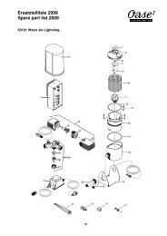
13.1 Freeze damage - Freeze damage can be avoided by keeping the water flowing at all times, withoutinterruption during freezing temperatures. All time clocks must be inoperable <strong>and</strong> the pump must runcontinuously during freezing weather. Freeze damage can also be avoided if the pump <strong>and</strong> EA unit aremaintained inside a warm enclosure.13.2 Freezing Weather Precautions - If you do not plan to operate your EA <strong>UV</strong> unit during freezingtemperatures, you must take precautions to make sure all water is removed from inside the EA wetchamber so it does not freeze inside the wet chamber <strong>and</strong> damage the EA unit. This can be accomplishedby first closing any valves on lines in or out of the EA unit. Next drain the water from the EA unit’s wettank by opening the bottom union so that all water is drained from inside the water chamber tank. A safeprecaution is to place the EA unit in a warm location during freezing temperatures after draining the unit<strong>and</strong> disconnecting it from the plumbing.14.0 Swimming Pool Chemicals – Your EA unit does not add any chemicals to the water it treats. Its job is tokill bacteria, parasites, microorganisms <strong>and</strong> algae that come into contact with the <strong>UV</strong> rays inside the EA unit’swet tank. It is important to maintain a chemical regiment as directed by your pool chemical supplier, however youwill notice a dramatic decrease in chemical usage as one of the side benefits of the EA unit is that it attacks thechloramines that form in pool <strong>and</strong> spa water when sanitizing chemicals are inadequate or when bathing loadsare heavy. Ponds <strong>and</strong> aquatic features obviously do not utilize swimming pool chemicals.15.0 How To Obtain Service – In the unlikelihood that service is required, contact your supplier <strong>and</strong> the suppliercan advise the best method of providing the services you need. In some instances, the supplier will h<strong>and</strong>le therequired service themselves, including the ability to supply any necessary parts. In other instances, the supplierwill refer you to <strong>Delta</strong> <strong>UV</strong>, who can assist you as well. Please read the Limited Warranty in this <strong>manual</strong> for your EA<strong>UV</strong> unit. It explains fully what is <strong>and</strong> what is not covered under the Limited Warranty <strong>and</strong> the warranty periods.16.0 Exploded Parts Diagram - The following diagram shows all replaceable <strong>and</strong> non-replaceable components ofyour EA unit.13
17.0 Frequently Asked Questions - Here are a number of FAQs that will answer some of the most commonquestions.17.1 Is the Elektra® <strong>UV</strong> System Designed For Salt Water Use? - While the ability of the system is notaffected by salt water, the harsh environment found in salt water ponds <strong>and</strong> aquariums is not recommendedfor the EA <strong>UV</strong> units due to the stainless steel construction. Contact your supplier or <strong>Delta</strong> <strong>UV</strong> if you have a saltwater system <strong>and</strong> they will supply you with information on the Elektra ® <strong>UV</strong> system which is totally compatiblewith salt water environments. Salt chlorine generators however are compatible with all <strong>Delta</strong> <strong>UV</strong> systems, asthey operate in a minimum salt level environment. Sea water is not compatible.17.2 Do I Need To Turn My EA Unit Off When I Clean My Filter? - Yes. Anytime the water flow isinterrupted to the EA unit, the power to the unit should be turned off at a switch or breaker controlling thereceptacle that supplies power to the EA unit, BEFORE the water flow is interrupted. If no switch or breakeris convenient, you can accomplish this by simply unplugging the EA unit from it power outlet.17.3 Will A Time Clock On My Pool Shorten My Bulb Life? - Some shortening of the bulb life can beexpected when the EA unit is turned off <strong>and</strong> back on frequently. A daily on/off cycle will not create a majorbulb life issue however, frequent on/off cycles should be avoided.17.4 Is There Any Residual Effect From <strong>UV</strong>? - No, <strong>UV</strong> light is used as a control <strong>and</strong> is applied only tothe water that passes inside the EA wet chamber in visual contact with the <strong>UV</strong> transmission from the <strong>UV</strong>bulb. No chemical change to your pool, spa or pond water takes place.17.5 Can the EA Unit be Mounted Horizontally? - Yes, the EA unit can be installed in any position. Whenmounting the unit, make sure that the water outlet is placed higher than the inlet, so the unit will not drain<strong>and</strong> allow the quartz tube to operated dry. This will ensure that the quartz tube remains submerged at alltimes. When mounting the unit horizontally, either union can be used for inlet or outlet.17.6 Can the EA Unit be Installed Below the Pond, Spa or Pool Waterline? - The EA unit can beinstalled below the waterline. Consideration should be given for future winterizing <strong>and</strong> servicing of the EAunit. The use of valves on both sides of the <strong>UV</strong> unit are a must to isolate the EA from the pool or pond water.NOTE: DO NOT INSTALL ANY EA SERIES UNIT BY IMMERSING IT IN THE VESSEL WATER. All EASeries units are suitable for outdoor <strong>installation</strong>, but are not suitable for immersion in the water. SERIOUSDAMAGE WILL OCCUR TO THE EA UNIT IF SUBMERSED, AS WELL AS RISK OF ELECTRICALSHOCK. Submersion of the unit will void your Limited Warranty.17.7 Can Multiple Units Be Used Together For Larger Systems? - Yes, you can add any numberof EA units to a plumbing bypass manifold system to allow for larger outputs <strong>and</strong> flow rates beyond thecapacity of a single EA-4H-40 unit. <strong>Delta</strong> <strong>UV</strong> also manufactures the Elektra E, Elektra ES, Elektra EP <strong>and</strong>ElektraMax series of <strong>UV</strong> systems for larger capacity ponds <strong>and</strong> pools. If you need to utilize more than twoEA systems to meet your larger pond or pool’s requirements, you will find it more economical to select oneof the other quality <strong>Delta</strong> <strong>UV</strong> systems that are available. Contact your supplier or <strong>Delta</strong> <strong>UV</strong> for completeinformation <strong>and</strong> pricing of these larger capacity <strong>UV</strong> units.17.8 Must I Use a GFCI (Ground Fault Circuit Interrupter) with My <strong>UV</strong> Unit? - Yes, this is a requirementin the US <strong>and</strong> Canada, <strong>and</strong> in some overseas countries. A 15 Amp 120V GFCI needs to be utilized toprotect the EA unit <strong>and</strong> its users. Either a GFCI receptacle (similar to those used in bathrooms) or a GFCIbreaker can be used to provide this important electrical protection.18.0 Troubleshooting – The list below will help guide you through any problems you may have at time of initial<strong>installation</strong> or in the future. For additional assistance, contact your supplier or <strong>Delta</strong> <strong>UV</strong> at the address, e-mail,fax or phone shown at the end of this <strong>manual</strong>.18.1 The <strong>UV</strong> Bulb Will Not Light - If this occurs upon initial start-up, the problem could be caused by anumber of issues.a. The bulb has become disconnected from the bulb connector - Disconnect the power cord14
from the electrical outlet, open the electrical enclosure bonnet <strong>and</strong> confirm the bulb connector isfirmly in place. At the same time, check all exposed wires for a possible loose connection. Plugthe electrical cord back into the electrical outlet ONLY after the electrical enclosure bonnet hasbeen re-installed on the EA unit, <strong>and</strong> the pump is ON.b. Verify that the electrical cord is plugged into a hot outlet - Test the electrical outlet. You shouldconfirm the availability of the same power as indicted on the electrical label on your EA unit.c. Make sure you have not plugged your unit into any power source other than that specifiedon your unit’s electrical label - If you have done so in error, the ballast has been damaged<strong>and</strong> needs to be replaced. Contact your supplier for the correct replacement ballast.18.2 The <strong>UV</strong> Bulb Was Lit But Now Is No Longer Lit - This occurs after the unit has been operatingsuccessfully for a period of time.a. The bulb has burned out. - Replace the <strong>UV</strong> bulb. Contact your supplier or <strong>Delta</strong> <strong>UV</strong> to obtaina replacement bulb for your EA unit.b. The ballast has burned out. - Contact your supplier or <strong>Delta</strong> <strong>UV</strong> for assistance in obtaining anew power cord/ballast assembly.c. There is no power to the outlet - Verify that the electrical outlet where the EA unit is pluggedinto has the proper voltage <strong>and</strong> the EA unit’s power cord is securely plugged into the outlet.d. The GFCI has tripped - Verify that the GFCI has not tripped. To verify the operating state ofthe GFCI, trip the GFCI <strong>manual</strong>ly <strong>and</strong> reset it <strong>manual</strong>ly. The GFCI should reset. If it does not,it indicates a fault to ground in the electrical circuit or the EA unit itself. See Sec. 18.5 for moredetails on GFCI issues.18.3 The <strong>UV</strong> Bulb Stays Lit When The Pump Is Off - The <strong>UV</strong> bulb should not be lit when there is no waterrunning through the EA unit’s wet chamber. This condition will cause the bulb to burn out very quickly due to theheat generated by the <strong>UV</strong> bulb inside the quartz tube when no water is flowing to carry off the heat.a. Time clock interlock missing - If a time clock is used, it should be electrically interlocked tothe electrical outlet servicing the EA unit, so the power to the outlet is interrupted whenever theclock turns the pump OFF. If this condition is present, refrain from using the EA unit until anelectrical interlock is installed.b. EA unit not unplugged when pump is OFF - If no electrical interlock to the pump is present,the electricity to the EA unit must be halted by unplugging the electrical power cord from thewall receptacle before turning OFF the pump. To eliminate this necessity, electrically interlockthe EA unit poser receptacle to the pump.18.4 The Water Is Green - Green water is an indication that the <strong>UV</strong> rays generated by the EA unit are notsufficiently powerful to be effective or are not being generated at all by the <strong>UV</strong> bulb (bulb at end-of-life).a. Bulb not lit - Check the bulb to make sure it is ON. If it is not ON, follow the procedures aboveregarding the <strong>UV</strong> bulb not lighting.b. EA unit not operating long enough - Run your unit longer. If your unit is operating on a timeclock, run the circulation pump longer to allow the EA unit to function fully. It is especially importantto allow the unit to run continuously at initial startup.c. Quartz tube dirty - Clean the quartz tube.d. Bulb at end of life (EOL) - Replace the <strong>UV</strong> bulb if it is nearing the one (1) year useful life. At oneyear of operation, the <strong>UV</strong> bulb is 60% as effective as it was when it was new. This is normal forall low-pressure type <strong>UV</strong> bulbs, which are the longest life bulbs used in this type of application.e. Pool Chemistry Is Off - If your EA unit is installed on a swimming pool, shock the pool withthe sanitizing chemical you normally use <strong>and</strong> balance the pool water as per your chemicalmanufacturers specifications.15
f. Pump Flow Exceeds Unit Design Capacity - Your unit is undersized if the water is not clearingup on a new <strong>installation</strong>. Check the flow rate of the pump <strong>and</strong> compare it to the maximum flowrate for your unit (available online at www.deltauv.com). Flow rates in excess of the maximumflow rate of your <strong>UV</strong> unit will render the system ineffective as there is not sufficient exposuretime of bacterium to the lamp rays. Replace with a properly sized system for your flow rate <strong>and</strong>the water will clear up.18.5 The GFCI Has Tripped - The GFCI protects the system from any fault to ground, as the electricalbreaker protects the electrical circuit. When it trips, it is an indication that there is an electrical problemthat must be corrected to provide a safe operating environment in your pool or pond.a. Test the GFCI - Disconnect the EA unit from the electrical receptacle. Reset the GFCI at thebreaker panel or at the receptacle. If the GFCI does not reset, replace the GFCI. If the GFCIdoes reset, plug the EA unit into the electrical receptacle <strong>and</strong> make sure the pump is on. If theGFCI trips, it is an indication that there is a ground fault inside the EA unit. Follow <strong>instruction</strong>spreviously given for replacing the bulb.b. Inspect the EA unit’s electrical assembly - If water is present inside the electrical enclosureor quartz tube, it will trip the GFCI. Following <strong>instruction</strong>s given previously, remove the quartztube, inspect it for cracks or breakage or for a bad quartz tube seal. Replace the quartz tube ifit is cracked.c. <strong>UV</strong> Bulb is causing GFCI tripping - You can check the <strong>UV</strong> bulb for GFCI trip cause byunplugging the bulb from the bulb connector, then plugging the electrical plug back into theelectrified electrical outlet (make sure the outlet is powered). Reset the GFCI <strong>and</strong> if it does nottrip, it indicates that the <strong>UV</strong> bulb is causing the fault to ground. Replace the <strong>UV</strong> bulb. If the GFCIdoes not reset, then the problem is with the ballast or the electrical power cord. Replace theballast/cord assembly.18.6 The EA Unit Makes Noise When Operating - This is an indication of the EA unit not being properlyattached to a firm mounting base of wood or concrete with the mounting st<strong>and</strong>s <strong>and</strong> b<strong>and</strong> clamps provided. Itcan also indicate that the <strong>UV</strong> bulb was installed without the required bulb cushion <strong>and</strong>/or bulb O-Rings. Attachthe EA unit correctly to a firm base as described in Sec. 5.5, or install the bulb cushion <strong>and</strong>/or bulb O-Rings asdescribed in Sec. 9.1.18.7 Water Is Coming Out Of Electrical Enclosure - Water exiting the unit through the electrical enclosureassembly can be attributed to either (a) a bad quartz tube seal (Factory installed), or (b) a broken or crackedquartz tube. Check the quartz tube for cracks or breakage as instructed in Sec. 7.0 <strong>and</strong> Sec. 8.0. Replace thequartz tube assembly if cracks in the quartz tube are found upon inspection.19.0 Specifications - Due to <strong>Delta</strong> <strong>UV</strong>’s commitment to product improvement, all product descriptions or specificationscontained herein are subject to change without notice.We are confident that your new Elektra® Aquamatic <strong>UV</strong> unit will provide years of service<strong>and</strong> reliable operation with a minimum of maintenance.16
ELEKTRA ® AQUAMATIC LIMITED WARRANTY<strong>Delta</strong> Ultraviolet Corporation warrants to every original Purchaser of <strong>Delta</strong> <strong>UV</strong>’s Elektra ® Aquamatic Series UltravioletUnit, that the product will be free from defects, as defined herein, for a period of either one (1) year. If at any timeduring the Limited Warranty period, any defect, as defined herein, prevents the product from performing correctly inan application for which it was designed, <strong>Delta</strong> <strong>UV</strong> will repair or replace the product (at <strong>Delta</strong> <strong>UV</strong>’s option) as outlinedherein:COVERED WARRANTY ITEMS:This Limited Warranty DOES cover the <strong>UV</strong> unit, its components, <strong>and</strong> defects thereof against:• Manufacturing Defects• Material Defects• Plastic Component Degradation• Bulb failure during 1st year, (Pro Rata)NON-COVERED WARRANTY ITEMS:This Limited Warranty DOES NOT cover the following <strong>UV</strong> unit defects:• Failure Of Any Covered Condition When Caused By Any Of The Following:• Metal Corrosion Due To Salt Water Use• Mechanical Abuse• Glass Component Breakage• Improper Installation• Bulb Failure After 9000 Hours Of Operation• Acts of War or God• Operation At Pressures Greater Than 40 PSI (3 Bar)• Freeze Damage• Any Failure Not Indicated As “Covered Warranty Item” Herein • Improper Operating VoltageNote 1: During the duration of this Limited Warranty, should any failure occur, the unit should be inspected at thesite to determine the cause of failure, <strong>and</strong> if that failure is shown to be a covered item, the Original End User (User)must request a written Return Goods Authorization (RGA) from <strong>Delta</strong> <strong>UV</strong>, prior to any product return. Any returnedunit is to be accompanied by <strong>Delta</strong> <strong>UV</strong>’s RGA <strong>and</strong> is to be returned freight prepaid to <strong>Delta</strong> <strong>UV</strong> for Limited Warrantyevaluation. The User is responsible for any freight damage associated with such return. Unit failures, or componentsthereof, found to be covered under this Limited Warranty will be repaired or replaced (at <strong>Delta</strong> <strong>UV</strong>’s option) withoutcost to the User <strong>and</strong> will be returned to the User via UPS Surface, at the User’s expense. <strong>Delta</strong> <strong>UV</strong> shall be the solejudge in determining the cause of failure of any <strong>UV</strong> unit. Units arriving in broken condition will not be warranted.The term “Original End User” (User) shall mean the person or company that was in possession of the physical locationwhere the <strong>UV</strong> unit was originally installed, at the time of first <strong>installation</strong>, as evidenced by an original invoice from the sellingcompany to the User at the location where the unit is to be returned. A photo copy of said original invoice must accompanythe <strong>UV</strong> unit RGA paperwork. <strong>UV</strong> units received unaccompanied by the required documentation will not be accepted by<strong>Delta</strong> <strong>UV</strong> for Warranty evaluation <strong>and</strong> will be returned to the User in the same condition as received, freight collect (COD) ifthe User fails to provide the required documentation within ten (10) days from date of notification of missing documentationfrom <strong>Delta</strong> <strong>UV</strong>. Any unit returned to <strong>Delta</strong> <strong>UV</strong> COD or freight collect will be rejected from the freight carrier.Note 2: This Warranty is Limited in that it does not cover any monetary reimbursement for freight charges, for removal<strong>and</strong>/or <strong>installation</strong> labor, or any other incurred costs by any other person(s) or firm(s), including (but not limited to) anyconsequential damage or loss of use that might be claimed. The Limited Warranty period shall commence upon thedate of sale to the User, but in all cases no later than one hundred twenty (120) days after the date of manufacture ofthe <strong>UV</strong> unit, as shown on the <strong>Delta</strong> <strong>UV</strong> date code located on the product identification label, whichever occurs first.<strong>UV</strong> units received with factory identification missing, mutilated or altered, or units received containing componentsnot supplied by <strong>Delta</strong> <strong>UV</strong> or modified in any way, will not be warranted under any circumstances.OTHER RIGHTS - This Limited Warranty supersedes any <strong>and</strong> all previous Limited Warranties for this product, givesyou specific legal rights, <strong>and</strong> you may have other rights which vary from state to state.DELTA ULTRAVIOLET CORPORATIONCORPORATE HEADQUARTERS4270 PROMENADE WAY, SUITE DMARINA DEL REY, CA 90292P/N 94-06238 REV. 1/0417
REFERENCE INFORMATIONDEALER ____________________________________________________________________________________________________________________________________________________________________________________________________________PHONE ______________________________________________CONTACT ____________________________________________DATE OF INSTALLATION _________________________________ MODEL _________________RE-LAMP DATE _________________________ RE-LAMP DATE __________________________RE-LAMP DATE _________________________ RE-LAMP DATE __________________________RE-LAMP DATE _________________________ RE-LAMP DATE __________________________RE-LAMP DATE _________________________ RE-LAMP DATE __________________________- NOTES -18
- NOTES -19
4270 Promenade Way, Suite DMarina del Rey, CA 90292310-577-1840 PHONE310-305-9755 FAXCUSTOMERSERVICE@DELTA<strong>UV</strong>.COMIMPORTANT SAFETY INSTRUCTIONSSAVE THESE INSTRUCTIONSP/N 94-35237 Rev. 9/05©2005 <strong>Delta</strong> Ultraviolet Corporation