Jet-X Central Technique.pdf - Bonerepmedical.com
Jet-X Central Technique.pdf - Bonerepmedical.com
Jet-X Central Technique.pdf - Bonerepmedical.com

Create successful ePaper yourself
Turn your PDF publications into a flip-book with our unique Google optimized e-Paper software.
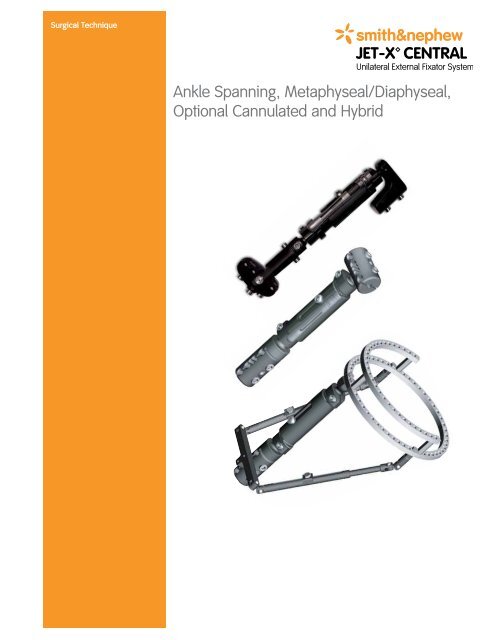
Surgical <strong>Technique</strong><br />
Ankle Spanning, Metaphyseal/Diaphyseal,<br />
Optional Cannulated and Hybrid
JET-X CENTRAL Unilateral External Fixator System<br />
Ankle Spanning, Metaphyseal/Diaphyseal,<br />
Optional Cannulated and Hybrid<br />
Surgical <strong>Technique</strong><br />
Contents<br />
Design Features...........................................................................4<br />
Ankle Spanning Surgical <strong>Technique</strong><br />
Rationale.............................................................................. 14<br />
Surgical <strong>Technique</strong>.............................................................. 15<br />
Metaphyseal/Diaphyseal Surgical <strong>Technique</strong><br />
Rationale............................................................................. 24<br />
Surgical <strong>Technique</strong>............................................................. 25<br />
Hybrid Surgical <strong>Technique</strong><br />
Rationale............................................................................. 30<br />
Surgical <strong>Technique</strong>.............................................................. 31<br />
Important Medical Information.................................................. 34<br />
Catalog Information................................................................... 36<br />
Nota Bene<br />
The technique description herein is made available to the healthcare professional to<br />
illustrate the author’s suggested treatment for the un<strong>com</strong>plicated procedure. In the final<br />
analysis, the preferred treatment is that which addresses the needs of the specific patient.
Design Features<br />
<strong>Central</strong> Body<br />
Part Number:<br />
7105-1041 Short <strong>Central</strong> Body<br />
7105-1042 Standard <strong>Central</strong> Body<br />
7105-1043 Long <strong>Central</strong> Body<br />
7105-1721 Extra Short <strong>Central</strong> Body<br />
Description:<br />
The <strong>Central</strong> Body is the main <strong>com</strong>ponent of the fixator. Complete frames can be easily<br />
constructed by snapping a module onto the ball joint connectors on either end. Each <strong>Central</strong><br />
Body can be <strong>com</strong>pressed or distracted, either acutely or gradually, using the snap-on<br />
Compression/Distraction Device. One Allen Wrench tightens the <strong>Central</strong> Body bolt and each ball<br />
joint bolt.<br />
Engineering Data:<br />
Short <strong>Central</strong> Body<br />
Materials<br />
Overall Distracted Length<br />
Overall Compressed Length<br />
Total Distraction<br />
Wrench Needed<br />
Standard <strong>Central</strong> Body<br />
Materials<br />
Overall Distracted Length<br />
Overall Compressed Length<br />
Total Distraction<br />
Wrench Needed<br />
Long <strong>Central</strong> Body<br />
Materials<br />
Overall Distracted Length<br />
Overall Compressed Length<br />
Total Distraction<br />
Wrench Needed<br />
Extra Short <strong>Central</strong> Body<br />
Materials<br />
Overall Distracted Length<br />
Overall Compressed Length<br />
Total Distraction<br />
Wrench Needed<br />
Carbon Fiber Composite<br />
High Strength Aluminum<br />
Stainless Steel<br />
139mm<br />
119mm<br />
20mm<br />
6mm Allen Wrench<br />
Carbon Fiber Composite<br />
High Strength Aluminum<br />
Stainless Steel<br />
179mm<br />
139mm<br />
40mm<br />
6mm Allen Wrench<br />
Carbon Fiber Composite<br />
High Strength Aluminum<br />
Stainless Steel<br />
249mm<br />
174mm<br />
75mm<br />
6mm Allen Wrench<br />
Carbon Fiber Composite<br />
High Strength Aluminum<br />
Stainless Steel<br />
114mm<br />
104mm<br />
10mm<br />
6mm Allen Wrench<br />
Used with:<br />
Offset Clamp, Straight Clamp, T-Clamp, Ankle Clamp, Ring Adapter, 6mm<br />
Allen Wrench, Compression/Distraction Device<br />
4
Pin Tower<br />
Part Number: 7105-1018<br />
Description:<br />
The Pin Tower allows an additional half pin to be placed oblique to the pin<br />
clamps. It will attach to either the T-Clamp or the Straight Clamp.<br />
Engineering Data:<br />
Materials<br />
Stainless Steel<br />
Overall Height<br />
63.4mm<br />
Overall Width<br />
15.9mm<br />
Wrench Needed<br />
10mm Wrench<br />
6mm Allen Wrench<br />
Used with:<br />
Straight Clamp, T-Clamp, Half Pin, Tissue Protector,<br />
Drill Sleeve, Trocar, 10mm Wrench, 6mm Allen Wrench<br />
Offset Clamp<br />
Part Number: 7105-1722<br />
Description:<br />
The Offset Clamp allows placement of half pins anterior-medial in<br />
the tibia. There are five pin placement options, which hold 5mm or 6mm half<br />
pins. A minimum of two half pins per Offset Clamp is required. Each clamp<br />
is spring -loaded to provisionally grip instruments and pins.<br />
Engineering Data:<br />
Materials:<br />
Total Angulation at the Ball 40°<br />
Distance Between Outer Pins<br />
46mm<br />
Distance From Outer Pins to Center Pin 23mm<br />
Distance From Ball to 5mm Half Pins 39.5mm<br />
Distance From Ball to 6mm Half Pin 40.0mm<br />
Wrench Needed: 6mm Allen Wrench<br />
High Strength Aluminum<br />
Stainless Steel<br />
Used with:<br />
<strong>Central</strong> Body, 5mm or 6mm Half Pin, Tissue Protector, Drill Sleeve, Trocar,<br />
6mm Allen Wrench<br />
5
Translating Ankle Clamp<br />
Part Number: 7105-1054<br />
Description:<br />
The Translating Ankle Clamp is designed to span the ankle for fixation<br />
of pilon fractures. The Ankle Clamp offers two options for calcaneal pin<br />
placement to best fit a patient’s anatomy. It offers independent coronal<br />
and sagittal plane adjustment of the fracture. The removable swivel clamp<br />
is lockable and can be switched from left to right ankle configurations.<br />
The stem’s radiolucent carbon fiber <strong>com</strong>posite material allows clear<br />
visualization of the ankle joint. For stabilization, tightening the center bolt<br />
on the hinge clamp prevents plantar flexion and dorsiflexion.<br />
Engineering Data:<br />
Materials<br />
Carbon Fiber Composite<br />
High Strength Aluminum<br />
Stainless Steel<br />
58.4mm<br />
Distance Between Outer Pins<br />
Total Angulation at the Ball 40°<br />
Diameter of Pin Hole<br />
at Center of Rotation of Hinge 1.6mm<br />
Plantar Flexion 37°<br />
Dorsiflexion 67°<br />
Wrench Needed<br />
6mm Allen Wrench<br />
Used with:<br />
<strong>Central</strong> Body, Half Pin,<br />
Tissue Protector,<br />
Drill Sleeve, Trocar,<br />
6mm Allen Wrench<br />
Straight Clamp<br />
Part Number: 7105-1045<br />
Description:<br />
The Straight Clamp allows placement of half pins in-line with the <strong>Central</strong><br />
Body. There are five pin placement options, and the clamp holds 5mm or<br />
6mm half pins.<br />
A minimum of two half pins per Straight Clamp is required. Each clamp is<br />
spring-loaded to provisionally grip instruments and pins.<br />
Engineering Data:<br />
Materials<br />
Carbon Fiber Composite<br />
High Strength Aluminum<br />
Stainless Steel<br />
Total Angulation at the Ball 40°<br />
Length<br />
102.6mm<br />
Diameter<br />
37mm<br />
Distance from Outer<br />
Pins to Center Pin<br />
23mm<br />
Distance Between Outer Pins 46mm<br />
Wrench Needed<br />
6mm Allen Wrench<br />
Used with:<br />
<strong>Central</strong> Body, Half Pin,<br />
Tissue Protector,<br />
Drill Sleeve, Trocar, 6mm<br />
Allen Wrench<br />
6
T-Clamp<br />
Part Number: 7105-1046<br />
Description:<br />
The T-Clamp allows half pins to be placed transverse to the <strong>Central</strong> Body.<br />
There are five pin placement options, and the clamp will hold 5mm or 6mm<br />
half pins. A minimum of two half pins per T-Clamp is required. Each clamp<br />
is spring-loaded to provisionally grip instruments and pins.<br />
Engineering Data:<br />
Materials<br />
Carbon Fiber Composite<br />
High Strength Aluminum<br />
Stainless Steel<br />
Total Angulation at the Ball 40°<br />
Width<br />
63.2mm<br />
Distance from Outer<br />
Pins to Center Pin<br />
23mm<br />
Distance Between Outer Pins 46mm<br />
Wrench Needed<br />
6mm Allen Wrench<br />
Used with:<br />
<strong>Central</strong> Body, Half Pin, Tissue Protector, Drill Sleeve, Trocar, 6mm<br />
Allen Wrench<br />
Ring Adapter<br />
Part Number: 7105-1047<br />
Description:<br />
The Ring Adaptor connects a JET-X CENTRAL Body to an ILIZAROVT Ring<br />
or TAYLOR SPATIAL FRAME Ring.<br />
Engineering Data:<br />
Materials<br />
Wrench Needed<br />
High Strength Aluminum<br />
Stainless Steel<br />
10mm Wrench (Ring)<br />
6mm Allen Wrench<br />
(<strong>Central</strong> Body)<br />
Used with:<br />
<strong>Central</strong> Body, ILIZAROV Ring, TAYLOR SPATIAL<br />
FRAME Ring, 6mm Wrench, AO T-Handled<br />
Connector w/10mm Socket<br />
7
Hybrid Strut<br />
Part Number:<br />
7105-1048 Short Hybrid Strut<br />
7105-1049 Long Hybrid Strut<br />
Description:<br />
The Hybrid Strut supports the ring on the fixator in a hybrid application.<br />
In a tibial plateau application, the Hybrid Strut attaches distally to the<br />
Straight Clamp and proximally to the ring.<br />
Engineering Data:<br />
Short Hybrid Strut<br />
Materials<br />
Total Telescoping Movement<br />
Wrench Needed<br />
High Strength Aluminum<br />
Stainless Steel<br />
57.2mm<br />
10mm Wrench<br />
6mm Allen Wrench<br />
Long Hybrid Strut<br />
Materials<br />
Total Telescoping Movement<br />
Wrench Needed<br />
High Strength Aluminum<br />
Stainless Steel<br />
108mm<br />
10mm Wrench<br />
6mm Allen Wrench<br />
Used with:<br />
Straight Clamp, ILIZAROVT Ring, TAYLOR SPATIAL FRAME Ring,<br />
10mm Wrench, 6mm Allen Wrench<br />
AO T-Handle Connector with<br />
10mm Socket<br />
Part Number: 7106-3001<br />
Description:<br />
The AO T-Handle Connector with 10mm Socket is a dual-purpose<br />
instrument. The AO Connector allows the manual insertion of half pins<br />
with the T-Handle, while the 10mm Socket provides <strong>com</strong>patibility with<br />
ILIZAROV Composite Rings in hybrid applications.<br />
Engineering Data:<br />
Material<br />
Overall Size<br />
(Top of Handle to End of<br />
Socket)<br />
Handle Size<br />
Connection<br />
Stainless Steel<br />
Used with:<br />
Ring Adaptor, 5mm Half Pin, 10mm Connector<br />
91.4mm<br />
101.6mm x 31.2mm<br />
AO Connection<br />
10mm Socket<br />
8
Compression/Distraction Device<br />
Part Number: 7105-1051 Short <strong>Central</strong> Body<br />
7105-1052 Standard <strong>Central</strong> Body<br />
7105-1053 Long <strong>Central</strong> Body<br />
7105-1721 Extra Short <strong>Central</strong> Body<br />
Description:<br />
The Compression/Distraction Device <strong>com</strong>presses or distracts the <strong>Central</strong><br />
Body. It can be added to the fixator before, during or after surgery. Posts<br />
on both ends of the Device simply plug into the mounting holes on the end<br />
caps of the <strong>Central</strong> Body.<br />
Engineering Data:<br />
Short C/D Device<br />
Materials<br />
Overall Distracted Length<br />
Overall Compressed Length<br />
Total Distraction<br />
Wrench Needed<br />
Stainless Steel<br />
Teflon ®<br />
110mm<br />
90mm<br />
20mm<br />
6mm Allen Wrench<br />
Long C/D Device<br />
Materials<br />
Overall Distracted Length<br />
Overall Compressed Length<br />
Total Distraction<br />
Wrench Needed<br />
Stainless Steel<br />
Teflon<br />
219.5mm<br />
144.5mm<br />
75mm<br />
6mm Allen Wrench<br />
Standard C/D Device<br />
Materials<br />
Overall Distracted Length<br />
Overall Compressed Length<br />
Total Distraction<br />
Wrench Needed<br />
Stainless Steel<br />
Teflon<br />
149.5mm<br />
109.5mm<br />
40mm<br />
6mm Allen Wrench<br />
Extra Short C/D Device<br />
Materials<br />
Overall Distracted Length<br />
Overall Compressed Length<br />
Total Distraction<br />
Wrench Needed<br />
Stainless Steel<br />
Teflon<br />
86mm<br />
76mm<br />
10mm<br />
6mm Allen Wrench<br />
Used with:<br />
<strong>Central</strong> Body, 6mm Allen Wrench<br />
6mm Allen Wrench<br />
Part Number: 7105-3006<br />
Description:<br />
The 6mm Allen Wrench is the only instrument<br />
needed to tighten all JET-X CENTRAL modules.<br />
Engineering Data:<br />
Material<br />
Overall Length<br />
Stainless Steel<br />
190mm<br />
Used with:<br />
<strong>Central</strong> Body, Straight Clamp, T-Clamp, Trauma Ankle Clamp, Pin Tower,<br />
Compression/Distraction Device<br />
9
10mm Ratchet Wrench<br />
Part Number: 7106-3003<br />
Description:<br />
The 10mm Ratchet Wrench may be used with any<br />
10mm connector.<br />
Engineering Data:<br />
Material<br />
Length<br />
Connection<br />
Used with:<br />
Ring Adaptor, Hybrid Strut, Pin Tower<br />
Stainless Steel<br />
159mm<br />
10mm Open-end<br />
10mm Closed-end<br />
3.5mm Graduated Drill<br />
with AO Connector<br />
Part Number: 7106-3006<br />
Description:<br />
The 3.5mm Drill is used to pre-drill for 5mm half pins.<br />
Engineering Data:<br />
Material<br />
Length<br />
Diameter<br />
Connection<br />
Stainless Steel<br />
260.4mm<br />
3.5mm<br />
AO Connection<br />
Used with:<br />
Straight Clamp, T-Clamp, Ankle Clamp, Pin Tower, Tissue Protector, Drill<br />
Sleeve, Half Pin<br />
10
3.5mm/1.6mm Graduated Cannulated Drill<br />
with AO Connector<br />
Part Number: 7106-3013<br />
Description:<br />
The 3.5mm/1.6mm Drill is used to pre-drill over a 1.6mm wire for 5mm<br />
Cannulated Half Pins.<br />
Engineering Data:<br />
Material<br />
Overall Length<br />
Diameter<br />
Cannulation<br />
Connection<br />
Stainless Steel<br />
165.1mm<br />
3.5mm<br />
1.6mm<br />
AO Connection<br />
Used with:<br />
Ankle Clamp, 1.6mm Wire, 1.6mm Wire Guide, Cannulated Pin Tissue<br />
Protector, Cannulated Pin Drill Sleeve, Cannulated Half Pin<br />
Trauma Ankle Clamp Drill Guide<br />
Part Number: 7106-3014<br />
Description:<br />
The Trauma Ankle Clamp Drill Guide assists in pin placement for talar and<br />
calcaneal pins.<br />
Engineering Data:<br />
Materials<br />
Distance Between Outer Pins<br />
Diameter of Pin Hole at Center of<br />
Rotation of Guide<br />
Stainless Steel<br />
Aluminum<br />
Ultem ®<br />
58.4mm<br />
1.6mm<br />
Used with:<br />
1.6mm Wire, 5mm Tissue Protector, Trocar, 3.5mm Drill Sleeve, 5mm Half<br />
Pin, Trauma Ankle Clamp<br />
11
5mm x 40mm x 1.6mm<br />
Cannulated Half Pin<br />
Part Number: 7106-5405<br />
Description:<br />
The 5mm Cannulated Half Pin is used in conjunction with a 1.6mm<br />
Wire for precise placement in the talar neck.<br />
Engineering Data:<br />
Material<br />
Overall Length<br />
Thread Length<br />
Diameter<br />
Cannulation<br />
Connection<br />
Stainless Steel<br />
175mm<br />
40mm<br />
5mm<br />
1.6mm<br />
AO Connection<br />
Used with:<br />
Ankle Clamp, 1.6mm Wire, 1.6mm Wire Guide,<br />
Cannulated Pin Tissue Protector, Cannulated Pin<br />
Drill Sleeve, Cannulated Drill<br />
12
Ankle Spanning Surgical <strong>Technique</strong><br />
13
Rationale<br />
The JET-X CENTRAL Unilateral External Fixator is used<br />
to rapidly stabilize open and/or unstable fractures,<br />
to secure osteotomies and for fracture fixation (open<br />
and closed). It is especially useful in cases where the<br />
soft tissue damage prevents incisions and soft tissue<br />
recovery is needed.<br />
Indications for the JET-X CENTRAL Ankle Fixator<br />
1. The first part of a two-stage treatment protocol<br />
for <strong>com</strong>plex pilon fractures (open reduction and<br />
internal fixation [ORIF] of the fibula and placement of<br />
an external fixation until soft tissue healing occurs to<br />
allow ORIF of the distal tibia).<br />
2. The definitive treatment of ankle and plafond<br />
fractures that cannot be treated by ORIF (ie severely<br />
damaged soft tissue or open fractures).<br />
JET-X CENTRAL Modular Quick Assembly<br />
The modular <strong>com</strong>ponents of the JET-X CENTRAL<br />
Unilateral External Fixation System can be quickly<br />
<strong>com</strong>bined to construct a simple yet versatile ankle<br />
fixation frame. Simply snap-click the Offset Clamp<br />
and Ankle Clamp modules into the connecting ports<br />
at each end of a <strong>Central</strong> Body (short, standard, long<br />
or extra short).<br />
Relevant Anatomy<br />
Care must be taken to avoid neurovascular structures<br />
and intraarticular penetration. Shaded areas: Medial<br />
talar and medial calcaneal safe<br />
pin zones.<br />
14
JET-X CENTRAL Unilateral External Fixator<br />
Ankle Spanning Surgical <strong>Technique</strong><br />
Placement of Ankle Pins<br />
Step One<br />
Make a stab wound in the skin one finger breadth<br />
inferior and one finger breadth anterior to the medial<br />
malleolus parallel to the talus.<br />
Step Two<br />
Bluntly dissect down to the neck of the talus. Place<br />
3.5mm drill guide into 5mm tissue protector, insert<br />
trocar and push to bone to find center of talar neck.<br />
15
Placement of Ankle Pins (Cont.)<br />
Step Three<br />
Insert the 3.5mm graduated drill through the 3.5mm<br />
drill guide and tissue protector, with the C-arm<br />
<strong>com</strong>ing from the ipsilateral side of the injury in the<br />
Mortise view (15° internal rotation from the AP) drill<br />
across the talus parallel to the dome.<br />
Step Four<br />
Verify drill placement on lateral C-arm (A). Remove<br />
3.5mm drill and drill guide. Insert 5mm half pin<br />
through the 5mm tissue protector into the talus<br />
achieving bicortical purchase (B).<br />
A<br />
Option: Manually insert JET-X Half Pins using the<br />
T-handle connector. Attach half pin to the T-handle<br />
connector by pulling back on the gold locking collar.<br />
Note: JET-X Half Pins are self-drilling and selftapping,<br />
and may be inserted under power without<br />
pre-drilling.)<br />
B<br />
16
Placement of Ankle Pins (Cont.)<br />
Step Five<br />
Place the ankle clamp drill guide over the talar half<br />
pin, and then place the 5mm tissue protector over the<br />
talar half pin.<br />
Step Six<br />
Place a 5mm tissue protector and 3.5mm drill guide<br />
in the desired calcaneal slot, and line up the center of<br />
the ankle clamp drill guide at the subtalar joint. Make<br />
a stab wound and bluntly dissect to bone. Place the<br />
5mm tissue protector and 3.5mm drill guide to bone.<br />
Insert self-drilling half pin or pre-drilled half pin.<br />
Remove ankle clamp drill guide.<br />
17
Apply Fixator<br />
Step Seven<br />
Ensure the JET-X CENTRAL Body is extended at least<br />
1cm to allow <strong>com</strong>pression or distraction. Adjust fixator<br />
to appropriate length via telescoping <strong>Central</strong> Body.<br />
Lock <strong>Central</strong> Body telescoping lock using the 6mm<br />
Allen Wrench.<br />
Place the fixator over the talar and calcaneal pins.<br />
Tighten the anterior and posterior bolts on the ankle<br />
clamp with the 6mm Allen Wrench.<br />
Insertion of Proximal Pins<br />
Step Eight<br />
Provisionally tighten the ball joints of the fixator using<br />
the 6mm Allen Wrench for added stability in placing<br />
the tibial half pins.<br />
Use the pin clamp as a template. The spring-loaded<br />
pin clamp will provisionally hold 5mm tissue<br />
protectors in place. Make a stab incision and bluntly<br />
dissect to the anteromedial face of the tibia. Insert<br />
self-drilling or pre-drilled half pins through the<br />
5mm tissue protector. (See Step 3 for pre-drilling<br />
technique.) Remove the tissue protectors and tighten<br />
the pin clamps around the half pins. Leave 2cm<br />
between fixator and skin for swelling. Pins can be<br />
cut at the fixator level and pin caps applied.<br />
Supplementary half pins can be used for additional<br />
stability. (See Pin Tower on Page 20.)<br />
18
Fracture Reduction and<br />
Adjustment<br />
Ball joints allow adjustment in multiple planes.<br />
Step Nine<br />
The JET-X CENTRAL Ankle Fixator is designed to<br />
facilitate obtaining anatomical reduction. Manual<br />
traction and closed manipulation of the fracture to<br />
achieve the best possible reduction prior to placing<br />
half pins is re<strong>com</strong>mended. Adjustments can be<br />
made in multiple planes:<br />
(a) 360° of reduction capability by rotating the ball<br />
joints.<br />
(b) Gross distraction by loosening the locking bolt in<br />
the telescoping <strong>Central</strong> Body.<br />
(c) Flexion/Extension by articulating the Trauma<br />
Ankle Clamp.<br />
(d) Gradual <strong>com</strong>pression/distraction by using the<br />
snap-on Compression/Distraction Device.<br />
40° of total angulation<br />
360° of rotation about the axis of the fixator<br />
Articulating ankle hinge provides up to 38° of plantar<br />
flexion and 67° of dorsiflexion. Once positioned, tighten<br />
the center hinge bolt on the trauma ankle clamp.<br />
<strong>Central</strong> Body telescoping lock allows gross<br />
distraction/<strong>com</strong>pression.<br />
The Compression/Distraction Device can be used<br />
for gradual distraction or <strong>com</strong>pression – either<br />
intra- or post-operatively. Snap the C/D Device<br />
into ports on end caps of <strong>Central</strong> Body. Ensure<br />
the <strong>Central</strong> Body telescoping lock is loosened.<br />
Using the 6mm Allen Wrench, turn clockwise for<br />
<strong>com</strong>pression and counterclockwise for distraction.<br />
Once the desired <strong>com</strong>pression/distraction is<br />
obtained, lock the <strong>Central</strong> Body telescoping bolt.<br />
One revolution corresponds to 1mm of <strong>com</strong>pression<br />
or distraction.<br />
19
Fracture Reduction and<br />
Adjustment (Cont.)<br />
Each ball joint on the JET-X CENTRAL Unilateral<br />
External Fixator provides 360° of rotation about<br />
the axis of the fixator, within 40° of angulation, for<br />
smooth anatomical reduction.<br />
Final Fixator Tightening<br />
Step Ten<br />
After reduction is achieved, ensure the pin clamp<br />
bolts, ball joint bolts, telescoping lock bolt and hinge<br />
bolt are all securely tightened with the 6mm Allen<br />
Wrench. No torque wrench is necessary. Tighten<br />
the ball joint bolt until the gap in the housing is<br />
<strong>com</strong>pletely closed.<br />
Pin Tower<br />
The Pin Tower allows placement of a half pin<br />
convergent to those placed through a Straight or<br />
T-clamp. Attach the Pin Tower to a clamp by<br />
threading the base of the Pin Tower into the threaded<br />
hole located on top of the T-clamp or on the side of<br />
the Straight Clamp. The Pin Tower base should not be<br />
tightened at this point, and the hinge bolt on the Pin<br />
Tower should be loose. Place the<br />
5mm tissue protector through the Pin Tower clamp,<br />
verify location of pin insertion and insert the half pin.<br />
Note: JET-X Half Pins are self-drilling, but could be<br />
pre-drilled if desired.<br />
Tighten the base of the Pin Tower with a 10mm<br />
wrench. Tighten the hinge joint and pin clamp bolts<br />
using the hex wrench.<br />
20
Optional Cannulated <strong>Technique</strong><br />
for Talar Pin Placement<br />
Step One<br />
Make a stab wound in the skin one finger breadth<br />
inferior and one finger breadth anterior to the<br />
medial malleolus parallel to the talus.<br />
Step Two<br />
Bluntly dissect down to the neck of the talus. Use<br />
the 5mm cannulated pin tissue protector; insert the<br />
3.5mm cannulated pin drill sleeve with the inserted<br />
trocar to find the center of the talar neck. Remove<br />
the trocar. Insert the 1.6mm wire guide.<br />
Step Three<br />
With the C-arm <strong>com</strong>ing from the ipsilateral side of<br />
the injury in the Mortise view (15° internal rotation<br />
from the AP view) drill the 1.6mm guide wire across<br />
the talus parallel to the dome.<br />
21
Optional Cannulated <strong>Technique</strong><br />
for Talar Pin Placement (Cont.)<br />
Step Four<br />
Verify guide wire placement on lateral C-arm. Remove<br />
1.6mm wire guide and the 3.5mm cannulated pin<br />
drill sleeve. Drill the 5mm cannulated half pin over<br />
the guide wire into the talus achieving bicortical<br />
purchase.<br />
Option: The talar pin placement may be pre-drilled<br />
using the 3.5/1.6mm graduated cannulated drill.)<br />
Step Five<br />
Place the ankle clamp drill guide over the talar half<br />
pin, and then place the 5mm tissue protector over<br />
the talar half pin. (See Step Six, Ankle Spanning<br />
<strong>Technique</strong> page 17.)<br />
Note: JET-X Half Pins have a tapered minor diameter<br />
and a constant major diameter which maintains<br />
excellent cortical contact even when pin is backed<br />
out to achieve optimal position.<br />
22
Metaphyseal/Diaphyseal Surgical <strong>Technique</strong><br />
23
Rationale<br />
Preoperative planning helps to ensure that the<br />
optimal fixator will be constructed for each case as<br />
dictated by the soft tissue injury and fracture pattern.<br />
It is important to first obtain gross manual alignment<br />
of the fracture.<br />
24
JET-X CENTRAL Unilateral External Fixator<br />
Metaphyseal/Diaphyseal Surgical <strong>Technique</strong><br />
General Half Pin Application<br />
Step One<br />
With any diaphyseal fracture, prior reduction–<br />
especially rotation–is preferred. Place two half pins<br />
on one side of the fracture, preferably the shorter<br />
segment. Use the spring-loaded pin clamps to hold<br />
the 5mm tissue protectors in position.<br />
Step Two<br />
Make a stab skin incision, bluntly dissect to bone,<br />
and place the 5mm tissue protector to bone.<br />
Step Three<br />
Insert the 5mm self-drilling half pins. (Optionally,<br />
pre-drill with a 3.5mm drill.) Once the first pin is<br />
placed, leave the tissue protector guide in place and<br />
insert the second half pin in a similar fashion.<br />
Step Four<br />
Once the second half pin is placed, remove the two<br />
5mm tissue protectors, and tighten the pin clamp.<br />
Assemble the fixator: Snap lock selected pin clamps<br />
into selected <strong>Central</strong> Body ensuring that the <strong>Central</strong><br />
Body of the fixator is lengthened at least 1cm for<br />
<strong>com</strong>pression or distraction.<br />
Step Five<br />
Slightly tightening the ball joint using the 6mm Allen<br />
Wrench gives stability to the frame for placement of<br />
the second set of half pins.<br />
25
General Half Pin Application<br />
(Cont.)<br />
Step Six<br />
Use the second pin clamp as a template for pin<br />
placement. Insert the two half pins through the pin<br />
clamp on the opposite side of the fracture.<br />
Step Seven<br />
Tighten the second pin clamp using the 6mm Allen<br />
Wrench. Make final adjustments using ball joints and<br />
<strong>Central</strong> Body translation. Usually leave 2cm between<br />
the skin and fixator for swelling.<br />
Step Eight<br />
Tighten all bolts using the 6mm Allen Wrench. Ball<br />
joints are sufficiently tightened when the gap in the<br />
housing is <strong>com</strong>pletely closed.<br />
Step Nine<br />
The JET-X CENTRAL Unilateral External Fixator is<br />
designed to facilitate obtaining anatomical reduction.<br />
Manual traction and closed manipulation of the<br />
fracture to achieve the best possible reduction prior<br />
to placing half pins is re<strong>com</strong>mended. Adjustments<br />
can be made in multiple planes:<br />
(a) 360° of reduction capability by rotating the<br />
ball joints.<br />
(b) Gross distraction by loosening the locking bolt in<br />
the telescoping <strong>Central</strong> Body.<br />
(c) Gradual <strong>com</strong>pression/distraction by using the<br />
snap-on Compression/Distraction Device.<br />
(See Page 9 for diagram.)<br />
26
JET-X CENTRAL Unilateral<br />
External Fixator Applications<br />
Tibial Shaft Frame<br />
Fixator is usually placed along the medial face of the<br />
tibia avoiding the muscles of the tibia.<br />
Additional half pins may be used for stability.<br />
Proximal or Distal Tibia Metaphyseal Fracture<br />
Placement of the T-clamp proximal anteromedial.<br />
27
JET-X CENTRAL Unilateral<br />
External Fixator Applications<br />
(Cont.)<br />
Femoral Shaft Fracture<br />
Reduce the fracture, especially rotation. Apply the<br />
clamp laterally. If possible, the half pin should be at<br />
least 3cm from the fracture.<br />
Distal Femur Metaphyseal Fracture<br />
Place the T-clamp fixator distally with the anterior pin<br />
1cm posterior to the anterior cortex and 1cm proximal<br />
to the distal condyle.<br />
Humerus<br />
Unilateral fixator placed laterally. The radial nerve<br />
crosses the potential half pin position, so open<br />
placement at distal half pins is re<strong>com</strong>mended.<br />
28
Hybrid Surgical <strong>Technique</strong><br />
29
Rationale<br />
The JET-X CENTRAL Unilateral External Fixator can<br />
easily ac<strong>com</strong>modate either ILIZAROVT or TAYLOR<br />
SPATIAL FRAME rings using the snap-fit Hybrid Ring<br />
Adaptor.<br />
Indications<br />
Metaphyseal and articular fractures in proximal and<br />
distal tibia and distal femur.<br />
30
JET-X CENTRAL Unilateral External<br />
Fixator Hybrid Surgical <strong>Technique</strong><br />
General <strong>Technique</strong><br />
Step One<br />
Selection of either a full ring (distal tibia) and/or 5/8<br />
ring (distal femur; proximal tibia) is preferred. The<br />
transfixing wire closest to the joint is inserted first,<br />
parallel to the joint surface. Olive wires or smooth<br />
wires can be placed. (Olive wires allow translation<br />
correction along the axis of the wire). The initial<br />
reference wire is tensioned using the dynametric wire<br />
tensioner to the full ring (130 kg) or 5/8 ring<br />
(110 kg).<br />
Proximal Tibia<br />
The proper wire insertion technique is to push the<br />
wire through the soft tissue and drill through the bone<br />
using a moist lap to hold the wire during insertion.<br />
Use the C-arm to ensure the wire is parallel to the<br />
joint. Avoid the joint capsule (in the knee, 14mm<br />
below the joint laterally and 9mm below the joint<br />
medially).<br />
Insert a second transfixing wire on the opposite side<br />
of the ring ensuring the ring remains parallel to the<br />
joint. Additional wires and half pins (using Rancho<br />
cubes) may be added for stability.<br />
Femur Anterior<br />
Distal Tibia<br />
31
Fixator Quick Assembly<br />
Step Two<br />
Select a <strong>Central</strong> Body (short, standard, long or extra<br />
short). Snap Hybrid Ring Adaptor into one end of the<br />
<strong>Central</strong> Body and Straight Clamp into the other end.<br />
Step Three<br />
Using a 10mm wrench, attach the Hybrid Adaptor<br />
to the ring with the 2 bolts. The ball joint in the<br />
Hybrid Adaptor facilitates reduction and optimal pin<br />
placement by providing 20° of adjustment in any<br />
direction. Connect the 5/8 ring to the other ring using<br />
threaded rods and nuts.<br />
Step Four<br />
Select short or long Hybrid Struts. Insert the two<br />
mounting pins located on the hybrid strut-mounting<br />
bar into the central pin slots of the Straight Clamp.<br />
32
Fixator Quick Assembly (Cont.)<br />
Step Five<br />
Attach the arms of the Hybrid Strut to the ring using<br />
10mm bolts and a 10mm wrench. Note that the strut<br />
arm telescopes for length adjustment.<br />
Step Six<br />
Manual traction and closed manipulation of the<br />
fracture to achieve the best possible reduction prior<br />
to placing half pins is re<strong>com</strong>mended. The JET-X<br />
CENTRAL Unilateral External Fixator ball joint and<br />
telescoping <strong>Central</strong> Body provide 360° of rotation<br />
for adjustments. Provisionally tighten ball joints for<br />
stability while placing half pins. Adjustments can be<br />
made in multiple planes:<br />
(a) 360° of reduction capability by rotating the<br />
ball joints.<br />
(b) Gross distraction by loosening the locking bolt in<br />
the telescoping <strong>Central</strong> Body.<br />
(c) Gradual <strong>com</strong>pression/distraction by using the<br />
snap-on Compression/Distraction Device.<br />
(See Page 9 for diagram.)<br />
Step Seven<br />
Use the spring-loaded Straight Clamp as a template<br />
to hold the 5mm tissue protectors in place. Make a<br />
stab incision, bluntly dissect to bone and place tissue<br />
protector to bone.<br />
Step Eight<br />
Insert the 5mm half pins. (JET-X Half Pins are selfdrilling,<br />
self-tapping and may be inserted under<br />
power. Each pin end is AO quick connect for faster<br />
technique.) (Option: pre-drill with 3.5mm drill.)<br />
Step Nine<br />
Tighten the pin clamp using the 6mm Allen Wrench.<br />
Make final adjustments using ball joints and <strong>Central</strong><br />
Body. The snap-on Compression/Distraction Device<br />
may be used intra- or post-operatively.<br />
Step Ten<br />
Leave 2cm between fixator and skin to allow for<br />
swelling. Tighten all bolts using the 6mm Allen<br />
Wrench and 10mm Ratchet Wrench.<br />
33
Important Medical Information<br />
External Fixation Systems<br />
SPECIAL NOTE<br />
External fixation should be used only under the directions of physicians who have a thorough<br />
knowledge of the anatomy, physiology and surgical principles involved. Physicians are strongly<br />
encouraged to obtain instruction from experienced clinicians or to observe surgical application of<br />
the apparatus prior to its initial use.<br />
DESCRIPTION<br />
External Fixation Systems consist of various <strong>com</strong>ponents used to build constructs to treat<br />
the indications listed below. External Fixation Systems are modular, therefore, different frame<br />
configurations are possible. An individualized configuration should be designed for each case<br />
to suit the specific application. Refer to supporting instruction information provided by Smith<br />
& Nephew or <strong>com</strong>ponent information assembly instructions, and surgical techniques for each<br />
individual external fixation system. All External Fixation System <strong>com</strong>ponents are designed for<br />
single use only.<br />
Unless outlined in supporting instructional information, each External Fixation System is<br />
designed as a system and does not allow the substitution of <strong>com</strong>ponents from other systems or<br />
manufacturers.<br />
External Fixation Systems are made from various types of metal, plastic, and <strong>com</strong>posite materials.<br />
The <strong>com</strong>ponent material is provided on the outside carton label.<br />
The COMPASS Universal Hinge is used with the ILIZAROV TM External Fixator to control distraction<br />
and rotation of an injured joint to regain, maintain, or increase the range of motion of the joint. It<br />
utilizes circular frame and half-pin fixation techniques and procedures for placement of the device.<br />
The device is intended to be centered on the axis of rotation. The device allows some adjustability<br />
to permit adjustment on the axis. Please refer to the surgical technique for <strong>com</strong>plete details of the<br />
re<strong>com</strong>mended procedures.<br />
The TAYLOR SPATIAL FRAME Fixator utilizes <strong>com</strong>puter software to re<strong>com</strong>mend adjustments to the<br />
fixation frame based on surgeon-derived measurements and examination.<br />
INDICATIONS<br />
1. Post-Traumatic joint contracture which has resulted in loss of range of motion (not applicable for<br />
Smith & Nephew Rail System)<br />
2. Fractures and disease which generally may result in joint contractures or loss of range of motion<br />
and fractures requiring distraction<br />
3. Open and closed fracture fixation<br />
4. Pseudoarthrosis of long bones<br />
5. Limb lengthening by epiphyseal or metaphyseal distraction (not applicable for COMPASS<br />
Universal Hinge or JET-X Fixator)<br />
6. Correction of bony or soft tissue deformities (not applicable for COMPASS Universal Hinge)<br />
7. Correction of segmental bony or soft tissue defects<br />
8. Joint arthrodesis (not applicable for Smith & Nephew Rail System)<br />
9. Infected fractures or nonunions<br />
10. Mini external fixator systems are indicated for the management of <strong>com</strong>minuted intra-articular<br />
fractures of the distal radius (not applicable for Smith & Nephew Rail System)<br />
11. Calandruccio devices are indicated for arthrodesis of the ankle or subtalar joints, as well as<br />
some select fractures, nonunion, or osteotomy of the distal tibia; and acute transverse fractures<br />
or nonunion of the distal tibia (not applicable for Smith & Nephew Rail System)<br />
CONTRAINDICATIONS<br />
External fixation devices are contraindicated for use in uncooperative or mentally in<strong>com</strong>petent<br />
patients who are unable to follow the postoperative regimen.<br />
Calandruccio devices are also contraindicated for fractures that will most likely heal satisfactorily<br />
with noninvasive conservative management, either casting or cast bracing without loss of joint<br />
function. Other contraindications include fractures or nonunions which do not permit multiple pin<br />
fixation in the coronal plane and patients with medical problems that require weight-bearing on<br />
the extremity.<br />
WARNINGS<br />
1. The correct selection of device <strong>com</strong>ponents is extremely important. The appropriate type and<br />
size should be selected for the patient based on injury, weight, <strong>com</strong>pliance, etc.<br />
2. Preliminary frame assembly is re<strong>com</strong>mended to reduce operative times and to assure an<br />
adequate supply of <strong>com</strong>ponents prior to surgery.<br />
3. Intraoperative fracture or instrument breakage can occur. Instruments which have been used<br />
extensively or with excessive force are susceptible to fracture. Examine all instruments for wear<br />
and damage prior to surgery. Replace where necessary. Single use devices should not be<br />
reused due to risks of breakage, failure or patient infection.<br />
4. Correction of varus, valgus, procurvatum, and recurvatum movement of limb segments during<br />
distraction should be planned preoperatively by selecting an appropriate prophylactic ring tilt<br />
and strategically positioning wires with stoppers, fulcrums, half pins, and hinges.<br />
5. Wire and pin placement requires strict anatomical consideration to avoid damage to nerves,<br />
muscles, tendons, and vessels. Wires should be gently pushed through soft tissue, not drilled,<br />
to reduce the possibility of injury.<br />
6. Wire drilling through the bone should be done slowly to avoid heat necrosis of surrounding<br />
tissues and bone.<br />
7. Use caution when handling the sharp tips of wires. The tip of the wire should be held when<br />
clipped. Eye protection is re<strong>com</strong>mended for operating room personnel.<br />
8. Pin/wire site care is crucial in reducing infections.<br />
9. Periodic postoperative follow-up and radiographs are re<strong>com</strong>mended during the distraction phase.<br />
PRECAUTIONS<br />
1. Use extreme care in handling and storing <strong>com</strong>ponents. Cutting, bending, or scratching the<br />
surface of <strong>com</strong>ponents can reduce the strength and fatigue life of the device. Any <strong>com</strong>ponents<br />
damaged during the course of the treatment should be replaced. Wire bending can be avoided<br />
by using various types of washers to build the ring to the wire.<br />
2. Surgical technique information is available upon request. The surgeon should be familiar with<br />
the devices, instruments and surgical technique prior to surgery.<br />
3. Unless specified, only <strong>com</strong>ponents from the same system should be used together. Refer to<br />
supporting instruction information for details on each external system.<br />
4. Proper fixation and assembly of <strong>com</strong>ponents are essential. All wires and miscellaneous parts<br />
should be securely fastened with the appropriate instrument. Wires should be tensioned as<br />
specified in product literature.<br />
5. The proper wire diameter should be used to ensure sufficient wire strength and to maintain<br />
appropriate axial stiffness of the apparatus. The 1.8 mm wires are usually re<strong>com</strong>mended for the<br />
tibia and femur in normal adults, while the 1.5 mm wires are usually re<strong>com</strong>mended for the upper<br />
limbs and pediatric lower limb applications.<br />
6. The diameter of the rings, assembled half rings or frames, are re<strong>com</strong>mended to be about 4cm<br />
larger than the maximum diameter of the operated limb segment to ac<strong>com</strong>modate swelling.<br />
7. Wire/pin security in bone, wire tension, and device frame integrity should be routinely checked.<br />
The gap at a fracture site should be reassessed during healing. Adjustments should be made<br />
as necessary.<br />
8. The patient should be instructed to report any adverse or unanticipated effects to the physician<br />
as soon as possible and should also be advised of the distraction and adjustment requirement.<br />
9. Preoperative planning for the TAYLOR SPATIAL FRAME Fixator requires special software and<br />
programs. Accurate inputs are critical for accurate results. Verify and double check all input<br />
parameters. The <strong>com</strong>puter program should be run twice to verify that the parameters have<br />
been correctly entered into the software. The TAYLOR SPATIAL FRAME Fixator can be used as a<br />
template to <strong>com</strong>pare the adjusted frame to the deformity to verify fit. Output of strut lengths from<br />
the program can exceed any strut length for a particular preassembled frame. If this occurs,<br />
refer to Surgical <strong>Technique</strong> and Instruction Manuals.<br />
10. Intraoperative placement of the TAYLOR SPATIAL FRAME Fixator according to preoperative plans<br />
is imperative to achieve predetermined results. If intraoperative conditions require a change to<br />
frame placement (eccentricity) or size (parameters), new strut lengths should be calculated by<br />
entering the new inputs into the program. Small changes may affect accuracy of out<strong>com</strong>e.<br />
11. Touch down weight bearing may be allowed postoperatively. Weight bearing may be increased<br />
as the callus thickens.<br />
12. For patients with Calandruccio devices, postoperative care and physical therapy should be<br />
structured to prevent weight bearing on the operated leg until sufficient healing is evident on<br />
the x-ray.<br />
13. MRI Information<br />
JET-X Unilateral External Fixator System <strong>com</strong>ponents are labeled MR Conditional according to<br />
the terminology specified in ASTM F2503-05, Standard Practice for Marking Medical Devices and<br />
Other Items for Safety in the Magnetic Resonance Environment.<br />
Non-clinical testing demonstrated that the JET-X Unilateral External Fixator System <strong>com</strong>ponents,<br />
when used in the specific configuration stated herein, are MR Conditional. Representative JET-X<br />
Unilateral External Fixator System <strong>com</strong>ponents used in a typical construct included bar/pin clamps,<br />
multi-pin clamps, <strong>com</strong>posite bars and metal half pins. A patient with the JET-X Unilateral External<br />
Fixator System can be scanned safely immediately after placement under the following conditions:<br />
• Static magnetic field of 1.5-Tesla with the center of the JET-X Unilateral External Fixator System<br />
frame positioned at least 30cm from the isocenter of the bore<br />
• Static magnetic field of 3.0-Tesla with no restriction for the position of the JET-X Unilateral<br />
External Fixator System frame<br />
• Highest spatial gradient magnetic field of 720-Gauss/cm or less<br />
• Maximum MR system reported, whole-body-averaged specific absorption rate (SAR) of 2 W/kg,<br />
(i.e. normal operating mode only).<br />
Note: In non-clinical testing, a JET-X Unilateral External Fixator System construct (<strong>com</strong>prised of 4<br />
bar/pin clamps, 4 stainless steel half pins and a 350mm long <strong>com</strong>posite bar) was <strong>com</strong>bined with<br />
a JET-X Unilateral External Fixator System Knee Spanning fixator construct (<strong>com</strong>prised of 4 bar/pin<br />
clamps, 3 bar/bar clamps, 1 multiple pin clamp, 4 stainless steel half pins and 3 <strong>com</strong>posite bars<br />
ranging from 150mm to 600mm in length) to produce the worst-case “conduction loop”. In this<br />
non-clinical testing, the maximum observed heating was 19°C for 1.5T and 5.7°C for 3.0T. Because<br />
higher in vivo heating could be possible, close patient monitoring and <strong>com</strong>munication with the<br />
patient during scanning is required.<br />
Patients may be safely scanned in the MRI chamber when the center of the JET-X Unilateral<br />
External Fixator System frame is positioned at least 30cm from the isocenter/longitudinal center of<br />
the bore of the magnet. To maintain this distance, patients may need to be positioned differently<br />
dependent on the anatomic placement of the JET-X Bar fixator frame (e.g. on the Upper or<br />
Lower extremity). All other Smith & Nephew External Fixation Systems do not claim MRI safety<br />
or conditionality and no testing has been performed to evaluate the products for safety and<br />
<strong>com</strong>patibility in the MR environment. The External Fixation Systems have not been tested for<br />
heating or migration in the MR environment.<br />
Artifact Information<br />
MR image quality may be <strong>com</strong>promised if the area of interest is in the exact same area or relatively<br />
close to the position of the JET-X Unilateral External Fixator System construct. Therefore, it may be<br />
34
necessary to optimize MR imaging parameters in order to <strong>com</strong>pensate for the presence of the JET-X<br />
Unilateral External Fixator System construct.<br />
Representative <strong>com</strong>ponents used to assemble a typical JET-X Unilateral External Fixator System<br />
construct have been evaluated in the MRI chamber. Artifact test results are summarized below.<br />
Overall, artifacts created by JET-X Unilateral External Fixator System <strong>com</strong>ponents may present<br />
problems if the MR imaging area of interest is in or near the area where the JET-X Unilateral External<br />
Fixator System construct is located. See Table 1 below for artifact information.<br />
Table 1 - Summary of MRI Artifacts @ 3-Tesla for Components of the JET-X Unilateral External Fixator<br />
System<br />
Artifact Information<br />
JET-X CENTRAL-to-Pin Clamp (51mm x 32mm x 25mm)<br />
Pulse Sequence T1 - SE T1 - SEGREGRE<br />
Signal Void Size13,652 mm 2 11,555 mm 2 21,494 mm 2 21,809 mm 2<br />
Imaging Plane Parallel (long axis) Perpendicular<br />
(short axis)<br />
Parallel (long axis)<br />
JET-X 350mm Composite Bar (10.5mm diameter x 350mm long)<br />
Pulse Sequence T1 - SE T1 - SEGREGRE<br />
Signal Void Size1,726 mm 2 109 mm 2 1,823 mm 2 112 mm 2<br />
Imaging Plane Parallel (long axis) Perpendicular<br />
(short axis)<br />
Parallel (long axis)<br />
JET-X Long Titanium Nitride Half Pin (6mm diameter x 232mm long)<br />
Pulse Sequence T1 - SE T1 - SE GRE GRE<br />
Perpendicular (short<br />
axis)<br />
Perpendicular (short<br />
axis)<br />
Signal Void Size 6,311 mm 2 2,446 mm 2 12,073 mm 2 6,115 mm 2<br />
Imaging Plane Parallel (long axis)Perpendicular<br />
(short axis)<br />
Parallel (long axis)Perpendicular (short<br />
axis)<br />
JET-X Multi-Pin Clamp (102mm x 32mm x 25mm)<br />
Pulse Sequence T1 - SE T1 - SE GRE GRE<br />
Signal Void Size26,643 mm 2 12,200 mm 2 25,538 mm 2 23,800 mm 2<br />
Imaging Plane Parallel (long axis) Perpendicular<br />
(short axis)<br />
T1 - SE = T1-weighted spin echo<br />
GRE = gradient echo<br />
Parallel (long axis)<br />
Perpendicular (short<br />
axis)<br />
ADVERSE EFFECTS<br />
1. Damage to nerves or vessels resulting from insertion of wires and pins<br />
2. Infection including persistent drainage of the pin tracts, or after wire removal; chronic pin/wire site<br />
osteomyelitis<br />
3. Edema or swelling, possible <strong>com</strong>partment syndrome<br />
4. Joint contracture, loss of range of motion or reduction, joint subluxation or dislocation<br />
5. Septic arthritis and osteomyelitis<br />
6. Loosening or breakage of the pins, wires, or other <strong>com</strong>ponents including inadvertent injury to<br />
the patient or operating room personnel caused by the wire (e.g. projective wire from tip cutting<br />
during surgery)<br />
7. Intractable pain or delayed unions or both<br />
8. Persistence or reoccurrence of the initial condition requiring treatment<br />
9. Reoperation to replace a <strong>com</strong>ponent or the entire apparatus<br />
10. Foreign body reaction to pins, wires, or other <strong>com</strong>ponents<br />
11. Tissue necrosis occurring during pin or wire insertion or at the pin/wire tissue junction<br />
12. Excessive operative bleeding or muscle tendon impalement<br />
13. Skin pressure problems caused by external <strong>com</strong>ponents<br />
14. The intrinsic risks associated with anesthesia<br />
15. Premature consolidation during bone elongation<br />
16. Secondary equinus contracture<br />
17. Failure of bone to regenerate satisfactorily; development or persistence of nonunion or<br />
pseudoarthrosis<br />
18. Fracture of regenerated bone or fracture through a hole after removal of the device<br />
19. Abnormal growth plate development in patients who are not skeletally mature, including<br />
premature fusion, and slowed or accelerated growth<br />
20. Loss of bone mass due to “stress shielding”<br />
21. Limb length discrepancy<br />
22. Bone sequestration secondary to rapid drilling of the bony cortex, with heat build-up and bone<br />
necrosis<br />
23. Excessive motion at the fracture site due to failure to tighten the <strong>com</strong>ponent parts of the device;<br />
improper tensioning of wires, flexion from use of too few pins or pins that are too small<br />
24. Ankle stiffness if multiple transfixion pins are used in tibial fractures<br />
25. Thrombosis, late erosion or arteriovenous fistulas<br />
26. Persistent drainage after wire removal; chronic wire site osteomyelitis<br />
27. Bone deformity<br />
28. Inability to <strong>com</strong>press the bone surface if the pins are not securely seated in bone<br />
PACKAGING AND LABELING<br />
Components should only accepted if received by the hospital or surgeon with the factory<br />
packaging and labeling intact. For implants that are provided sterile, if the sterile barrier has<br />
been broken, return the <strong>com</strong>ponent to Smith & Nephew, Inc.<br />
STERILIZATION<br />
For <strong>com</strong>ponents provided sterile, the sterilization method is noted on the label. Sterile<br />
implant <strong>com</strong>ponents are supplied sterile to a Sterility Assurance Level (SAL) of 10 -6 . Sterile<br />
packaged implant <strong>com</strong>ponents are supplied in protective sterile barrier packaging. Inspect<br />
packages for punctures or other damage prior to surgery. If the sterile barrier has been<br />
broken, return the <strong>com</strong>ponent to Smith & Nephew, Inc.<br />
If not specifically labeled sterile, the <strong>com</strong>ponents are supplied non-sterile and must<br />
be cleaned and sterilized prior to surgery. For non-sterile external fixation devices,<br />
remove all original packaging and labeling inserts prior to sterilization.It is important that<br />
adequate cleaning be carried out prior to sterilization. Please also see the document,<br />
“Re<strong>com</strong>mendations for decontamination and sterilization of Smith & Nephew orthopaedic<br />
devices,” which is provided with Smith & Nephew instrument sets, for further information on<br />
cleaning instructions and validated sterilization procedures.<br />
DO NOT REUSE implant <strong>com</strong>ponents or single use disposable instruments.<br />
HA coated half pins are provided STERILE packaged and cannot be resterilized.<br />
RECOMMENDED STEAM STERILIZATION CYCLE PARAMETERS (for devices provided nonsterile)<br />
• Dynamic Air Removal (Prevacuum) Steam Cycle: 132°C (270°F) for 4 minutes or 135°C<br />
(275°F) for 3 minutes, and a minimum vacuum drying time of 30 minutes.<br />
• Flash Steam Cycle (Reusable instruments only): 132°C (270°F) for 10 minutes in a Gravity<br />
Displacement Cycle or 4 minutes in a Dynamic Air Removal (Prevacuum) Cycle.<br />
• United Kingdom Steam Cycle: 134°C (273°F) for 3 minutes and a minimum vacuum drying<br />
time of 30 minutes. (Note: Sterilization evacuation and pulsing should be carried out in<br />
accordance to HTM 2010).<br />
Containment devices should be wrapped with an approved central supply wrap (CSR) or<br />
placed in an approved reusable rigid container for sterilization. All sterilization wraps may not<br />
be approved for all cycle types. Check with manufacturer for approvals.<br />
RETRIEVAL AND ANALYSIS OF REMOVED IMPLANTS<br />
The most important part of surgical implant retrieval is preventing damage that would render<br />
scientific examination useless. Special care should be given to protect the implant from<br />
damage during handling and shipment. Follow internal hospital procedures for the retrieval<br />
and analysis of implants removed during surgery. When handling removed implants, use<br />
precautions to prevent spread of bloodborne pathogens.<br />
If the implant will be returned to Smith & Nephew, Inc. for analysis, contact Customer Service<br />
using the phone numbers outlined in the Information section.<br />
INFORMATION<br />
For further information, please contact Customer Service at (800) 238-7538 for calls within<br />
the continental USA and (901) 396-2121 for all international calls.<br />
Caution: Federal Law (USA) restricts this device to sale by or on the order of a<br />
physician.<br />
Trademark of Smith & Nephew, Certain Marks Reg. in US Pat. & TM Off., All trademarks<br />
acknowledged.<br />
Manufacturing facilities and EC representative:<br />
Smith & Nephew Inc.<br />
1450 Brooks Road<br />
Memphis, TN 38116 USA<br />
Tel.: 901-396-2121<br />
Smith & Nephew Orthopaedics GmbH<br />
Alemannenstrasse 14<br />
78532 Tuttlingen, Germany<br />
Tel.: 07462/208-0<br />
Fax: 07462/208-135<br />
81056329 Rev. C 2010-04<br />
35
Catalog Information<br />
JET-X CENTRAL – Implants<br />
Large Fixed Straight Clamp<br />
Cat. No. 7105-1005<br />
Male Ring Adaptor<br />
(Not shown)<br />
Cat. No. 7105-1016<br />
<strong>Central</strong> Body – Carbon Composite, High Strength<br />
Aluminum, Stainless Steel<br />
Description<br />
Overall<br />
Compressed<br />
Length<br />
Overall<br />
Distracted<br />
Length<br />
7105-1041 Short 119mm 139mm<br />
7105-1042 Standard 139mm 179mm<br />
7105-1043 Long 174mm 249mm<br />
7105-1721 Extra Short 104mm 114mm<br />
Straight Clamp<br />
Cat. No. 7105-1045<br />
T-Clamp<br />
Cat. No. 7105-1046<br />
Ring Adaptor<br />
Cat. No. 7105-1047<br />
Short Hybrid Support Struts<br />
Cat. No. 7105-1048<br />
36
JET-X CENTRAL – Implants<br />
Long Hybrid Support Struts<br />
Cat. No. 7105-1049<br />
<strong>Central</strong> Modules<br />
Description<br />
7105-1051 Short<br />
7105-1052 Standard<br />
7105-1053 Long<br />
Description<br />
7105-1720 Extra Short C/D<br />
Translating Ankle Clamp<br />
Cat. No. 7105-1054<br />
Straight Connector<br />
Cat. No. 7105-1055<br />
Hinged Connector<br />
Cat. No. 7105-1056<br />
Offset Clamp<br />
Cat. No. 7105-1722<br />
Hybrid Clamp<br />
(Not shown)<br />
Cat. No. 7105-1723<br />
37
JET-X CENTRAL – Instruments<br />
10.5mm to Ring Freedom Clamp<br />
Cat. No. 7106-2722<br />
Pin Tower<br />
Cat. No. 7105-1018<br />
1.6mm x 240mm Wire<br />
Cat. No. 7105-1039<br />
6mm Allen Wrench<br />
Cat. No. 7105-3006<br />
AO T-handle Connector<br />
with 10mm Socket<br />
Cat. No. 7106-3001<br />
10mm Ratchet Wrench<br />
Cat. No. 7106-3003<br />
3.5mm Drill with AO Connector<br />
Cat. No. 7106-3006<br />
5mm Tissue Protector<br />
Cat. No. 7106-3007<br />
3.5mm Drill Sleeve<br />
Cat. No. 7106-3008<br />
38
JET-X CENTRAL – Instruments<br />
1.6mm Wire Guide<br />
Cat. No. 7106-3011<br />
5mm Trocar<br />
Cat. No. 7106-3012<br />
1.6mm/3.5mm Cannulated Drill<br />
with AO Connector<br />
Cat. No. 7106-3013<br />
Ankle Clamp Drill Guide<br />
Cat. No. 7106-3014<br />
10mm Open-faced Ratchet Wrench<br />
Cat. No. 7106-3015<br />
5mm Cannulated Pin Tissue Protector<br />
Cat. No. 7106-3017<br />
3.5mm Cannulated Pin Drill Sleeve<br />
Cat. No. 7106-3018<br />
Translating Ankle Clamp Drill Guide<br />
(Not shown)<br />
Cat. No. 7106-3019<br />
39
JET-X CENTRAL – Instruments<br />
Combination Tissue Protector & Drill<br />
Sleeve for 6mm Half Pins<br />
Cat. No. 7106-3022<br />
Extra Short Tissue Protector<br />
Cat. No. 7106-3023<br />
4.8mm Step Drill for 6mm Half Pins<br />
Cat. No. 7106-3025<br />
4.8mm Graduated Step Drill for 6mm<br />
Short Half Pins<br />
Cat. No. 7106-3026<br />
Drill Sleeve with Trocar for 5mm/6mm<br />
Short Half Pins<br />
Cat. No. 7106-3027<br />
5mm/6mm Tissue Protector For Short<br />
Half Pin<br />
Cat. No. 7106-7313<br />
AO T-handle Connector with<br />
10mm Socket<br />
Cat. No. 7106-7326<br />
40
JET-X CENTRAL – Instruments<br />
Instrument Case<br />
Cat. No. 7105-3050<br />
Instrument Set<br />
Set No. 7105-9000<br />
Description<br />
Qty<br />
7105-3006 6mm Allen Wrench 1<br />
7105-3050 Instrument Case 1<br />
7106-3001 AO T-handle Connector with 10mm 1<br />
7106-3003 10mm Ratchet 1<br />
7106-3006 3.5mm Drill with AO Quick Connect 2<br />
7106-3007 5mm Tissue Protector 4<br />
7106-3008 3.5mm Drill Sleeve 2<br />
Description<br />
Qty<br />
7106-3011 1.6mm Wire Guide 2<br />
7106-3012 5mm Trocar 1<br />
7106-3013 3.5mm/1.6mm Cannulated Drill 1<br />
7106-3014 Ankle Clamp Drill Guide 1<br />
7106-3017 5mm Cannulated Pin Tissue Protector 2<br />
7106-3018 3.5mm Cannulated Pin Drill Sleeve 2<br />
Implant Set<br />
Set No. 7105-9002<br />
Description<br />
Qty<br />
7105-1018 Pin Tower 1<br />
7105-1039 1.6mm x 240mm Wire 4<br />
7105-1041 Short Body 1<br />
7105-1042 Standard Body 1<br />
7105-1045 Straight Clamp 2<br />
7105-1046 T-Clamp 1<br />
7105-1051 Short C/D Module 1<br />
7105-1052 Standard C/D Module 1<br />
7105-1054 Translating Trauma Ankle 1<br />
7105-1722 Offset Clamp 2<br />
7105-1723 Hybrid Clamp 1<br />
Description<br />
7105-3751 Implant Case 1<br />
7106-5301 5mm x 30mm Short Half Pin 6<br />
7106-5308 TiN 5mm x 30mm Short Half Pin 6<br />
7106-5401 5mm x 40mm Short Half Pin 6<br />
7106-5405 5mm x 40mm x 175mm 1.6 Cannulated 6<br />
Half Pin<br />
7106-5407 TiN 5mm x 40mm 1.6 Cannulated 6<br />
Half Pin<br />
7106-5408 TiN 5mm x 40mm Short Half Pin 6<br />
7106-5701 5mm x 70mm Short Half Pin 6<br />
7106-5708 TiN 5mm x 70mm Short Half Pin 6<br />
Qty<br />
41
JET-X CENTRAL Hybrid – Implants<br />
Slotted Wire Fixation Bolt<br />
Cat. No. 100700<br />
Olive Wire, 400mm<br />
Cat. No. 102107<br />
20mm Connection Bolt<br />
Stainless Steel, Box Quantity 20<br />
Cat. No. 103203<br />
10mm Nut<br />
Stainless Steel, Box Quantity 20<br />
Cat. No. 103300<br />
5mm Centering Sleeve<br />
Cat. No. 103405<br />
1 Hole Rancho Cube<br />
Cat. No. 103451<br />
3 Hole Rancho Cube<br />
Cat. No. 103453<br />
Ring Adaptor<br />
Cat. No. 7105-1047<br />
Short Hybrid Support Strut<br />
Cat. No. 7105-1048<br />
42
JET-X CENTRAL Hybrid – Implants<br />
Long Hybrid Support Strut<br />
Cat. No. 7105-1049<br />
8mm Body Bolt<br />
Cat. No. 7105-3030<br />
Pin Clamp Locking Bolt, 8mm Cap<br />
Cat. No. 7105-3031<br />
8mm Pin Clamp Spring<br />
Cat. No. 7105-3032<br />
8mm <strong>Central</strong> Body Lock Bolt Washer<br />
Cat. No. 7105-3033<br />
8mm Ball Joint Locking Bolt<br />
Cat. No. 7105-3038<br />
Dynamometric Wire Tensioner<br />
Cat. No. 7107-0341<br />
43
JET-X CENTRAL Hybrid – Sets<br />
Hybrid Case<br />
Cat. No. 7105-3060<br />
Hybrid Set<br />
Set No. 7105-9004<br />
Description<br />
Qty<br />
100700 Wire Fixation Bolt, Slotted 5<br />
102107 Wire with Stopper, 400mm 12<br />
103203 Bolt, 20mm 20<br />
103300 Nut, 10mm 20<br />
103405 Centering Sleeve, 5mm 6<br />
103451 Rancho Cube, 1 Hole 4<br />
103453 Rancho Cube, 3 Hole 4<br />
Description<br />
Qty<br />
7105-1047 Ring Adaptor 1<br />
7105-1048 Short Hybrid Strut 1<br />
7105-1049 Long Hybrid Strut 1<br />
7107-0341 Dynametric Wire Tensioner 1<br />
7112-9401 Small Outer Case, 2.4 inches 1<br />
7112-9402 Lid for Outer Case 1<br />
44
JET-X CENTRAL Hybrid – Sets<br />
Implant Case<br />
Cat. No. 7105-3751<br />
Implant/Instrument Set<br />
Set No. 7105-9005<br />
Description<br />
7105-1018 Pin Tower 1<br />
7105-1039 1.6mm x 240mm Wire 4<br />
7105-1041 Short Body 1<br />
7105-1042 Standard Body 1<br />
7105-1043 Long Body 1<br />
7105-1045 Straight Clamp 2<br />
7105-1046 T Clamp 1<br />
7105-1051 C/D Module, Short 1<br />
7105-1052 C/D Module, Standard 1<br />
7105-1053 C/D Module, Long 1<br />
7105-1054 Translating Trauma Ankle Clamp 1<br />
7105-3006 6mm Allen Wrench 2<br />
7105-3050 Instrument Case 1<br />
7105-3751 Implant Case 1<br />
7106-3001 AO T-handle Connector with 1<br />
10mm Socket<br />
7106-3003 10mm Ratchet 2<br />
7106-3006 3.5mm Drill with AO Connector 2<br />
7106-3007 5mm Tissue Protector 2<br />
Qty<br />
Description<br />
Qty<br />
7106-3008 3.5mm Drill Sleeve 2<br />
7106-3011 1.6mm Wire Guide 2<br />
7106-3012 5mm Trocar 1<br />
7106-3013 3.5mm/1.6mm Cannulated Drill 1<br />
7106-3014 Ankle Clamp Drill Guide 1<br />
7106-3017 5mm Cannulated Pin Tissue Protector 2<br />
7106-3018 3.5mm Cannulated Pin Drill Sleeve 2<br />
7106-5301 5mm x 30mm Short Half Pin 6<br />
7106-5308 TiN 5mm x 30mm Short Half Pin 6<br />
7106-5401 5mm x 40mm Short Half Pin 6<br />
7106-5405 5mm x 40mm x 175mm<br />
6<br />
1.6mm Cannulated Half Pin<br />
7106-5407 TiN 5mm x 40mm 1.6 Cannulated 6<br />
Half Pin<br />
7106-5408 TiN 5mm x 40mm Short Half Pin 6<br />
7106-5701 5mm x 70mm Short Half Pin 6<br />
7106-5708 TiN 5mm x 70mm Short Half Pin 6<br />
7106-7313 5mm Short Protector 2<br />
7112-9400 Large Outer Case, 4.8 inches 1<br />
7112-9402 Lid for Outer Case 1<br />
45
Notes:<br />
46
Notes:<br />
47
Smith & Nephew, Inc.<br />
7135 Goodlett Farms Parkway<br />
Cordova, TN 38016<br />
USA<br />
www.smith-nephew.<strong>com</strong><br />
Telephone: 1-901-396-2121<br />
Information: 1-800-821-5700<br />
Orders/Inquiries: 1-800-238-7538<br />
©2011 Smith & Nephew, Inc.<br />
Trademark of Smith & Nephew. Reg. in US Pat. & TM Off. 7108-0633 REV0 10/11