PeriLoc VLP Technique.pdf - Bonerepmedical.com
PeriLoc VLP Technique.pdf - Bonerepmedical.com
PeriLoc VLP Technique.pdf - Bonerepmedical.com

You also want an ePaper? Increase the reach of your titles
YUMPU automatically turns print PDFs into web optimized ePapers that Google loves.
Surgical <strong>Technique</strong>
PERI-LOC <strong>VLP</strong> Variable-AngleLocked Plating SystemSurgical techniqueTable of contentsProduct overview ..................................................................................2Introduction..............................................................................................2Indications and contraindications............................................................3Case examples ........................................................................................4Design features and benefits ..................................................................7PERI-LOC <strong>VLP</strong> system overview ............................................................8Surgical technique ................................................................................12Fracture reduction....................................................................................123.5mm Lateral Distal Fibula Locking Plate ..............................................143.5mm Posterolateral Distal Fibula Locking Plate ..................................153.5mm Lateral Proximal Tibia Locking Plate............................................163.5mm Posteromedial Proximal Tibia Locking Plate ..............................173.5mm Medial Distal Tibia Locking Plate ................................................183.5mm Anterior Distal Tibia Locking Plate ..............................................193.5mm Posterior Distal Tibia Locking Plate ............................................20Screw insertion ......................................................................................213.5mm Cortex Screw ..............................................................................213.5mm Locking Screw and 5.0mm Osteopenia Screw ..........................222.7mm Cortex Screw ..............................................................................23Closure ....................................................................................................24Catalog information ..............................................................................25Nota BeneThe technique description herein is made available to the healthcare professional to illustratethe author’s suggested treatment for the un<strong>com</strong>plicated procedure. In the final analysis, thepreferred treatment is that which addresses the needs of the specific patient.1
Product overviewIntroductionThe clinical challenges presented by the partialarticular fracture (AO/OTA Fracture ClassificationType B) require specific implants to achieveoptimal intraoperative results. Factors such asintra-articular fracture extension, fracture patterninstability, and inadequate soft tissue coveragedemand that implant systems be both versatileand <strong>com</strong>prehensive in their approach tofracture fixation.Traditional locked plating systems maximizefracture stability through pre-determined screwtrajectories and precise plate position on bone.This enhanced stability can, however, <strong>com</strong>e atthe price of reduced intraoperative versatilitywith respect to plate and screw placement.Polyaxial locked plating systems, on the otherhand, approach the same goal, but with a muchgreater degree of freedom relative to finalimplant position. Current designs use screwhole inserts, pre-loaded bushings, or threadedcaps to establish fixed angle stability. Whilethese devices do create an angularly stableconstruct, they also require additional implantsand may add to the overall surgical procedure.The PERI-LOC <strong>VLP</strong> Variable-Angle LockedPlating System <strong>com</strong>bines the benefits of bothfixed angle and polyaxial locked platingconcepts into one simple, intuitive system ofinstruments and implants. A full <strong>com</strong>plement ofplates and screws addresses not only fracturesof the proximal and distal tibia, but the distalfibula as well. Locking screws can be angledthrough the plate holes up to 15° in anydirection and require no additional implants orprocedural steps to ensure definitive locking.Low profile fixation in areas where implantprominence is a chief concern is ac<strong>com</strong>plishedby minimizing plate thickness near the jointwithout <strong>com</strong>promising implant strength.With its intuitive instrumentation and a versatileand <strong>com</strong>prehensive range of implants, thePERI-LOC <strong>VLP</strong> Variable-Angle Locked PlatingSystem is a superior solution to <strong>com</strong>plexfracture problems.2
IndicationsThe PERI-LOC <strong>VLP</strong> Variable-Angle LockedPlating System is indicated for the treatmentof partial articular fractures of the distal andproximal tibia (AO/OTA Fracture ClassificationType B*), and for fracture fixation of the fibula.The PERI-LOC <strong>VLP</strong> 3.5mm One-Third TubularLocking Plates are indicated for the treatment offractures, non-unions and osteotomies of themedial malleolus, fibula, distal ulna, olecranon,calcaneus and metatarsals.Partial articular (41-B)*Partial articular (43-B)*ContraindicationsThe PERI-LOC <strong>VLP</strong> Variable-Angle LockedPlating System is contraindicated for thetreatment of AO/OTA Fracture ClassificationTypes A & C and fractures with extrememetaphyseal <strong>com</strong>minution or dissociation of thearticular segment from the shaft.Extra-articular (41-A)*Extra-articular (43-A)*Note PERI-LOC <strong>VLP</strong> Variable-Angle LockedPlating System implants are indicated for singleuse only.Complete articular(41-C)*Complete articular(43-C)** OTA Fracture Classification courtesy of the Orthopaedic Trauma Association. For more information, go to www.ota.org3
PERI-LOC <strong>VLP</strong> Case Examples3.5mm Posteromedial Proximal Tibia Locking Plate3.5mm Lateral Proximal Tibia Locking Plate4
3.5mm Anterior Distal Tibia Locking Plate3.5mm Lateral Distal Fibula Locking Plates5
3.5mm Posterior Distal Tibia and 3.5mm Posterolateral Distal FibulaLocking Plates6
Design features and benefitsPolyaxial locking plateEach PERI-LOC <strong>VLP</strong> screw hole contains fiveseparate tabs that engage with the threads ofthe locking screw head to form a fixed angleconstruct. Locking screws can be angled andlocked up to 15° in any direction allowing for thecreation of customized, multi-directional lockedplating constructs. Each screw hole accepts3.5mm Cortex, 3.5mm Locking and/or 5.0mmOsteopenia Screws.Low profile implantsThe profile of the PERI-LOC <strong>VLP</strong> locking plate isdesigned to ensure low profile fracture fixationin areas of minimal soft tissue coverage such asperiarticular zones. All screws in the PERI-LOC<strong>VLP</strong> Locked Plating System have a low headprofile to further reduce the potential for softtissue irritation in these sensitive areas.
PERI-LOC <strong>VLP</strong> system overviewPERI-LOC <strong>VLP</strong> plates3.5mm Lateral Distal Fibula Locking Plate• Distal screw cluster and low plate profile providestable periarticular fixation• 2.0mm – 1.7mm proximal to distal platethickness transition• Left and right specific3.5mm Posterolateral Distal FibulaLocking Plate• Scalloped for syndesmotic screw placementoutside the plate without <strong>com</strong>promisingplate position• 1.5mm – 0.9mm proximal to distal platethickness transition• Left and right specific• 8° distal helical twist ac<strong>com</strong>modates theposterolateral anatomy of the distal fibula• Rounded distal edges to minimize peronealnerve irritation3.5mm One-Third Locking Tubular Plate• Low-profile buttress plate for fractures of thedistal fibula• Consistent 1.5mm plate thickness8
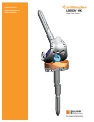
3.5mm Posterior Distal Tibia Locking Plate• Scalloped to allow lag screw placement without<strong>com</strong>promising plate position• Contour facilitates a posterior approach to distaltibia fractures in the coronal plane• Consistent 1.5mm plate thickness• Left and right specific3.5mm Anterior Distal Tibia Locking Plate• Scalloped to allow lag screw placement without<strong>com</strong>promising plate position• Contour facilitates an anterior approach to distaltibia fractures in the coronal plane• Consistent 1.5mm plate thickness3.5mm Medial Distal Tibia Locking Plate• Smooth distal tip minimizes soft tissue irritationover the medial malleolus• 2.0mm – 1.5mm proximal to distal platethickness transition• Contour facilitates a medial approach to distaltibia fractures in the sagittal plane• Left and right specific9
3.5mm Posteromedial Proximal TibiaLocking Plate• Contoured to provide a stable buttress platformfor fractures of the medial tibial plateau• Consistent plate thickness:1.5mm = 4 hole2.0mm = 7 hole• Left and right specific3.5mm Lateral Proximal Tibia Locking Plate• Scalloped to allow lag screw placement without<strong>com</strong>promising plate position• 1.5mm – 2.0mm proximal to distal platethickness transition• Left and right specific• 3° AP radius of curvature optimizes platecoverage down the tibial shaft and proximalscrew position10
PERI-LOC <strong>VLP</strong> screws• Standard 2.5mm hex head recess for all screws• Low profile heads to reduce soft tissue irritation• Screw angulation in each plate hole:3.5mm Cortex: 20°3.5mm Locking: 15°5.0mm Osteopenia: 15°• Self-Tapping 2.7mm Cortex, 3.5mm Cortex and3.5mm Locking Screws• 5.0mm Osteopenia Screw (fully and partiallythreaded) provides superior purchase and<strong>com</strong>pression in poor quality bone stock• Standardized drill bits:2.7mm Drill Bit: 3.5mm and 5.0mm screws2.0mm Drill Bit: 2.7mm screws3.5mm Cortex Screw3.5mm Locking Screw5.0mm Osteopenia ScrewFully Threaded5.0mm Osteopenia ScrewPartially Threaded2.7mm Cortex Screw11
Surgical techniqueFracture reductionArticular fracture <strong>com</strong>ponents must beanatomically reduced prior to plate applicationand screw insertion. Reduction aids should beplaced so as not to interfere with final plateplacement. Reduce and provisionally securefracture fragments using:• K-wires*1.25mm x 150mm (7116-1012)1.6mm x 150mm (7116-1016)2.0mm x 150mm (7116-1020)Note If K-wires are to be inserted throughthe holes on a PERI-LOC <strong>VLP</strong> locking platefor the purpose of provisional fixation, it isre<strong>com</strong>mended that 1.6mm K-wires be used.• Provisional Fixation Pins*2.7mm x 14mm (7117-1228)2.7mm x 25mm (7117-1229)2.7mm x 40mm (7117-1230)Note Provisional Fixation Pins may be insertedon power, but should always be seatedmanually in order to avoid stripping of thethreads and loss of purchase.• Ball Spike Pusher (7117-1210)**• Reduction Forceps**Ball Spike Reduction Clamp, Medium (7117-1212)Ball Spike Reduction Clamp, Large (7117-1213)Ratchet Reduction Forceps (7117-0044,7117-3370, 7117-3377, 7117-3378)Fibula Clamp (7117-1211)*Located in the PERI-LOC <strong>VLP</strong> Instrument Tray**Located in the PERI-LOC Periarticular Forceps Tray12
• Ball Spike Reduction Clamp:Assemble either the 15mm or 25mm SpikedWasher (7117-1220, 7117-1221)* to the ball spikeclamp by pushing the tip of the clamp into thewasher until it snaps on.Care should be taken when handling theclamps and spiked washers to avoid thesharpened tips.If the ball spike clamp is to be used with a plate,insert one of the tips into the desired plate holeand engage the other tip with the bone on theopposite cortex. If using a spiked washer on thefar-side clamp tip, ensure that the spikesare against bone.*Located in the PERI-LOC Periarticular Forceps Tray13
3.5mm Lateral Distal FibulaPatient positioningPlace the patient in the supine position on aradiolucent table. Confirm unimpeded APand lateral visualization of the distal fibulaunder fluoroscopy.Plate selectionFollowing fracture reduction, select the3.5mm Lateral Distal Fibula Locking Plate thatbest ac<strong>com</strong>modates patient anatomy andfracture pattern.Note The PERI-LOC <strong>VLP</strong> 3.5mm Lateral DistalFibula Locking Plate Preoperative Template(7118-1180) is available to assist withpre-operative radiographic planning.PERI-LOC <strong>VLP</strong> 3.5mm Lateral Distal Fibula Locking PlatePreoperative TemplateCat. No. 7118-1180Plate positioningThe plate lies along the lateral aspect of thedistal fibula with the distal screw clustercovering the lateral malleolus. Provisionally fixthe plate to bone using Reduction Forcepsand/or Provisional Fixation Pins and proceedwith screw insertion as desired.14
3.5mm PosterolateralDistal FibulaPatient positioningPlace the patient in the supine position on aradiolucent table. Confirm unimpeded APand lateral visualization of the distal fibulaunder fluoroscopy.Plate selectionFollowing fracture reduction, select the 3.5mmPosterolateral Distal Fibula Locking Plate thatbest ac<strong>com</strong>modates patient anatomy andfracture pattern.Note The PERI-LOC <strong>VLP</strong> 3.5mm PosterolateralDistal Fibula Locking Plate PreoperativeTemplate (7118-1199) is available to assist withpre-operative radiographic planning.PERI-LOC <strong>VLP</strong> 3.5mm Posterolateral Distal Fibula LockingPlate Preoperative TemplateCat. No. 7118-1199Plate positioningThe plate lies along the posterolateral aspect ofthe distal fibula. Provisionally fix the plate tobone using Reduction Forceps and/orProvisional Fixation Pins and proceed withscrew insertion as desired.15
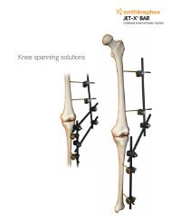
3.5mm Lateral Proximal TibiaPatient positioningPlace the patient in the supine position on aradiolucent table. Confirm unimpeded APand lateral visualization of the proximal tibiaunder fluoroscopy.Plate selectionFollowing fracture reduction, select the3.5mm Lateral Proximal Tibia Locking Plate thatbest ac<strong>com</strong>modates patient anatomy andfracture pattern.Note The PERI-LOC <strong>VLP</strong> 3.5mm LateralProximal Tibia Locking Plate PreoperativeTemplate (7118-1182) is available to assist withpre-operative radiographic planning.PERI-LOC <strong>VLP</strong> 3.5mm Lateral Proximal Tibia Locking PlatePreoperative TemplateCat. No. 7118-1182Plate positioningThe Lateral Proximal Tibia Positioning Guide*(7117-1216, 7117-1217) allows visualization ofplate position and provides a template forindependent lag screw placement in theproximal tibia prior to plate application.1.6mm x 150mm K-wires can be insertedthrough the two proximal holes in the guideto aid with provisional fixation and fracturereduction. Remove the positioning guidefollowing K-wire insertion. If desired, theselected plate may then be applied to bonedirectly over the wires.The plate sits along the lateral aspect of theproximal tibia. A 5° posterior tilt aligns theproximal row of screws with the contour of thelateral tibial condyle. Plate coverage extendingdown the shaft is maximized by a 3° sagittalcurve in the plate’s proximal segment. Aproximal row of scallops facilitates externallag screw placement without <strong>com</strong>promisingplate position.Provisionally fix the plate to bone using K-wires,Ball Spike Reduction Clamps and/or ProvisionalFixation Pins and proceed with screw insertionas desired.*The positioning guides are left/right specific16
3.5mm PosteromedialProximal TibiaPatient positioningPlace the patient in the supine position on aradiolucent table. Confirm unimpeded APand lateral visualization of the proximal tibiaunder fluoroscopy.Plate selectionFollowing fracture reduction, select the 3.5mmPosteromedial Proximal Tibia Locking Plate thatbest ac<strong>com</strong>modates patient anatomy andfracture pattern.PERI-LOC <strong>VLP</strong> 3.5mm Posteromedial Proximal Tibia LockingPlate Preoperative TemplateCat. No. 7118-1196Note The PERI-LOC <strong>VLP</strong> 3.5mm PosteromedialProximal Tibia Locking Plate PreoperativeTemplate (7118-1196) is available to assist withpre-operative radiographic planning.Plate positioningThe plate sits along the posteromedial aspect ofthe proximal tibia. Scallops at the top of theplate facilitate lag screw placement for jointsurface reconstruction without <strong>com</strong>promisingplate position.Provisionally fix the plate to bone using K-wires,Ball Spike Reduction Clamps and/or ProvisionalFixation Pins and proceed with screw insertionas desired.17
3.5mm Medial Distal TibiaPatient positioningPlace the patient in the supine position on aradiolucent table. Confirm unimpeded APand lateral visualization of the distal tibiaunder fluoroscopy.Plate selectionFollowing fracture reduction, select the3.5mm Medial Distal Tibia Locking Plate thatbest ac<strong>com</strong>modates patient anatomy andfracture pattern.Note The PERI-LOC <strong>VLP</strong> 3.5mm Medial DistalTibia Locking Plate Preoperative Template(7118-1181) is available to assist withpre-operative radiographic planning.PERI-LOC <strong>VLP</strong> 3.5mm Medial Distal Tibia Locking PlatePreoperative TemplateCat. No. 7118-1181Plate positioningThe plate sits along the medial aspect of thedistal tibia with the distal most screw holespositioned just superior to the plafond.Provisionally fix the plate to bone using K-wires,Ball Spike Reduction Clamps, Reduction Forcepsand/or Provisional Fixation Pins and proceedwith screw insertion as desired.18
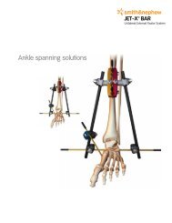
3.5mm Anterior Distal TibiaPatient positioningPlace the patient in the supine position on aradiolucent table. Confirm unimpeded APand lateral visualization of the distal tibiaunder fluoroscopy.Plate selectionFollowing fracture reduction, select the3.5mm Anterior Distal Tibia Locking Plate thatbest ac<strong>com</strong>modates patient anatomy andfracture pattern.Note The PERI-LOC <strong>VLP</strong> 3.5mm AnteriorDistal Tibia Locking Plate PreoperativeTemplate (7118-1197) is available to assist withpre-operative radiographic planning.PERI-LOC <strong>VLP</strong> 3.5mm Anterior Distal Tibia Locking PlatePreoperative TemplateCat. No. 7118-1197Plate positioningThe Anterior Distal Tibia Positioning Guide(7117-1218) allows visualization of plate positionand provides a template for independent lagscrew placement in the distal tibia prior to plateapplication. 1.6mm x 150mm K-wires can beinserted through the two distal holes in theguide to aid with provisional fixation and fracturereduction. Remove the positioning guidefollowing K-wire insertion. If desired, theselected plate may then be applied to bonedirectly over the wires.The plate sits along the anterior aspect of thedistal tibia with its distal tip resting just superiorto the tibial plafond. Distal scallops facilitatelag screw placement without <strong>com</strong>promisingplate position.Provisionally fix the plate to bone using K-wires,Ball Spike Reduction Clamps, Reduction Forcepsand/or Provisional Fixation Pins and proceedwith screw insertion as desired.19
3.5mm Posterior Distal TibiaPatient positioningPlace the patient in the prone position on aradiolucent table. Confirm unimpeded APand lateral visualization of the distal tibiaunder fluoroscopy.Plate selectionFollowing fracture reduction, select the3.5mm Posterior Distal Tibia Locking Plate thatbest ac<strong>com</strong>modates patient anatomy andfracture pattern.Note The PERI-LOC <strong>VLP</strong> 3.5mm PosteriorDistal Tibia Locking Plate Preoperative Template(7118-1198) is available to assist withpre-operative radiographic planning.PERI-LOC <strong>VLP</strong> 3.5mm Posterior Distal Tibia Locking PlatePreoperative TemplateCat. No. 7118-1198Plate positioningThe plate sits along the posterior aspect of thedistal tibia with its distal tip resting just superiorto the tibial plafond. Distal scallops facilitatelag screw placement without <strong>com</strong>promisingplate position.Provisionally fix the plate to bone using K-wires,Ball Spike Reduction Clamps, Reduction Forcepsand/or Provisional Fixation Pins and proceedwith screw insertion as desired.20
3.5mm Locking Screw and5.0mm Osteopenia ScrewInsert the Universal Drill Guide Handle with2.7mm Variable Angle Drill Guide (7117-1219)into the desired screw hole. The drill guide iscorrectly aligned when its star-shaped tipengages with the five tabs in the hole. Adjustscrew trajectory by rotating the tip of thevariable angle drill guide 360° within the platehole and up to 15° in any direction. Drillaccordingly with either the Short or Long 2.7mmDrill Bit depending upon plate type and location.Note The 2.7mm x 3.5mm Drill Guide isavailable for placement of a 5.0mm Osteopeniascrew outside the plate. If inserting a 5.0mmOsteopenia screw through the plate as a lagscrew, the 2.7mm Variable Angle Drill Guideshould be used.Measure for screw length by reading theexposed calibrations off the drill or by using thedepth gauge. Depending upon the drill used,either the Standard or Long Depth Gauge willbe required.Note An additional 50mm must be added tothe length of the screw when using the2.7mm x 3.5mm Drill Guide with the Long2.7mm Drill Bit as the drill bit is not calibratedto the drill guide. For screws shorter than 50mmin length, use the Standard Depth Gauge.Insert the appropriate length 3.5mm Self-Tapping Locking Screw using the 1.7Nm TorqueLimiting Screwdriver* (7117-1238) and 2.5mmHexdriver Shaft (7117-0033, 7117-0169). Usageof the torque limiting screwdriver will preventover-insertion of the locking screw throughthe star-shaped plate hole. For insertion of a5.0mm Osteopenia screw, the 2.5mm HexScrewdriver is used.*The 1.7Nm Torque Limiting Screwdriver should be calibrated every six months to ensure optimal instrument performance22
Catalog informationPERI-LOC <strong>VLP</strong> Instrument SetSet No. 7181-2301Instrument CaseCat. No. Description7117-0404 PERI-LOC <strong>VLP</strong> Instrument Tray7117-0410 PERI-LOC <strong>VLP</strong> Instrument Tray Lid7117-0396 PERI-LOC <strong>VLP</strong> Drill CaddyInstrumentsCat. No. Description Qty7117-0043 Sharp Hook 17117-3369 Hohmann Retractor Bent 27117-0057 Hohmann Retractor Bent 8mm 27117-0095 Hohmann Retractor Bent 15mm 27117-0097 Periosteal Elevator, 6mm Curved 17117-0063 Wire Bending Pliers, 140mm 17117-3377 Reduction Forceps Broad 27117-3378 Reduction Forceps Serrated Jaws 27117-1219 2.7mm Variable Angle Drill Guide 17117-1222 Universal Drill Guide Handle 1with Quick Connect7117-1231 Standard Depth Gauge (6mm – 55mm) 17117-1232 Long Depth Gauge (6mm – 110mm) 17117-3528 AO – Trinkle 1Cat. No. Description Qty7117-3543 Tear Drop Screwdriver Handle 17117-1238 1.7Nm Torque 1Limiting Screwdriver7117-0029 2.5mm Hex Screwdriver, Small 17117-0031 Holding Sleeve 17117-1224 2.0mm X 2.7mm Drill Guide 17117-1225 2.7mm X 3.5mm Drill Guide 17117-1226 3.5mm Drill Guide 17117-1227 2.7mm Drill Guide 17117-1237 Screw Extractor 17117-1233 Plate Bending Irons 27117-3344 3.5mm Countersink 17117-0033 2.5mm Hexdriver Shaft – 100mm 27117-0169 2.5mm Hexdriver Shaft – 165mm 1<strong>VLP</strong> Disposable SetSet No. 7181-2302Cat. No. Description Qty7116-1012 1.25mm X 150mm K-wire 67116-1016 1.6mm X 150mm K-wire 67116-1020 2.0mm X 150mm K-wire 67117-1228 2.7mm X 14mm PF Pin 27117-1229 2.7mm X 25mm PF Pin 27117-1230 2.7mm X 40mm PF Pin 27117-3588 Short 2.0mm Drill Bit, 157mm 1Cat. No. Description Qty7117-3501 Long 2.0mm Drill Bit, 190mm 17117-3502 Short 2.7mm Drill Bit, 155mm 27117-3503 Long 2.7mm Drill Bit, 228mm 27117-3504 3.5mm Drill Bit, 155mm 27117-3366 2.7mm Tap 17117-3318 3.5mm Tap 125
Catalog informationPERI-LOC Periarticular Forceps SetSet No. 7181-2300Instrument CaseCat. No. Description7117-0411 PERI-LOC Periarticular Forceps Tray7117-0412 PERI-LOC Periarticular Forceps Tray LidInstrumentsCat. No. Description Qty7117-1210 Ball Spike Pusher 17117-1212 Ball Spike Reduction Clamp, Medium 17117-1213 Ball Spike Reduction Clamp, Large 17117-1220 15mm Spiked Washer 27117-1221 25mm Spiked Washer 27117-1211 Fibula Clamp 1Cat. No. Description Qty7117-0044 Reduction Forceps, w/ Ratchet 205mm 17117-3370 Reduction Forceps, w/ Bowed 1Ratchet 205mm7117-3377 Reduction Forceps Broad 27117-3378 Reduction Forceps Serrated Jaws 226
PERI-LOC <strong>VLP</strong> Implant SetSet No. 7181-2200Instrument CaseCat. No.Description7117-0394 PERI-LOC <strong>VLP</strong> Implant Tray7117-0406 PERI-LOC <strong>VLP</strong> Implant Tray Lid7117-0413 PERI-LOC <strong>VLP</strong> Proximal Tibia Locking Plate Tray7117-0414 PERI-LOC <strong>VLP</strong> Proximal Tibia Locking Plate Tray Lid7117-0415 PERI-LOC <strong>VLP</strong> Distal Tibia/Fibula Locking Plate Tray7117-0416 PERI-LOC <strong>VLP</strong> Distal Tibia/Fibula Locking PlateTray LidCat. No. Description7117-0402 PERI-LOC <strong>VLP</strong> Screw Caddy7117-0408 PERI-LOC <strong>VLP</strong> Screw Caddy Lid7117-0417 PERI-LOC <strong>VLP</strong> Auxiliary Screw Caddy7117-0418 PERI-LOC <strong>VLP</strong> Auxiliary Screw Caddy LidInstrumentsCat. No. Description Qty7117-1216 Lateral Proximal Tibia Positioning 1Guide, Right7117-1217 Lateral Proximal Tibia Positioning 1Guide, Left7117-1218 Anterior Distal Tibia Positioning Guide 17117-0002 Screw Forcep 127
Catalog informationImplants3.5mm PosteromedialProximal Tibia Locking PlatesCat. No. Description Length7282-0104 4H, Left 64mm7282-0107 7H, Left 98mmCat. No. Description Length7282-0204 4H, Right 64mm7282-0207 7H, Right 98mm3.5mm Lateral Proximal TibiaLocking PlatesCat. No. Description Length7282-0304 4H, Left 68mm7282-0306 6H, Left 93mmCat. No. Description Length7282-0404 4H, Right 68mm7282-0406 6H, Right 93mm3.5mm Posterior Distal TibiaLocking PlatesCat. No. Description Length7282-0203 3H, Left 47mm7282-0205 5H, Left 72mmCat. No. Description Length7282-0303 3H, Right 47mm7282-0305 5H, Right 72mm3.5mm Anterior Distal TibiaLocking PlatesCat. No. Description Length7282-0503 3H 74mm7282-0506 6H 107mm3.5mm Medial Distal TibiaLocking PlatesCat. No. Description Length7282-0603 3H, Left 89mm7282-0606 6H, Left 127mmCat. No. Description Length7282-0703 3H, Right 89mm7282-0706 6H, Right 127mm3.5mm Posterolateral DistalFibula Locking PlatesCat. No. Description Length7282-0805 5H, Left 62mm7282-0806 6H, Left 74mm7282-0807 7H, Left 86mmCat. No. Description Length7282-0905 5H, Right 62mm7282-0906 6H, Right 74mm7282-0907 7H, Right 86mm28
3.5mm Lateral Distal FibulaLocking PlatesCat. No. Description Length7282-1003 3H, Left 59mm7282-1004 4H, Left 71mm7282-1005 5H, Left 83mm7282-1007 7H, Left 107mm7282-1009 9H, Left 131mm7282-1011 11H, Left 155mmCat. No. Description Length7282-2003 3H, Right 59mm7282-2004 4H, Right 71mm7282-2005 5H, Right 83mm7282-2007 7H, Right 107mm7282-2009 9H, Right 131mm7282-2011 11H, Right 155mm3.5mm One-Third LockingTubular PlatesCat. No. Description Length7282-3005 5H 62mm7282-3006 6H 74mm7282-3007 7H 86mmCat. No. Description Length7280-3008* 8H 98mm7280-3010* 10H 122mm7280-3012* 12H 146mm2.7mm Self-TappingCortex ScrewsCat. No. Length7182-3010 10mm7182-3012 12mm7182-3014 14mm7182-3016 16mm7182-3018 18mm7182-3020 20mm7182-3022 22mm7182-3024 24mm7182-3026 26mm7182-3028 28mm7182-3030 30mm7182-3032 32mm7182-3034 34mmCat. No. Length7182-3036 36mm7182-3038 38mm7182-3040 40mm7182-3042 42mm7182-3044 44mm7182-3046 46mm7182-3048 48mm7182-3050 50mm7182-3055 55mm7182-3060 60mm7182-3065 65mm7182-3070 70mm2.7mm Cortex Screws(Non Self-Tapping)Cat. No. Length7182-3310** 10mm7182-3312** 12mm7182-3314** 14mm7182-3316** 16mmCat. No. Length7182-3318** 18mm7182-3320** 20mm7182-3322** 22mm*Available sterile only**Optional screws29
Catalog information3.5mm Self-TappingLocking ScrewsCat. No. Length7182-1206 6mm7182-1208 8mm7182-1210 10mm7182-1212 12mm7182-1214 14mm7182-1216 16mm7182-1218 18mm7182-1220 20mm7182-1222 22mm7182-1224 24mm7182-1226 26mm7182-1228 28mmCat. No. Length7182-1230 30mm7182-1232 32mm7182-1234 34mm7182-1236 36mm7182-1238 38mm7182-1240 40mm7182-1242 42mm7182-1244 44mm7182-1246 46mm7182-1248 48mm7182-1250 50mm7182-1255 55mmCat. No. Length7182-1260 60mm7182-1265 65mm7182-1270 70mm7182-1275 75mm7182-1280 80mm7180-1285* 85mm7180-1290* 90mm7180-1295* 95mm7180-1296* 100mm7180-1297* 105mm7180-1298* 110mm3.5mm Self-TappingCortex ScrewsCat. No. Length7182-1306 6mm7182-1308 8mm7182-1310 10mm7182-1312 12mm7182-1314 14mm7182-1316 16mm7182-1318 18mm7182-1320 20mm7182-1322 22mm7182-1324 24mm7182-1326 26mm7182-1328 28mmCat. No. Length7182-1330 30mm7182-1332 32mm7182-1334 34mm7182-1336 36mm7182-1338 38mm7182-1340 40mm7182-1342 42mm7182-1344 44mm7182-1346 46mm7182-1348 48mm7182-1350 50mm7182-1355 55mmCat. No. Length7182-1360 60mm7182-1365 65mm7182-1370 70mm7182-1375 75mm7182-1380 80mm7180-1385* 85mm7180-1390* 90mm7180-1395* 95mm7180-1396* 100mm7180-1397* 105mm7180-1398* 110mm3.5mm Cortex Screws(Non Self-Tapping)Cat. No. Length7182-3510** 10mm7182-3512** 12mm7182-3514** 14mm7182-3516** 16mmCat. No. Length7182-3518** 18mm7182-3520** 20mm7182-3522** 22mm*Available sterile only**Optional screws30
5.0mm Osteopenia Screws,Fully ThreadedCat. No. Length7182-2010 10mm7182-2012 12mm7182-2014 14mm7182-2016 16mm7182-2018 18mm7182-2020 20mm7182-2022 22mm7182-2024 24mm7182-2026 26mm7182-2028 28mm7182-2030 30mm7182-2032 32mmCat. No. Length7182-2034 34mm7182-2036 36mm7182-2038 38mm7182-2040 40mm7182-2042 42mm7182-2044 44mm7182-2046 46mm7182-2048 48mm7182-2050 50mm7182-2055 55mm7182-2060 60mm7182-2065 65mmCat. No. Length7182-2070 70mm7182-2075 75mm7182-2080 80mm7180-2085* 85mm7180-2090* 90mm7180-2095* 95mm7180-2096* 100mm7180-2097* 105mm7180-2098* 110mm5.0mm Osteopenia Screws,Partially ThreadedCat. No. Length7182-1126 26mm7182-1128 28mm7182-1130 30mm7182-1132 32mm7182-1134 34mm7182-1136 36mm7182-1138 38mm7182-1140 40mm7182-1142 42mmCat. No. Length7182-1144 44mm7182-1146 46mm7182-1148 48mm7182-1150 50mm7182-1155 55mm7182-1160 60mm7182-1165 65mm7182-1170 70mm7182-1175 75mmCat. No. Length7182-1180 80mm7180-1185* 85mm7180-1190* 90mm7180-1195* 95mm7180-1196* 100mm7180-1197* 105mm7180-1198* 110mmWasher, 7.0mm Outer DiameterCat. No. 7114-3107*Available sterile only31
Notes32
OrthopaedicsSmith & Nephew, Inc.1450 Brooks RoadMemphis, TN 38116USAwww.smith-nephew.<strong>com</strong>Telephone: 1-901-396-2121Information: 1-800-821-5700Orders/Inquiries: 1-800-238-7538Trademark of Smith & Nephew. Reg. US Pat. & TM Off.©Copyright 2010 Smith & Nephew, Inc. All rights reserved.7118-1201 REV0 02/10