Ordering Guide for Factory-Installed Options - ORBIT/FR, Inc.
Ordering Guide for Factory-Installed Options - ORBIT/FR, Inc.
Ordering Guide for Factory-Installed Options - ORBIT/FR, Inc.

You also want an ePaper? Increase the reach of your titles
YUMPU automatically turns print PDFs into web optimized ePapers that Google loves.
132<br />
> <strong>Ordering</strong> <strong>Guide</strong><br />
<strong>for</strong> <strong>Factory</strong>-<strong>Installed</strong> <strong>Options</strong><br />
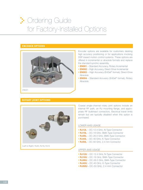
encoder options<br />
EN001<br />
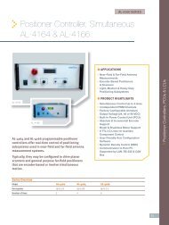
rotary joint options<br />
(Left to Right) RJ40, RJ18, RJ12<br />
Encoder options are available <strong>for</strong> customers desiring<br />
high accuracy positioning or <strong>for</strong> applications involving<br />
DSP-based motion control systems. These options are<br />
offered in incremental or absolute <strong>for</strong>mats and replace<br />
the standard synchro assembly.<br />
• EN001 – Standard Accuracy, Rotary <strong>Inc</strong>remental<br />
• EN002 – High Accuracy, Direct-Drive <strong>Inc</strong>remental<br />
• EN003 – High Accuracy (EnDat ® <strong>for</strong>mat), Direct-Drive<br />
Absolute<br />
• EN004 – Standard Accuracy (EnDat ® <strong>for</strong>mat), Rotary<br />
Absolute<br />
Coaxial single-channel rotary joint options include an<br />
internal RF path, an RJ mounting fl ange, and appropriate<br />
RF bulkhead connectors. Electrical travel limits<br />
remain but are typically disabled when this option is<br />
purchased.<br />
LOWER AXIS USAGE<br />
• RJ12L – DC-12.4 GHz, N-Type Connector<br />
• RJ18L – DC-18 GHz, SMA-Type Connector<br />
• RJ26L – DC-26.5 GHz, SMA-Type Connector<br />
• RJ40L – DC-40 GHz, K-Type Connector<br />
• RJ50L – DC-50 GHz, 2.4 mm Connector<br />
UPPER AXIS USAGE<br />
• RJ12U – DC-12.4 GHz, N-Type Connector<br />
• RJ18U – DC-18 GHz, SMA-Type Connector<br />
• RJ26U – DC-26.5 GHz, SMA-Type Connector<br />
• RJ40U – DC-40 GHz, K-Type Connector<br />
• RJ50U – DC-50 GHz, 2.4 mm Connector
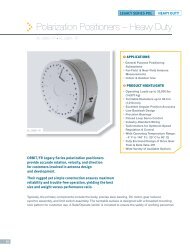
slip ring options<br />
SR402<br />
These options support unrestricted (continuous) rotation<br />
of positioner axes. They can be ordered in two<br />
confi gurations: integrated wiring <strong>for</strong> upper positioner<br />
axes and/or point-to-point thru-paths <strong>for</strong> customer<br />
use. Please specify the desired confi guration when<br />
ordering this option. These options include internal wiring<br />
and MS bulkhead connectors. Electrical travel limits<br />
remain but are typically disabled when this option is<br />
purchased.<br />
internal harnessing option<br />
This option supports restricted (non-continuous) rotation<br />
of positioner axes. It can be ordered in two confi gurations:<br />
integrated wiring <strong>for</strong> upper positioner axes and/or<br />
point-to-point thru-paths <strong>for</strong> customer use. Please specify<br />
the desired confi guration when ordering this option.<br />
connector <strong>for</strong>mat option<br />
These options specify available connector <strong>for</strong>mats <strong>for</strong><br />
light, medium, and heavy duty positioners. Please specify<br />
the desired confi guration when ordering this option.<br />
LOWER AXIS USAGE<br />
• SR051L – 5 Contact<br />
• SR101L – 10 Contact<br />
• SR201L – 20 Contact<br />
• SR301L – 30 Contact<br />
• SR402L – 40 Contact<br />
• SR502L – 50 Contact<br />
• SR602L – 60 Contact<br />
• SR512L – 50 Contact (High Current)<br />
• SR812L – 80 Contact (High Current)<br />
UPPER AXIS USAGE<br />
• SR051U – 5 Contact<br />
• SR101U – 10 Contact<br />
• SR201U – 20 Contact<br />
• SR301U – 30 Contact<br />
• SR402U – 40 Contact<br />
• SR502U – 50 Contact<br />
• SR602U – 60 Contact<br />
This option includes an internal wiring harness and MS<br />
bulkhead connectors. Electrical travel limits typically<br />
remain enabled when this option is purchased.<br />
• EX002 – Internal Harnessing Option – Up to 60<br />
Contacts<br />
• CF001 – Connector Format Option – Rear Panel<br />
Connector Location<br />
• CF002 – Connector Format Option – Single Connector<br />
Format<br />
133
134<br />
thru-hole options<br />
TH002<br />
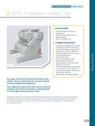
stow-lock options<br />
ST002L<br />
leveling options<br />
LS002<br />
These options provide a protective housing through the<br />
center of selected positioner models. They are available<br />
in either indoor or outdoor confi gurations. Applications<br />
<strong>for</strong> this option include cable pathways and stationary<br />
fi xtures which pass through the center of the axis.<br />
Electrical travel limits typically remain enabled when this<br />
option is purchased. Consult your local sales representative<br />
when confi guring this option.<br />
• TH002 - Indoor Rated <strong>for</strong> Light & Medium Duty<br />
Positioners<br />
• TH002-HD - Indoor Rated <strong>for</strong> Heavy Duty<br />
Positioners<br />
• TH003 - Outdoor Rated <strong>for</strong> Light & Medium Duty<br />
Positioners<br />
• TH003-HD - Outdoor Rated <strong>for</strong> Heavy Duty<br />
Positioners<br />
This option provides a stow-lock pin mechanism which<br />
mechanically locks the specifi ed rotary axis to prevent<br />
excessive gear tooth loading. Typical applications include<br />
gear-train protection when storing/handling/shipping<br />
the positioner or whenever axis movement must<br />
be avoided (ex: when mounting a vehicle). Stow-locks<br />
operate in one of two positions: stowed in housing or<br />
installed in the axis. When the stow-lock pin is removed<br />
from its housing and installed into the positioner, a<br />
special circuit breaker (normally closed – N.C.) causes<br />
an electrical shutdown to prevent operation. Stow-locks<br />
are typically installed at 0º position. Special positions are<br />
available. Consult your local sales representative when<br />
confi guring this option.<br />
• ST002U – Upper Azimuth Axis<br />
• ST002E – Elevation Axis<br />
• ST002L – Lower Azimuth Axis<br />
Leveling options provide easy, quick and accurate<br />
leveling when installing medium and large sized positioners<br />
on uneven surfaces. They are available in varying<br />
quantities depending on the positioner model. Consult<br />
your local sales representative when confi guring this<br />
option.<br />
• LS001 – Leveling Screw Set, Medium Duty<br />
• LS002 - Leveling Screw Set, Heavy Duty
mounting thread options<br />
These options are available <strong>for</strong> applications requiring<br />
localized confi gurations.<br />
• MM002 - Metric Threads in Mounting Hole Interface<br />
> M6-1 – Replaces 1/4–20 UNC<br />
> M10-1.5 – Replaces 3/8-16 UNC<br />
> M12-1.75 – Replaces ½-11 UNC<br />
> M16-2 – Replaces 5/8-11 UNC<br />
> M20-2.5 – Replaces ¾-10UNC<br />
*Thread depth is 1.25 to 1.5 times larger than thread diameter.<br />
interlock protection circuit options<br />
Interlock circuits can be special-ordered <strong>for</strong> applications<br />
in which the design calls <strong>for</strong> preventing the operation of<br />
a specifi c axis while another axis is parked in a specifi c<br />
travel region. Applications include confi gurations utilizing<br />
model towers in which the interlocks are designed to<br />
prevent the model tower from colliding with a surface.<br />
Other applications include overload protection and safety<br />
work zones.<br />
base-riser options<br />
BR002<br />
• MM003 – Third Party Mounting Hole Interface<br />
Replication - Consult your local sales representative<br />
with specifi c bolt circle and thread requirements.<br />
• IC001 – Interlock Circuit, Medium Duty<br />
• IC002 – Interlock Circuit, Heavy Duty<br />
Base-risers can be special-ordered <strong>for</strong> applications in<br />
which a positioner must be located at a specifi c height<br />
above its main mounting surface. They are typically<br />
the same diameter as the positioner’s base and are<br />
constructed of the same material, steel or aluminum, as<br />
the positioner itself. Some base-risers can be designed<br />
<strong>for</strong> specifi c applications by including features such as<br />
lifting hooks, <strong>for</strong>k lift provisions, thru-holes, hatches,<br />
and ladders. Base-risers are typically constructed in a<br />
way that does not limit the positioner’s total capacity<br />
and overall specifi cations. Important parameters include<br />
overall capacity, diameter, and height. Consult your local<br />
sales representative when confi guring this option.<br />
• BR001 – Base-Riser, Medium Duty<br />
• BR002 – Base-Riser, Heavy Duty<br />
135
136<br />
wedge options<br />
WG002<br />
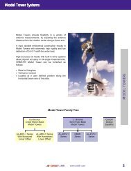
counterweight options<br />
Counterweights<br />
Wedge options can be special-ordered <strong>for</strong> applications<br />
in which the confi guration requires the positioner to be<br />
pre-tilted. Applications include downward tilt of Roll/<br />
EL positioners in which the wedge’s resulting tilt shifts<br />
the elevation travel beyond its normal downward-look<br />
angle. Wedges are constructed of the same material,<br />
steel or aluminum, as the positioner or base-riser and<br />
in a way that does not limit the positioner assembly’s<br />
total capacity and overall specifi cations. Important parameters<br />
include tilt angle and overall height and width.<br />
Consult your local sales representative when confi guring<br />
this option.<br />
• WG001 – Wedge, Medium Duty<br />
• WG002 – Wedge, Heavy Duty<br />
Counterweights can be special-ordered <strong>for</strong> applications<br />
in which the load is counter-balanced, optimizing<br />
torque and motion control. They typically vary by weight<br />
and length and are constructed of the same material,<br />
steel or aluminum, as the positioner itself. Counterweights<br />
add weight to the overall assembly and sometimes<br />
restrict travel. Important parameters include overall<br />
length, adjustable weight plates, indoor or outdoor use,<br />
and positioner confi guration. Consult your local sales<br />
representative when confi guring this option.<br />
• CW001 – Counterweight Assembly, Medium Duty<br />
• CW002 – Counterweight Assembly, Heavy Duty