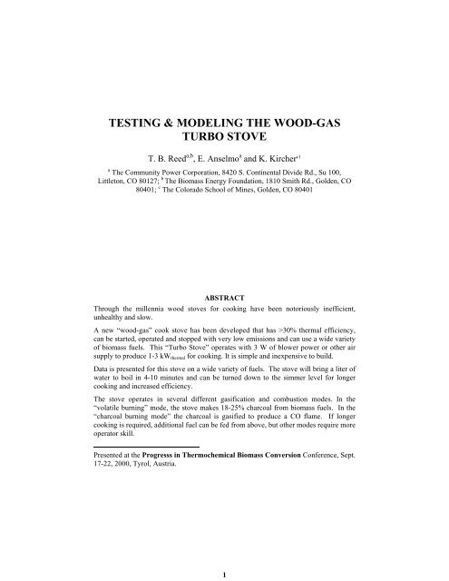
TESTING & MODELING THE WOOD-GAS TURBO STOVE
TESTING & MODELING THE WOOD-GAS TURBO STOVE
TESTING & MODELING THE WOOD-GAS TURBO STOVE

Create successful ePaper yourself
Turn your PDF publications into a flip-book with our unique Google optimized e-Paper software.
<strong>TESTING</strong> & <strong>MODELING</strong> <strong>THE</strong> <strong>WOOD</strong>-<strong>GAS</strong><br />
<strong>TURBO</strong> <strong>STOVE</strong><br />
T. B. Reed a,b , E. Anselmo a and K. Kircher c1<br />
a The Community Power Corporation, 8420 S. Continental Divide Rd., Su 100,<br />
Littleton, CO 80127; b The Biomass Energy Foundation, 1810 Smith Rd., Golden, CO<br />
80401; c The Colorado School of Mines, Golden, CO 80401<br />
ABSTRACT<br />
Through the millennia wood stoves for cooking have been notoriously inefficient,<br />
unhealthy and slow.<br />
A new “wood-gas” cook stove has been developed that has >30% thermal efficiency,<br />
can be started, operated and stopped with very low emissions and can use a wide variety<br />
of biomass fuels. This “Turbo Stove” operates with 3 W of blower power or other air<br />
supply to produce 1-3 kW thermal for cooking. It is simple and inexpensive to build.<br />
Data is presented for this stove on a wide variety of fuels. The stove will bring a liter of<br />
water to boil in 4-10 minutes and can be turned down to the simmer level for longer<br />
cooking and increased efficiency.<br />
The stove operates in several different gasification and combustion modes. In the<br />
“volatile burning” mode, the stove makes 18-25% charcoal from biomass fuels. In the<br />
“charcoal burning mode” the charcoal is gasified to produce a CO flame. If longer<br />
cooking is required, additional fuel can be fed from above, but other modes require more<br />
operator skill.<br />
Presented at the Progresss in Thermochemical Biomass Conversion Conference, Sept.<br />
17-22, 2000, Tyrol, Austria.<br />
1
For a new stove to be accepted it must fit the fuel supply, cooking practices ,<br />
construction methods and commercial infrastructure of each country. Therefore, it must<br />
be possible to make a variety of stoves and requires understanding of the basic<br />
mechanisms of gasification and combustion of “wood-gas”. A model of the wood-gas<br />
“Turbo Stove” is described based on the measured parameters in this paper.<br />
INTRODUCTION - <strong>WOOD</strong> COOKING VS <strong>WOOD</strong>-<strong>GAS</strong> COOKING<br />
Since the beginning of civilization wood and biomass have been used for cooking. Still,<br />
today over 2 billion people cook badly on slow, inefficient wood stoves that waste<br />
wood, cause health problems and destroy our forests. Electricity, gas or kerosene are<br />
preferred for cooking - when they can be obtained However, they are costly, contribute<br />
to global warming, and depend on having a suitable infrastructure often not available in<br />
developing countries<br />
In the last few decades, many improved wood stoves have been developed (the<br />
Chula, the Hiko, the Maendeleo, the Kuni Mbili, the Wendelbro, etc. 1 These new wood<br />
stoves are often more difficult to manufacture and they do not offer good control of<br />
cooking rate. They are often not accepted by the cooks for whom they are developed.<br />
Since 1850 the preferred means of cooking has been first gas, then electricity.<br />
Gas is still preferred by many cooks. Electric cooking can be 60% electric-efficient, but<br />
power generation and distribution is typically 30% efficient, yielding an overall<br />
efficiency of 18% for electric cooking.<br />
We have developed several simple, inexpensive wood-gas stoves which can<br />
bring the “joy of cooking with gas” to everyone while using a wide variety of renewable<br />
biomass fuels or coal. 2-4<br />
PRINCIPLES OF DOWNDRAFT <strong>GAS</strong>IFICATION FOR COOKING<br />
BIOMASS <strong>GAS</strong>IFICATION<br />
When biomass is burned with insufficient air in a gasifier, it makes a “producer gas”<br />
containing primarily CO, H 2 , CO 2 , H 2 O and CH 4 . Over a million gasifiers powered the<br />
civilian cars and trucks of Europe and Asia during WW II. Downdraft gasifiers are “tarburning,<br />
char-making” and are most suitable for biomass which contains 80% volatile<br />
material. Updraft, “char-burning, tar-making”, gasifiers are often used for coal which<br />
can be 80% char.<br />
In conventional downdraft gasifiers, air passes down through the fuel mass,<br />
then in the flaming pyrolysis zone burns the volatiles and tars while making charcoal<br />
and pyrolysis gas. The charcoal then further reduces the CO 2 and H 2 O combustion<br />
products back to CO and H 2 fuel.<br />
2
<strong>THE</strong> “INVERTED DOWNDRAFT <strong>GAS</strong>IFIER”<br />
In inverted (top burning) downdraft gasification air passes up through the fuel and<br />
meets the flaming pyrolysis zone where the reaction generates charcoal and fuel gas as<br />
shown in Fig. 1. 2,3<br />
Pyrolysis<br />
Gas<br />
Charcoal<br />
Zone<br />
Flaming<br />
Pyrolysis<br />
Zone<br />
Ungasified Wood<br />
Grate<br />
15 CM<br />
Primary<br />
Air Control<br />
Off<br />
Low<br />
High<br />
Medium<br />
Fig. 1-Natural convection gasifier Fig. 2-Forced convection Turbo<br />
stove made with 15 cm riser Stove with 3 kW flame from a 3 W<br />
sleeve 2,3<br />
blower 4<br />
NATURAL VS FORCED CONVECTION<br />
Natural convection provides poor mixing of air with fuel gases and can result in<br />
incomplete combustion, soot and emissions in open wood stoves. A chimney can supply<br />
1 mm water pressure per meter of height. Addition of a chimney for cooking can greatly<br />
improve wood combustion in closed models, but also adds complication and requires<br />
wasting heat to operate.<br />
Forced convection provides good mixing and combustion for gas cooking and is widely<br />
used in homes and camping stoves. The 3 W blower used in the Turbo Stove provides<br />
7.5 mm water pressure and makes clean cooking possible.<br />
3
<strong>THE</strong> “<strong>TURBO</strong> <strong>STOVE</strong>”<br />
The Community Power Corporation and the Biomass Energy Foundation have<br />
developed a new “Turbo wood-gas stove” using forced draft from a 3 Watt blower. One<br />
design is shown in Fig. 2. It consists of an inverted gasifier close coupled to a burner<br />
section to mix air and gas and burn cleanly. A 3 Watt blower generates ~ 7 mm water<br />
column pressure, equivalent to the draft of a 7 meter chimney. We have made it from an<br />
outer 1 gal paint can, an inner burner can and a fuel magazine or with many other<br />
construction methods. 4 Several burners can be assembled to make a cooking “range”.<br />
An oven can be placed on one of the burners for oven heat.<br />
The stove can be started and operated indoors with no exhaust fans and no odor<br />
of burning wood. We have taken the stove to India and the Philippines and cooked with<br />
the Turbo Stove in small villages and on conference room desks with no odor. While the<br />
Turbo Stove currently uses a 12 Volt 3 Watt blower, the power could come from stored<br />
compressed air, bellows, wind-up generators, photovoltaic, thermophotovoltaic, windup<br />
motors, thermoelectric or other sources.<br />
CONSTUCTION AND OPERATING <strong>THE</strong> <strong>TURBO</strong> <strong>STOVE</strong><br />
<strong>THE</strong> RESEARCH <strong>TURBO</strong> <strong>STOVE</strong><br />
The research Turbo Stove shown in Fig.<br />
3 consists of<br />
• An inverted downdraft gasifier and<br />
fuel magazine<br />
• A combustion section which burns<br />
the gas<br />
• Supports for a pot<br />
• Regulated air supply for gasification<br />
and combustion<br />
as shown in Fig. 3. This permits<br />
independent adjustment of the air to the<br />
gasification section and the combustion<br />
section for optimizing cooking<br />
conditions at both high and low levels.<br />
The rate of heating and boiling was used<br />
to measure the heat transfer for cooking.<br />
Draft meters were used to measure the<br />
Water<br />
Calorimeter<br />
Gasification<br />
Air<br />
Digital Balance<br />
Turbo Stove<br />
Flames<br />
Air Jets<br />
Charcoal<br />
Burning<br />
Fuel<br />
Unburned<br />
Fuel<br />
Grate<br />
Combustion<br />
Air<br />
Flowmeters<br />
Compressor<br />
Fig. 3 - Research Turbo Stove, showing<br />
separate supplies for gasification and<br />
combustion air.<br />
4
pressure drop for gasification and for combustion (typically 0.25-0.75 mmw for<br />
gasification and 2.5 mmw water pressure for combustion).<br />
<strong>THE</strong> PROTOTYPE <strong>STOVE</strong><br />
Compressed air and flowmeters do not a practical stove make. We have also built the<br />
prototype stove shown in Fig. 2 that is easier to operate and less expensive. It permits<br />
adjusting the power level by adjusting the gasification air. Some of the data below were<br />
taken on the research and some on the prototype stove.<br />
STARTING AND OPERATING <strong>THE</strong> <strong>STOVE</strong>S<br />
In a typical run, the stove is filled with weighed pellets of the dry fuel of choice. A<br />
layer of starting chips, (chips, charcoal, or other porous materials soaked in alcohol, fat<br />
or kerosene) is placed on top. The blower is turned on and the starter chips are lit with a<br />
match. For the first few minutes the starter chips ignite the fuel below and make a bed<br />
of charcoal that the gas must pass through. In 1-5 minutes, depending on the fuel, the<br />
main fuel mass is ignited and burns downward regularly in flaming pyrolysis mode until<br />
the reaction zone reaches the grate, making charcoal as it goes. The test variables are<br />
shown in Fig. 4 for the research stove and Fig. 5 for the prototype stove.<br />
600<br />
500<br />
Weight vs Time, Run 103<br />
400<br />
Wt remaining- g<br />
300<br />
200<br />
100<br />
Startup<br />
High Power burn; 47<br />
l/m Combustion, 15<br />
l/m Gasification air<br />
Medium power,<br />
28 l/m<br />
combustion; 5<br />
l/m gasification<br />
air<br />
Low power burn; 17<br />
l/m Combustion, 3<br />
l/m Gasificationair<br />
Charcoal<br />
0<br />
0 10 20 30 40 50 60<br />
Time - min<br />
Fig. 4 – Typical operating data on the research Turbo Stove showing<br />
weight of fuel remaining vs time at high, medium and low power levels<br />
Table 1 – Air Fuel Ratios for gasification and combustion, power levels, turndown<br />
and superficial velocity for research stove<br />
5
FUEL <strong>GAS</strong>IF COMB- <strong>GAS</strong>IF COMB- POWER TURN- SUP<br />
RATE AIR USTION AIR/ USTION DOWN VEL<br />
AIR FUEL AIR/<br />
FUEL<br />
POWER g/m g/m g/m kW P/Pmax m/s<br />
Maximum 11.3 18.0 56.6 1.59 5.01 2.83 1.00 0.062<br />
Medium 7.1 6.0 34.0 0.84 4.79 1.78 0.63 0.028<br />
Low 4.6 3.5 21.7 0.75 4.73 1.15 0.41 0.017<br />
1000<br />
900<br />
PEANUT SHELL PELLETS - RUN 5/24/00<br />
Various<br />
800<br />
700<br />
600<br />
500<br />
Volatile Combustion<br />
Charcoal Combustion<br />
Gas to 1/2 turn Gas to 1 turn for CO flame<br />
Gas to 1/4 turn<br />
Gas 2 turns<br />
FUEL CONSUMED-g<br />
400<br />
300<br />
Startup<br />
WATER BOILED - g<br />
200<br />
100<br />
WATER TEMP - C<br />
0<br />
0 10 20 30 40 50 60 70<br />
Time - min<br />
6
TEST PROCEDURE<br />
In operation the Turbo Stove is operated on a balance and the loss of weight of fuel and<br />
water are recorded as test cooking progresses as shown in Figs. 4 and 5. The stages in<br />
cooking are shown in Table 2. In some cases the run is stopped after the flaming<br />
pyrolysis zone reaches the grate and the volatiles have been burned. However, at this<br />
point the charcoal begins to be gasified by the incoming air and cooking can continue<br />
until all the fuel is gone.<br />
DATA ON <strong>THE</strong> <strong>TURBO</strong> <strong>STOVE</strong>S<br />
BEHAVIOR OF VARIOUS FUELS<br />
A typical set of data for the research and prototype stove are shown in Figs 4 and 5 and<br />
data collected on these runs are shown in Tables 1 and 2.<br />
The Turbo Stove has been satisfactorily operated on dozens of fuels. The<br />
behavior of six fuels tested more extensively is shown in Table 3. In addition to many<br />
biomass forms, coal was also found to be very a satisfactory fuel for the Turbo Stove.<br />
Some of the tests done for this paper were made on “¼ inch” (6.2 mm) stove<br />
sawdust pellets, a readily available, high density, reproducible fuel except where<br />
otherwise noted. Table 1 and Fig 4 show data taken on stove pellet fuel made from<br />
sawdust. Pellets are widely marketed for pellet heating stoves in the U.S. for $2.50 for a<br />
20 kg bag. This would be sufficient to cook 40 typical meals. Figure 5 and Table 2 were<br />
made using peanut shell pellets, a potentially good fuel wherever peanuts are produced.<br />
FUEL CONSUMPTION RATE AND COOKING POWER<br />
The fuel consumption rate is a direct measure of cooking power, provided all the gas is<br />
subsequently burned in the burner section. The heating value of most biomass with 5-<br />
10% moisture (Denver dry) is ~18 kJ/g. The stove typically produces 20-25% charcoal<br />
after the volatiles have been burned. The charcoal typically has a higher heating value<br />
of ~24 kJ/g. In the tables the power level is calculated from these values. A gasification<br />
rate of 10 g/m gives 2.5 kW, comparable to the large burner on modern gas or electric<br />
stoves.<br />
TURNDOWN RATIO<br />
An important criteria for successful stove cooking is the “turndown ratio” of the stove.<br />
Initially the stove should develop high power to bring water or oils to cooking<br />
temperature. After cooking temperature is reached it is desirable to turn the power level<br />
down to just maintain that temperature. The turndown ratios for wood and peanut shell<br />
pellets are shown in Tables 1 and 2.<br />
Table 2 –Stages in test of peanut shell pellets (Fig. 4), showing flame intensity,<br />
water evaporated, turndown and efficiency at various stages of heating water<br />
7
TIME CONDITION <strong>GAS</strong>IFIC<br />
ATION<br />
AIR<br />
FUEL<br />
REM<br />
WAT-<br />
ER<br />
LOST<br />
HEAT<br />
USED<br />
HEA EFFIC FLAME TURN<br />
T TO IENC INTEN -<br />
POT Y SITY DOW<br />
N<br />
min Turns g g kJ kJ kW<br />
0.0 Startup 2 530 0<br />
1.0 Pot on flame 2 520 3300 909 28% 4.1 100%<br />
7.2 Rocking Boil 2 420<br />
13.5 Turn Down 1/2 310 230<br />
↓ Medium 1050 253 24% 3.2 78%<br />
19.0 Turn down 1/4 240 340<br />
↓ Low 1650 506 31% 2.3 56%<br />
31.0 Only<br />
charcoal left<br />
1 130 560<br />
↓ 2160 851 39% 1.1 28%<br />
64.0 Off 1 40 930<br />
SUMMARY NA 490 930 8160 2518 31% 2.1 31%<br />
It is desirable to be able to operate at lower power levels than maximum and a major<br />
advantage of the Turbo Stove is that it can be operated at lower powers reducing the air<br />
for gasification and burning less gas. For most biomass the energy content is 18 kJ/g for<br />
fuel with about 10% moisture. In the volatile burning mode the volatile energy content<br />
is about 15 kJ/g, while the 25% charcoal contains 24 kJ/g. Calculations included here<br />
have been made on this basis.<br />
BOILING EFFICIENCY<br />
There has been entirely too much emphasis placed on “cooking efficiency”, but it is<br />
certainly one importuned factor in evaluating stoves. Equally important is low<br />
emissions, high intensity and good turndown ratio.<br />
The data shown in Table 3 for boiling efficiency was calculated from the ratio of energy<br />
used for boiling water (in an 18 cm diameter pot filled with 1liter of water) to the fuel<br />
consumed after the water reached the boiling point until the end of volatile burning. It<br />
typically ranges from -40%, depending on fuel, length of boiling time, pot size and other<br />
factors.<br />
8
Table 3 – Operating and derived data for runs on selected fuels<br />
TEST FUEL 1<br />
PEANUT<br />
SHELL<br />
PELLETS<br />
<strong>WOOD</strong><br />
PELLETS<br />
COCO-<br />
NUT<br />
SHELL<br />
PALM<br />
NUT<br />
SHELL<br />
<strong>WOOD</strong><br />
CHIPS<br />
COAL<br />
Test Date 5/25 5/9 4/22 4/27 4/26 4/28<br />
FUEL DATA<br />
Moisture Content 2 6.4 6.5 6.2 6 7.8 3.1<br />
Fuel Wt. –g 500 500 305 150 180 260<br />
Fuel Density-g/cm 3<br />
(3)<br />
RUN DATA<br />
Volatile burn timemin<br />
0.58 0.64 0.48 0.26 0.265 1.69<br />
30 41 19 13 15 37<br />
Volatiles burned g 490 410 215 130 150 150<br />
Time to Boil min 7.2 7.0 13.0 8 6.0 10.0<br />
Charcoal yield - g 130 90.0 90.0 20 30.0 130.0<br />
Water boiled - g 930 850.0 220.0 100 145.0 850.0<br />
DERIVED DATA<br />
Charcoal Yield-% 4 26 18 29 13 17 50<br />
Boiling Efficiency 5 31 31.8 37.5 33 20 24<br />
Average Intensity 6 2.1 2.5 2.8 2.5 2.5 2.4<br />
Notes: (1) The peanut shell pellets were 3/8” diameter from Birdsong Peanuts, Georgia; the wood pellets are<br />
standard ¼ inch wood heat pellets from Ace Hardware; the coconut shells were obtained from the Philippines<br />
hammermilled to 1 com on an edge; the palm nut shells were obtained in Indonesia; the wood chips were<br />
mixed tree chips from Denver ~ 2 cm on an edge; the coal was bituminous from Denver crushed to 2 cm on an<br />
edge.<br />
(2) Moisture in wt %, wet basis; (3) Apparent fuel density calculated from magazine dimensions and weight;<br />
(4) Charcoal yield calculated from char remaining at end of run and initial fuel weight; (5) Boiling efficiency<br />
calculated from fuel consumed during steady boil, based on 15 kJ/g for biomass volatiles, 35 kJ/g for coal<br />
volatiles; (6) based on 15 kJ/g for volatiles and burn time of volatiles.<br />
EFFECT OF FUEL MOISTURE CONTENT<br />
The fuel moisture content is recommended to be
Turbo Stove quite satisfactorily. We believe that this is because it is necessary for each<br />
layer of fuel to ignite the next lower layer. When the layer is dry, the fire propagates<br />
easily, but with wet fuel more charcoal is consumed to dry the layer before the reaction<br />
can proceed. This is born out by the fact that with bone dry fuel charcoal often exceeds<br />
25%, but with 30% moisture fuel only 4% charcoal remained after the pyrolysis was<br />
complete.<br />
AIR-FUEL RATIOS FOR <strong>GAS</strong>IFICATION<br />
The air/fuel ratio is a very important criterion for solid, liquid and gas fuels<br />
since there is only one theoretical value that produces maximum flame temperature and<br />
minimum emissions.<br />
Table 1 shows the air/fuel ratio (based on the sum of gasification and<br />
combustion air) for three conditions, the maximum, medium and low output as 4.5-5.7.<br />
The theoretical value for “typical dry biomass is 6.3 but depends on fuel composition<br />
and moisture content.<br />
The air/fuel ratio is an important parameter in the clean gasification and combustion of<br />
all fuels including biomass, charcoal and coal. The Air/fuel ratio was measured for<br />
wood pellets in the research stove and is shown in Table 1.<br />
<strong>GAS</strong> HEATING VALUE<br />
The gas heating value of raw producer gas containing significant condensable volatiles<br />
(tars) is difficult to measure, since measurements are usually made at room temperature<br />
after the tars have been removed. The gas higher heating value varies with the air/fuel<br />
ratio used for gasification and the superficial velocity. We are in the process of<br />
measuring it, but we expect is to vary in the range 5-7 MJ/Nm 3 .<br />
DIFFERENT MODES OF <strong>TURBO</strong> <strong>STOVE</strong> OPERATION<br />
Cooking is typically a batch process and successful operation of the Turbo Stove<br />
requires the cook to estimate how long a particular task will require. If further cooking<br />
or water heating is required, there are several ways to extend the heating time.<br />
On startup, the gasifier converts the biomass fuel volatiles to gas which is<br />
burned and leaves behind up to 30% charcoal which can be saved or burned for<br />
additional cooking. In the stove described in Table 3 times of 19-37 min were recorded<br />
for the various fuels.<br />
After the volatiles have all been burned a dramatic change in the flame occurs<br />
and with the air then gasifies the charcoal to CO, giving a different flame and much<br />
hotter temperatures at the grate.<br />
If even longer cooking is required, more fuel can be added judiciously in an<br />
“updraft” mode in which charcoal combustion supplies heat to pyrolyse the new fuel..<br />
10
These other methods may require more operator skill and different design and<br />
construction.<br />
SAFETY<br />
Producer gas was the only gas fuel widely available until 1940 when natural gas<br />
pipelines became common. Since producer gas contains 10-30% CO, it is a real health<br />
hazard if the flame is extinguished or incomplete combustion occurs. (Smoky open fires<br />
and insufficient cooking fuel are also major health hazards in the world today.)<br />
Therefore it is necessary to mandate good practice in using the Turbo Stove. In the<br />
volatile combustion mode CO is a minor hazard because if the flame should go out, the<br />
copious smoke warns the operator to re-ignite the fire or move the stove outside.<br />
However, in the charcoal combustion mode the CO is odorless and could pose a health<br />
hazard.<br />
It is recommended that all stoves including the Turbo Stove should be operated under a<br />
hood carrying the cooking odors and possible stove emissions to the outside by natural<br />
or forced convection. That is the practice in most kitchens in developing countries today<br />
and should be followed as the rest of the world develops.<br />
<strong>MODELING</strong> <strong>THE</strong> <strong>TURBO</strong> <strong>STOVE</strong><br />
TAYLORING <strong>THE</strong> <strong>STOVE</strong> FOR VARIOUS APPLICATIONS<br />
For a new stove to be accepted it must fit the fuel supply, cooking practices,<br />
construction methods, size of servings and commercial infrastructure of each country.<br />
Therefore, it must be possible to make a variety of stoves and requires understanding of<br />
the basic mechanisms of gasification and combustion of “wood-gas”. For this reason it<br />
is desirable to have a complete model of the wood-gas stove from which new designs<br />
can be constructed with a minimum of testing.<br />
Optimization of stove behavior ultimately depends on reaching a maximum heat transfer<br />
to the cooking pot while minimizing emissions and soot. This is a multivariable<br />
problem and must be broken down into its component parts for solution.<br />
SUPERFICIAL VELOCITY<br />
The superficial velocity (SV) is defined as “gas production rate/cross section” and is<br />
measured in m/s, btu/ft2-hr, etc. It is an important figure of merit of gasifiers and<br />
combustors. Each device will have a maximum SV that it can operate at satisfactorily. In<br />
downdraft gasification the SV determines the intensity of the flaming pyrolysis reaction<br />
and so controls gas, charcoal and tar production. The World War II gasifiers typically<br />
operated at 0.1-1.0 m/s to produce low tar gas and consume most of the charcoal. 5<br />
The Turbo Stove operates in the range 0 to 0.06 gasification superficial velocity<br />
because at higher gas rates the charcoal is blown out of the top of the gasifier. The SV<br />
11
for three conditions are shown in Table 1 for the research gasifier operating on wood<br />
pellets.<br />
ESTABLISHING <strong>STOVE</strong> CRITERIA<br />
To model the stove it is necessary to define the application in terms of maximum power<br />
required, minimum burn time at full power and whether charcoal is desired as a byproduct.<br />
<strong>THE</strong> <strong>GAS</strong>IFICATION SECTION OF <strong>THE</strong> <strong>TURBO</strong> <strong>STOVE</strong><br />
The gasification section is relatively simple to model as shown in Table 4.<br />
From the burn time at full power one first calculates the fuel requirement, using 18 kJ/g<br />
for volatiles, 24kJ/g for the charcoal or 21 kJ/g for the fuel (adjusted to the moisture and<br />
ash content). The maximum power required determines the rate of production of gas, the<br />
air/fuel ratio determines the gasification air that must be supplied and the superficial<br />
velocity determines the diameter of the gasifier chamber.<br />
In Table 4 the fuel magazine diameter and height for a hypothetical 12 kW<br />
gasifier required to burn for 2 hours for community cooking are derived. We look<br />
forward to building it.<br />
<strong>THE</strong> COMBUSTION SECTION<br />
The combustion section of the stove is less easy to model, since it depends on the<br />
mixing of the combustion air with the rising gases. Many combustion devices are rated<br />
in terms of “combustion Intensity”, which can range from 10 3 to 10 9 kJ/h-m 3 for devices<br />
ranging from ovens to special burners. 6<br />
The combustion zone in the Turbo Stove measures 10 cm diameter X 6 cm tall<br />
with a multitude of small holes for air injection. At a power level of 2.5 kW, the<br />
combustion intensity is ~3 kJ/h-m 3 , moderately high. We find that at power levels<br />
above 2.5 kW the flame rises above the burner and may blacken the pot due to<br />
incomplete combustion. We believe that the combustion chamber for other Turbo<br />
Stoves should have the same combustion intensity, but not necessarily the same<br />
diameter as the gasification section.<br />
SUMMARY<br />
We have measured many important gasification and combustion properties of biomass<br />
gas made in the Turbo Stove and believe that this stove could solve many problems in<br />
world cooking. We present here a simple model for sizing other stoves.<br />
Table 4 – Hypothetical model of gasification section of a 12 kW th Turbo Stove<br />
designed to burn 2 hours at 12 kW th<br />
12
INPUT REQUIREMENTS:<br />
Source<br />
Maximum Power – kW th 12 Assumed<br />
Cooking time @ Pmax - hr 2 Assumed<br />
Charcoal (Yes/no) no Assumed<br />
FUEL PROPERTIES<br />
Fuel<br />
Coconut Assumed<br />
Shells<br />
HHV (dry) kJ/g 21.0 Typical biomass, ash free, dry<br />
Fuel Moisture Content % 6.0% Denver dry<br />
Ash Content - % 0.7% Measured<br />
Adjusted fuel HHV - kJ/g 19.6 Calculated<br />
Density - kg/l 0.48 Measured<br />
<strong>GAS</strong>IFIER REQUIREMENTS<br />
Fuel Rate - g/s 0.61 kJ/s÷kJ/g<br />
Fuel consumed in time-g 4408 Run timeXfuel rate<br />
Air/Fuel Ratio 1.60<br />
Gas Produced - g/s 1.59 (1+A/F)XFuel rate<br />
Molecular Wt - M(g) 25 Assumed<br />
Gas Produced - Nm3/s 0.00143 (22.4 l/mole)XM(g)X10 -3 /M<br />
Maximum SV - m/s 0.06 Measured<br />
Gasifier area - m2 0.0238 m 3 /s÷m/s = m2<br />
Gasifier diameter - cm 17.4 D = (4*area/pi) 1/2<br />
Fuel volume - cm3 9183 Weight/density<br />
Fuel magazine height-cm 38.6 Volume/area<br />
ACKNOWLEDGMENTS<br />
We wish to acknowledge the generous support of the Biomass Energy Foundation and<br />
the Community Power Corporation for the research reported here. We are also indebted<br />
to the National Renewable Energy Laboratory and their personnel for the long term<br />
support of biomass research that has made this work possible.<br />
REFERENCES<br />
1. Kammen, D. M., Cookstoves for the Developing World, Scientific American, July,<br />
1995, p.72<br />
13
2. La Fontaine, H. and Reed, T. B., An Inverted Downdraft Wood-Gas Stove and<br />
Charcoal Producer, in Energy from Biomass and Wastes XV, D. Klass, Ed.,<br />
Washington, D. C., 1993.<br />
3. Reed, T. B. and Larson, R., A wood-Gas Stove for Developing Countries, in<br />
Developments in Thermochemical Biomass Conversion, Ed. A. V. Bridgwater, Blackie<br />
Academic Press, 1996.<br />
4. Reed, T. B. and R. Walt, The “Turbo” Wood-Gas Stove, in Biomass: Proceedings<br />
of the 4 th biomass Conference of the Americas in Oakland, Ca, Ed R. P. Overend and E.<br />
Chornet, Pergamon Press, 1999.<br />
5. Reed, T.B., Walt, R. Ellis, S., Das, a. and Deutch, S, Superficial Velocity – the Key<br />
to Downdraft Gasification, ibid.<br />
6. Combustion Handbook, Vol 1, North American Mfg. Co., Cleveland, OH, Third<br />
Edition, 1986, p. 13.<br />
14