Study of Passive Isolation of Deep Foundations in Sandy ... - Ejge.com
Study of Passive Isolation of Deep Foundations in Sandy ... - Ejge.com
Study of Passive Isolation of Deep Foundations in Sandy ... - Ejge.com

Create successful ePaper yourself
Turn your PDF publications into a flip-book with our unique Google optimized e-Paper software.
<strong>Study</strong> <strong>of</strong> <strong>Passive</strong> <strong>Isolation</strong> <strong>of</strong> <strong>Deep</strong><br />
<strong>Foundations</strong> <strong>in</strong> <strong>Sandy</strong> Soil by<br />
Rectangular Trenches<br />
- 1297 -<br />
Mehrab Jesmani<br />
Associate Pr<strong>of</strong>essor, Department <strong>of</strong> Civil Eng<strong>in</strong>eer<strong>in</strong>g, Imam Khome<strong>in</strong>i<br />
International University, Qazv<strong>in</strong>, Iran<br />
Jesmani@ikiu.ac.ir<br />
Arash Moghadam Fallahi<br />
Department <strong>of</strong> Civil Eng<strong>in</strong>eer<strong>in</strong>g, Imam Khome<strong>in</strong>i<br />
International University, Qazv<strong>in</strong>, Iran<br />
Hamed Faghihi Kashani<br />
Department <strong>of</strong> Civil Eng<strong>in</strong>eer<strong>in</strong>g, Imam Khome<strong>in</strong>i<br />
International University, Qazv<strong>in</strong>, Iran<br />
Hamed.Faghihey@Gmail.<strong>com</strong><br />
ABSTRACT<br />
Wave barriers are <strong>in</strong>tended to mitigate the transmission <strong>of</strong> vibrations <strong>in</strong> the soil actively or passively <strong>in</strong>clud<strong>in</strong>g<br />
open and <strong>in</strong>-filled trenches, sheet piles, etc. In most previous studies, the researchers haven’t reached to an<br />
agreement <strong>in</strong> effective parameters such as the height <strong>of</strong> the trenches and also the effect <strong>of</strong> these parameters on<br />
screen<strong>in</strong>g <strong>in</strong>duced by shallow foundations.<br />
In this study, the passive screen<strong>in</strong>g has been evaluated <strong>in</strong> sandy soils with the help <strong>of</strong> open trenches aga<strong>in</strong>st<br />
deep foundation vibration by ANSYS s<strong>of</strong>tware as two-dimensional to carry out an extensive parametric study<br />
on passive isolation. Because <strong>of</strong> the assessed stra<strong>in</strong> less than 10 -3 the l<strong>in</strong>ear soil behavior has been utilized.<br />
KEYWORDS: <strong>Passive</strong> <strong>Isolation</strong>, Vibration Reduction, RayLeigh Wave, Pile foundations, Sand soil,<br />
Rectangular trenches, Body Waves, ANSYS Program.<br />
INTRODUCTION<br />
Isolat<strong>in</strong>g the sensitive structures aga<strong>in</strong>st vibrations which are undesirable and created by <strong>in</strong>dustrial<br />
mach<strong>in</strong>eries foundation, vehicle traffic, explosions, earthquakes, and may lead to fatigue and failure <strong>of</strong> these<br />
structures have became an important subject <strong>in</strong> eng<strong>in</strong>eer<strong>in</strong>g science. Generally, <strong>in</strong>stall<strong>in</strong>g wave barriers near the<br />
sensitive structures to mitigate adverse effects <strong>of</strong> vibrat<strong>in</strong>g is known as passive isolation.<br />
Regard<strong>in</strong>g the literature on ground-borne vibrations, Barkan (1962), as the first scientist, used screen<strong>in</strong>g<br />
aga<strong>in</strong>st vibration waves with open trenches and reported that open trench dimensions are large enough relative to<br />
the wavelength <strong>of</strong> the surface motions. Neumeuer (1963) performed field tests to evaluate the effects <strong>of</strong><br />
vibrations on a wood factory <strong>in</strong> Berl<strong>in</strong> which were created by subway by us<strong>in</strong>g Bentonite <strong>in</strong>-filled trenches<br />
conclud<strong>in</strong>g that the wave amplitude could decrease approximately 50 percent.
Vol. 16 [2011], Bund. Q 1298<br />
Woods(1968-1969) conducted a series <strong>of</strong> field tests to study the screen<strong>in</strong>g performance <strong>of</strong> different<br />
govern<strong>in</strong>g parameters <strong>of</strong> trenches <strong>in</strong> active and passive isolation system and also def<strong>in</strong>ed amplitude reduction<br />
Ratio (Arr) Conclud<strong>in</strong>g reduction <strong>of</strong> displacement amplitude could be achievable when trench height is deep<br />
enough and also the thickness <strong>of</strong> the open trenches doesn’t have an obvious effect on reduction <strong>of</strong> displacement<br />
amplitudes. Woods et al (1974) simulated vibration <strong>in</strong> half-space employ<strong>in</strong>g the pr<strong>in</strong>cipal <strong>of</strong> holography to<br />
<strong>in</strong>vestigate the screen<strong>in</strong>g efficiency <strong>of</strong> hollow cyl<strong>in</strong>drical piles as barriers <strong>in</strong> passive system.<br />
Wass (1972), Haupt (1977) and Segol et al. (1978) simulated the efficiency <strong>of</strong> distance and shape <strong>of</strong> the<br />
open trenches on amplitude reduction by us<strong>in</strong>g f<strong>in</strong>ite element method (FEM) Aboudi (1973)carried out a<br />
research to evaluate the ground surface response <strong>of</strong> wave barriers under a time-dependent surface load <strong>in</strong> elastic<br />
half-space through f<strong>in</strong>ite difference method (FDM) Fuyuki M, Matsumoto Y(1980)studied the efficiency <strong>of</strong> open<br />
trench barrier on reach<strong>in</strong>g Rayleigh waves by us<strong>in</strong>g a two-dimensional model through f<strong>in</strong>ite difference method<br />
(FDM) May, T.W., and Bolt, B.A. (1982) conducted a research to evaluate the efficiency <strong>of</strong> open trench on<br />
<strong>com</strong>pression and shear waves under the assumption <strong>of</strong> a plane stra<strong>in</strong> condition.<br />
Beskos et al. (1985-1991) studied the efficiency <strong>of</strong> open, <strong>in</strong>-filled trenches isolation <strong>in</strong> cont<strong>in</strong>uously<br />
homogeneous and non-homogenous soils under assumption <strong>of</strong> a pla<strong>in</strong> stra<strong>in</strong> condition by us<strong>in</strong>g boundary<br />
element method (BEM) Ahmad and Al-Hussa<strong>in</strong>i (1991-1996) concentrated on simplified design methodologies<br />
for vibration screen<strong>in</strong>g <strong>of</strong> mach<strong>in</strong>e foundations by trenches us<strong>in</strong>g a three-dimensional boundary element<br />
algorithm.<br />
Yeh.C.S et al. (1997) simulated open <strong>in</strong>-filled trenches on tra<strong>in</strong> <strong>in</strong>duced ground motions by us<strong>in</strong>g a FEM<br />
analysis. Kattis et al. (1999) exam<strong>in</strong>ed the isolation screen<strong>in</strong>g efficiency <strong>of</strong> pile barriers and open, <strong>in</strong>-filled<br />
trenches. They found out that trenches are more efficient than pile barriers, except for the vibration with large<br />
wavelength, where deep trenches are impractical. Hollow piles were observed to be more efficient than concrete<br />
piles. Shrivastava (2002) conducted a research to evaluate the effectiveness <strong>of</strong> open and filled trenches for<br />
screen<strong>in</strong>g Rayleigh waves because <strong>of</strong> impulse loads <strong>in</strong> a 3D FE model.<br />
Shen-Haw Jo, Hung-Ta L<strong>in</strong> (2004) worked on analysis <strong>of</strong> tra<strong>in</strong>-<strong>in</strong>duced vibrations and vibration reduction<br />
schemes above and below critical Rayleigh wave speeds by us<strong>in</strong>g f<strong>in</strong>ite element method (FEM). The results<br />
show that the foundations <strong>of</strong> adjacent build<strong>in</strong>gs also have effects on vibration screen<strong>in</strong>g. Adam M., Estorff O.<br />
(2005) evaluated the efficiency <strong>of</strong> open and filled trenches <strong>in</strong> reduc<strong>in</strong>g the six-storey build<strong>in</strong>g vibrations due to<br />
pass<strong>in</strong>g tra<strong>in</strong>s us<strong>in</strong>g a two-dimensional FEM Analysis. The results show an 80% reduction <strong>in</strong> the build<strong>in</strong>g<br />
vibrations and <strong>in</strong>ternal forces. El Naggar (2005) <strong>in</strong>spected the effectiveness <strong>of</strong> open and filled trenches <strong>in</strong><br />
reduc<strong>in</strong>g the pulse-<strong>in</strong>duced waves for shallow foundations rest<strong>in</strong>g on an elastic half-space by us<strong>in</strong>g ANSYS<br />
s<strong>of</strong>tware. Because <strong>of</strong> the two-dimensional model, the behavior <strong>of</strong> wave motions wasn’t obvious enough beh<strong>in</strong>d<br />
the trenches.<br />
Celebi E. et al. (2006) presented two mathematical models and numerical techniques for solv<strong>in</strong>g problems<br />
associated with the wave propagation <strong>in</strong> a track and an underly<strong>in</strong>g soil ow<strong>in</strong>g to pass<strong>in</strong>g tra<strong>in</strong>s <strong>in</strong> the frequency<br />
doma<strong>in</strong>. The results show that an open trench with appropriate geometric properties can noticeably reduce the<br />
wave frequencies. G.Y. Gao et al. (2006) explored the efficiency <strong>of</strong> pile barriers on reduction <strong>of</strong> ground<br />
vibrations by us<strong>in</strong>g three-dimensional model. The similarity <strong>of</strong> th<strong>in</strong> piles and open trenches <strong>in</strong> vibration<br />
screen<strong>in</strong>g isolation was reported and also the results show that the net distance between piles is an important<br />
factor <strong>in</strong> reduc<strong>in</strong>g vibration.<br />
Karlstrom and Bostrom (2007) exam<strong>in</strong>ed the efficiency <strong>of</strong> active screen<strong>in</strong>g isolation <strong>in</strong> one and two sides <strong>of</strong><br />
a tra<strong>in</strong> railway on reduction <strong>of</strong> vibration amplitudes. The results showed that us<strong>in</strong>g open trenches could<br />
noticeably reduce the vibration amplitudes especially at frequencies <strong>in</strong> the range <strong>of</strong> 2-8 Hertz, Tsai et al. (2007)
conducted a numerical research us<strong>in</strong>g three-dimensional BEM to evaluate the active screen<strong>in</strong>g isolation <strong>of</strong> pile<br />
barriers <strong>in</strong> shallow foundations aga<strong>in</strong>st vertical load<strong>in</strong>g. They also exam<strong>in</strong>ed the effectiveness <strong>of</strong> pile<br />
dimensions, wave frequencies, screen<strong>in</strong>g location and pile materials on active screen<strong>in</strong>g isolation. They reported<br />
that steel pipe piles are the most effective screen<strong>in</strong>g and concrete hollow pile barriers can be <strong>in</strong>effective due to<br />
its stiffness, they added that the effectiveness <strong>of</strong> pile is more important than the distance between piles <strong>in</strong> pile<br />
barriers isolation.<br />
Jesmani et al. (2008) explored the efficiency <strong>of</strong> geometrical properties <strong>of</strong> an open trench <strong>in</strong> the ground<br />
vibration active isolation <strong>of</strong> deep foundations rest<strong>in</strong>g on a homogenous half-space clay soil by us<strong>in</strong>g a threedimensional<br />
f<strong>in</strong>ite element method (FEM).<br />
Depend<strong>in</strong>g on the obta<strong>in</strong>ed results, there is an optimal ratio <strong>of</strong> trench depth to pile length and <strong>in</strong>stall<strong>in</strong>g a<br />
deeper trench is uneconomically practical. The efficiency <strong>of</strong> trench <strong>in</strong> very deep pile foundations majorly is<br />
<strong>in</strong>dependent on trench depth and location. From the above review, researchers ma<strong>in</strong>ly focused on active<br />
isolations to reduce the vibration <strong>of</strong> shallow foundations by us<strong>in</strong>g open and <strong>in</strong>-filled trenches <strong>in</strong> which the<br />
Rayleigh waves play an important role <strong>in</strong> transmission <strong>of</strong> ground vibration. They mostly <strong>in</strong>vestigated the<br />
vibration reduction <strong>in</strong> cohesive soils. In this study, however, the ground passive vibration isolation <strong>of</strong> deep<br />
foundations, generat<strong>in</strong>g Rayleigh waves, has been <strong>in</strong>vestigated <strong>in</strong> sandy soils.<br />
PROPAGATION AND ATTENUATION CHARACTERISTICS<br />
OF DEEP FOUNDATIONS<br />
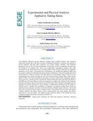
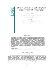
The waves which are produced from deep pile foundations <strong>in</strong> the ground are elastic waves and they are <strong>in</strong><br />
the form <strong>of</strong> shear waves, <strong>com</strong>pression waves and surface waves (Figure1) (Attewell and Farmer, 1973)<br />
Vertically polarized shear waves are generated by soil-shaft contact which propagates radially from the shaft<br />
on a cyl<strong>in</strong>drical surface; meanwhile, <strong>com</strong>pression and shear waves propagate radially <strong>in</strong> all directions from the<br />
toe on a spherical wave front especially at the pile toe, and Rayleigh waves propagate radially on a cyl<strong>in</strong>drical<br />
wave front along the surface. In elastic half space, both Rayleigh and body waves decrease <strong>in</strong> amplitude by<br />
<strong>in</strong>creas<strong>in</strong>g the distance from the pile foundation because <strong>of</strong> the geometrical damp<strong>in</strong>g.<br />
- 1299 -
Vol. 16 [2011], Bund. Q 1300<br />
Figure 1: Wave propagation <strong>in</strong>duced by deep foundation (Attewell and Farmer, 1973)<br />
Wolf (1994)theoretically presents an equation between attenuation <strong>of</strong> ground vibration <strong>in</strong> the far field and<br />
the distance from vibration source; � �� which r is the distance and n is the geometrical attenuation coefficient.<br />
The latter is equal to 0.5 for surface waves propagat<strong>in</strong>g on a cyl<strong>in</strong>drical wave front and equal to 1 for body<br />
waves propagat<strong>in</strong>g on a spherical wave front <strong>in</strong> the <strong>in</strong>terior <strong>of</strong> the half space and equal to 2 for body waves<br />
propagat<strong>in</strong>g along the surface.<br />
PROBLEM DEFINITION AND ASSUMPTIONS<br />
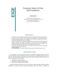
In two-dimensional model the thickness <strong>of</strong> foundation is assumed 1.5m <strong>in</strong> order to be satisfied with the<br />
foundation rigidity under <strong>com</strong>pressive loads and evaluated under assumption <strong>of</strong> isotropic and homogenous with<br />
l<strong>in</strong>ear soil behavior for low deformations.<br />
A rigid concrete (table1) <strong>of</strong> a width <strong>of</strong> 4m (Bf),with 3 piles <strong>of</strong> diameter <strong>of</strong> 70cm and various length (D)<br />
rest<strong>in</strong>g on a soil layer with dynamically and statically different characteristics (table2,3) <strong>of</strong> a limited thickness<br />
underla<strong>in</strong> by a hard stratum at a depth <strong>of</strong> Hm and Length Lm is subjected to a harmonic (f = 50 Hz) <strong>com</strong>pressive<br />
concentrated load P0s<strong>in</strong>(ωt) (Figure 2) an open trench <strong>of</strong> depth H and width w is located at a distance <strong>of</strong> L from<br />
the edge <strong>of</strong> the foundation Table 4)<br />
Table 1: Model concrete properties<br />
Young’s<br />
Modulus<br />
Poisson’s<br />
Ratio<br />
Density Material<br />
Damp<strong>in</strong>g<br />
� � � � � �
Young’s<br />
Modulus<br />
Table 2: Static properties <strong>of</strong> the sandy soils<br />
Poisson’s<br />
Ratio<br />
Specific<br />
Weight<br />
- 1301 -<br />
Density Material<br />
Damp<strong>in</strong>g<br />
Soil’s Mechanical<br />
Parameters<br />
�� � �� � �� � �<br />
Soil<br />
( ��<br />
��) -<br />
( ��<br />
��) (��<br />
��) -<br />
( ��<br />
��) Degree<br />
(1) 30 000 0.35 17.5 1783.89 5% 10 30<br />
(2) 50 000 0.35 19 1936.80 5% 10 40<br />
Dynamical<br />
Properties<br />
Soil<br />
Concret<br />
(<br />
e<br />
�<br />
��) -<br />
( ��<br />
��) -<br />
(1) 2E+10 0.2 2500 2%<br />
Table 3: Dynamic properties <strong>of</strong> the sandy soils<br />
�� Shear<br />
modulus<br />
( ��<br />
� �)<br />
� �<br />
Shear wave<br />
velocity<br />
�<br />
�<br />
K<br />
� � = �.� �<br />
-<br />
� �<br />
Rayleigh wave<br />
velocity<br />
(1) 16000 91 0.936 85<br />
(2) 27000 118 0.936 110<br />
Table 4:Geometric Properties <strong>of</strong> the trench and <strong>Deep</strong> foundation<br />
Explanation Value<br />
Trench Depth 10,15,20,25,30<br />
Pile Length(m) 0,5,10,15,20<br />
Trench Location(m) 20,35,50,70<br />
Trench Width(m) 1<br />
�<br />
�
Vol. 16 [2011], Bund. Q 1302<br />
Hm<br />
Bf<br />
Lm<br />
Figure 2: Problem def<strong>in</strong>ition <strong>of</strong> passive isolation by open trench<br />
GEOMETRIC MODEL<br />
In order to reduce the <strong>com</strong>putation time and <strong>in</strong> accordance with the axisymmetric ½ <strong>of</strong> the actual model is<br />
built <strong>in</strong> two-dimensional model. To prevent any wave reflection from the base <strong>of</strong> model, the depth <strong>of</strong> model is<br />
not less than 30m (Jesmani 2008).<br />
FINITE ELEMENT MODEL STRATEGIES<br />
The properties which affect the wave propagation <strong>in</strong> low stra<strong>in</strong> are Stiffness, Damp<strong>in</strong>g, Poisson, Ratio and<br />
Density. Stiffness and damp<strong>in</strong>g are more important and effective than other properties because the predicted<br />
stra<strong>in</strong>s are lower than 10 -3 ; therefore, l<strong>in</strong>ear elastic is applied to simulate the soil behavior and the above<br />
parameters are <strong>in</strong>volved (Figure 3) ( Ishihara. K, 1996).<br />
In two-dimensional model the <strong>com</strong>putation is done under the assumption <strong>of</strong> pla<strong>in</strong> stra<strong>in</strong> condition. To<br />
simulate the behavior <strong>of</strong> soil <strong>in</strong> places which we have stress concentration and we need exact stra<strong>in</strong>s, two<br />
dimensional PLANE82, In places which the stra<strong>in</strong>s and stresses gradient don’t play an important role <strong>in</strong> results,<br />
two-dimensional PLANE42, and for simulat<strong>in</strong>g the behavior <strong>of</strong> concrete foundation, two-dimensional plane82<br />
have been employed.<br />
To evaluate the behavior <strong>of</strong> soil and the foundation such as slid<strong>in</strong>g or any probable separation at the soil<br />
structure <strong>in</strong>terface, two-dimensional surface-to-surface contact elements (TARGE169, CONTA171) have been<br />
employed. Because <strong>of</strong> the rigidity <strong>of</strong> the foundation <strong>com</strong>pared with the underly<strong>in</strong>g soil, the soil surface and pile<br />
are taken as contact surface and target surface. Normal contact stiffness and maximum contact friction<br />
coefficient are presumed to be equal to 1 and 0.6 respectively. PLANE42 is def<strong>in</strong>ed by four nodes hav<strong>in</strong>g two<br />
degrees <strong>of</strong> freedom at each node and PLANE82 is the developed form <strong>of</strong> PLANE42 with eight<br />
nodes(figure4)and all <strong>of</strong> them have plasticity, creep, swell<strong>in</strong>g, stress stiffen<strong>in</strong>g, large deflection and large stra<strong>in</strong><br />
capabilities (ANSYS Manual).
Figure 3 : Soil behavior models <strong>in</strong> accordance with magnitude <strong>of</strong> stra<strong>in</strong><br />
Figure 4: provided model<strong>in</strong>g elements (L:PLANE42 R:PLANE82)<br />
MESHING AND BOUNDARY CONDITION<br />
The mesh dimension <strong>of</strong> 0.25 times <strong>of</strong> the shortest Rayleigh waves length have been taken with load<strong>in</strong>g<br />
frequency equal to 50 Hz near the foundation and 1.5 times <strong>of</strong> the longest Rayleigh waves length have been<br />
taken with load<strong>in</strong>g frequency equal to 2Hz ( 1� 35<br />
Rayleigh wave length) for other elements.<br />
For distant elements from the trench outer edge, the element size <strong>in</strong>crease gradually.<br />
Boundary conditions are def<strong>in</strong>ed to be restra<strong>in</strong>ed <strong>in</strong> the X and Y direction. The hard stratum underly<strong>in</strong>g the<br />
soil layer has been def<strong>in</strong>ed to be a rigid boundary. Mesh<strong>in</strong>g method is shown <strong>in</strong> Figure 5.<br />
- 1303 -
Vol. 166<br />
[2011], Bund. B Q<br />
Figure F 5: Thhe<br />
geometry <strong>of</strong> the f<strong>in</strong>itee<br />
element moodel<br />
used<br />
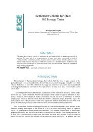
To <strong>in</strong>vesttigate<br />
the val lidity <strong>of</strong> the oobta<strong>in</strong>ed<br />
resuults<br />
from the current studyy<br />
we <strong>com</strong>parre<br />
our results with the<br />
mmodel<br />
which Beskos et al.<br />
(1986) has ddef<strong>in</strong>ed<br />
underr<br />
the assumpttion<br />
<strong>of</strong> pla<strong>in</strong> sstra<strong>in</strong><br />
<strong>in</strong> two-ddimensional<br />
mmodel<br />
by<br />
uus<strong>in</strong>g<br />
BEM aand<br />
also the researches r whhich<br />
Al-Hassaa<strong>in</strong>i<br />
(1991) annd<br />
M. Heshaam<br />
El Naggarr<br />
(2005) havee<br />
done by<br />
uus<strong>in</strong>g<br />
ANSYSS<br />
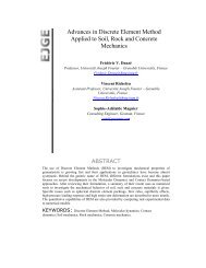
s<strong>of</strong>tware (v version 5.7). Figure (6) exxhibits<br />
an agreeement<br />
betweeen<br />
the currennt<br />
FEM modeel<br />
and the<br />
aabove<br />
researcches.<br />
2.2<br />
2.0<br />
1.8<br />
1.6<br />
1.4<br />
1.2<br />
1.0<br />
0.8<br />
0.6<br />
0.4<br />
0.2<br />
0 0.5 1.0<br />
1.5 2.0 2.5<br />
MODEL<br />
VVERIFICCATION<br />
3.0 3.5 4.0<br />
4.5 5.0 5.5 66.0<br />
6.5 7.0 7. 5 8.0 8.5 9.0<br />
Figure 6: <strong>com</strong>parative<br />
ddiagram<br />
Presennt<br />
stady<br />
Naggaar<br />
2004<br />
Ahmadd<br />
1991<br />
Beskos<br />
1986<br />
9.5 10.0<br />
1304
The vertical and horizontal axes illustrate the Arr (Woods 1968-1969) and trench location normalized by<br />
Rayleigh wave length respectively.<br />
RESULTS FROM THE FINITE ELEMENT ANALYSIS<br />
Woods (1986-1969) put forward Arr which is a ratio <strong>of</strong> amplitude with trench to amplitude without trench<br />
for assess<strong>in</strong>g trench effectiveness.<br />
Arr=<br />
��������� ���� ��� ������ �������<br />
��������� ������� ��� ������ �������<br />
To assess the screen<strong>in</strong>g effectiveness <strong>of</strong> trench, parameter Aarr which is the average <strong>of</strong> amplitude reduction<br />
ratio is employed and it’s calculated along all radial l<strong>in</strong>es near the trench and <strong>in</strong> the length <strong>of</strong> one Rayleigh wave<br />
length.<br />
where,<br />
Aarr= �<br />
�<br />
�<br />
���<br />
∑ Arr<br />
i= is the radial distance between the outer edge <strong>of</strong> the foundation and trench.<br />
n= is the number <strong>of</strong> studied po<strong>in</strong>ts along the radial distances.<br />
The curves which illustrate the changes <strong>of</strong> Aarr aga<strong>in</strong>st the trench location are normalized by trench depth.<br />
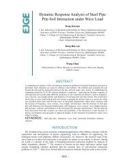
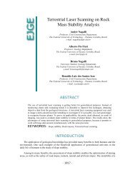
EFFECT OF TRENCH DEPTH<br />
The effect <strong>of</strong> trench depth has been illustrated <strong>in</strong> figures7 through 12.These figures illustrate:<br />
- Increas<strong>in</strong>g the depth <strong>of</strong> trench <strong>in</strong> passive screen<strong>in</strong>g, cause a decrease <strong>in</strong> Arr and this is a tangible behavior<br />
that is reported <strong>in</strong> many published researches.<br />
- In <strong>com</strong>parison to these figures it’s observed that by <strong>in</strong>creas<strong>in</strong>g the length <strong>of</strong> the piles, the diagrams flush<br />
with each other and show that by <strong>in</strong>creas<strong>in</strong>g the length <strong>of</strong> the piles, the distance between trench and vibration<br />
source can be avoided.<br />
- In a constant depth <strong>of</strong> trench, <strong>in</strong> all figures by <strong>in</strong>creas<strong>in</strong>g the quantity <strong>of</strong> L, Arr <strong>in</strong>creases, and the optimal L<br />
is near to 50m which is 0.08 Bf and by go<strong>in</strong>g far from this value (L=0.08 Bf) the trench will be useless.<br />
- 1305 -<br />
i
Vol. 16 [2011], Bund. Q 1306<br />
Average amplitude reduction ratio<br />
1.00<br />
0.90<br />
0.80<br />
0.70<br />
0.60<br />
0.50<br />
0.40<br />
0.30<br />
0.20<br />
0.10<br />
Pile's length (D) =0 m<br />
0.00<br />
0 5 10 15 20 25 30 35<br />
Depth <strong>of</strong> trench (m)<br />
D=0 ,L=20 D=0 ,L=35 D=0 ,L=50 D=0 ,L=70<br />
Poly. (D=0 ,L=20) Poly. (D=0 ,L=35) Poly. (D=0 ,L=50) Poly. (D=0 ,L=70)<br />
Figure 7: Effect <strong>of</strong> trench depth (D=0, Load<strong>in</strong>g frequency=50Hz,Soil 1)<br />
Average amplitude reduction ratio<br />
1.00<br />
0.90<br />
0.80<br />
0.70<br />
0.60<br />
0.50<br />
0.40<br />
0.30<br />
0.20<br />
0.10<br />
Pile's length (D) =10 m<br />
0.00<br />
0 5 10 15 20 25 30 35<br />
Depth <strong>of</strong> trench (m)<br />
D=10 ,L=20 D=10 ,L=35 D=10 ,L=50 D=10 ,L=70<br />
Poly. (D=10 ,L=20) Poly. (D=10 ,L=35) Poly. (D=10 ,L=50) Poly. (D=10 ,L=70)<br />
Figure 8: Effect <strong>of</strong> trench depth (D=10, Load<strong>in</strong>g frequency=50Hz,Soil 1)
Average amplitude reduction ratio<br />
1.00<br />
0.90<br />
0.80<br />
0.70<br />
0.60<br />
0.50<br />
0.40<br />
0.30<br />
0.20<br />
0.10<br />
Pile's length (D) =15 m<br />
0.00<br />
0 5 10 15 20 25 30 35<br />
Depth <strong>of</strong> trench (m)<br />
Figure 9: Effect <strong>of</strong> trench depth (D=15, Load<strong>in</strong>g frequency=50Hz,Soil 1)<br />
Average amplitude reduction ratio<br />
D=15 ,L=20 D=15 ,L=35 D=15 ,L=50 D=15 ,L=70<br />
Poly. (D=15 ,L=20) Poly. (D=15 ,L=35) Poly. (D=15 ,L=50) Poly. (D=15 ,L=70)<br />
1.00<br />
0.90<br />
0.80<br />
0.70<br />
0.60<br />
0.50<br />
0.40<br />
0.30<br />
0.20<br />
0.10<br />
Pile's length (D) =0 m<br />
0.00<br />
0 5 10 15 20 25 30 35<br />
Depth <strong>of</strong> trench (m)<br />
D=0 ,L=20 D=0 ,L=35 D=0 ,L=50 D=0 ,L=70<br />
Poly. (D=0 ,L=20) Poly. (D=0 ,L=35) Poly. (D=0 ,L=50) Poly. (D=0 ,L=70)<br />
Figure 10: Effect <strong>of</strong> trench depth (D=0, Load<strong>in</strong>g frequency=50Hz, Soil 2)<br />
- 1307 -
Vol. 16 [2011], Bund. Q 1308<br />
Average amplitude reduction ratio<br />
1.00<br />
0.90<br />
0.80<br />
0.70<br />
0.60<br />
0.50<br />
0.40<br />
0.30<br />
0.20<br />
0.10<br />
Pile's length (D) =10 m<br />
0.00<br />
0 5 10 15 20 25 30 35<br />
Figure 11: Effect <strong>of</strong> trench depth (D=10, Load<strong>in</strong>g frequency=50Hz, Soil2)<br />
Average amplitude reduction ratio<br />
Depth <strong>of</strong> trench (m)<br />
D=10 ,L=20 D=10 ,L=35 D=10 ,L=50 D=10 ,L=70<br />
Poly. (D=10 ,L=20) Poly. (D=10 ,L=35) Poly. (D=10 ,L=50) Poly. (D=10 ,L=70)<br />
1.20<br />
1.00<br />
0.80<br />
0.60<br />
0.40<br />
0.20<br />
Pile's length (D) =15 m<br />
0.00<br />
0 5 10 15 20 25 30 35<br />
Depth <strong>of</strong> trench (m)<br />
D=15 ,L=20 D=15 ,L=35 D=15 ,L=50 D=15 ,L=70<br />
Poly. (D=15 ,L=20) Poly. (D=15 ,L=35) Poly. (D=15 ,L=50) Poly. (D=15 ,L=70)<br />
Figure 12: Effect <strong>of</strong> trench depth (D=15, Load<strong>in</strong>g frequency=50Hz, Soil2)<br />
EFFECT OF TRENCH LOCATION<br />
As can be seen <strong>in</strong> figures13 through 18, when the depth <strong>of</strong> the trench is approximately near the pile length<br />
(D=10), there is a m<strong>in</strong>imum Aarr with<strong>in</strong> the boundary <strong>of</strong> 4-6 normalized trench location ( �� �<br />
), and by<br />
<strong>in</strong>creas<strong>in</strong>g the depth <strong>of</strong> the trench <strong>in</strong>to 20m and 25m the m<strong>in</strong>imum Aarr takes place with<strong>in</strong> the boundary <strong>of</strong> 2-3<br />
and 0.5-1.5 normalized trench location ( �� �<br />
) respectively. Hence, by <strong>in</strong>creas<strong>in</strong>g the depth <strong>of</strong> the trench related<br />
to the pile length, Aarr decreases by decreas<strong>in</strong>g the distance between foundation and trench (L) Thus, for
passive screen<strong>in</strong>g <strong>in</strong> the case <strong>of</strong> H≈D the trench location 4< �� �<br />
Vol. 16 [2011], Bund. Q 1310<br />
Average amplitude reduction<br />
ratio<br />
0.64<br />
0.63<br />
0.62<br />
0.61<br />
0.60<br />
0.59<br />
0.58<br />
0.57<br />
Depth <strong>of</strong> trench= 25 (m)<br />
0.56<br />
0.00 0.50 1.00 1.50 2.00 2.50 3.00<br />
Normalized trench location (L/H)<br />
D=0 ,H=25 D=5 ,H=25 D=10 ,H=25 D=15 ,H=25<br />
Poly. (D=0 ,H=25) Poly. (D=5 ,H=25) Poly. (D=10 ,H=25) Poly. (D=15 ,H=25)<br />
Figure 15: Effect <strong>of</strong> trench Location (H=25, Load<strong>in</strong>g frequency=50Hz, Soil 1)<br />
Average amplitude reduction<br />
ratio<br />
1.20<br />
1.00<br />
0.80<br />
0.60<br />
0.40<br />
0.20<br />
Depth <strong>of</strong> trench= 10 (m)<br />
0.00<br />
0.00 1.00 2.00 3.00 4.00 5.00 6.00 7.00 8.00<br />
Normalized trench location (L/H)<br />
D=0 ,H=10 D=5 ,H=10 D=10 ,H=10 D=15 ,H=10<br />
Poly. (D=0 ,H=10) Poly. (D=5 ,H=10) Poly. (D=10 ,H=10) Poly. (D=15 ,H=10)<br />
Figure 16: Effect <strong>of</strong> trench Location (H=10, Load<strong>in</strong>g frequency=50Hz, Soil 2)
Average amplitude reduction<br />
ratio<br />
Figure 17: Effect <strong>of</strong> trench Location (H=20, Load<strong>in</strong>g frequency=50Hz, Soil 2)<br />
Average amplitude reduction<br />
ratio<br />
0.82<br />
0.80<br />
0.78<br />
0.76<br />
0.74<br />
0.72<br />
0.70<br />
Depth <strong>of</strong> trench= 20 (m)<br />
0.68<br />
0.00 0.50 1.00 1.50 2.00 2.50 3.00 3.50 4.00<br />
Normalized trench location (L/H)<br />
D=0 ,H=20 D=5 ,H=20 D=10 ,H=20 D=15 ,H=20<br />
Poly. (D=0 ,H=20) Poly. (D=5 ,H=20) Poly. (D=10 ,H=20) Poly. (D=15 ,H=20)<br />
0.66<br />
0.65<br />
0.64<br />
0.63<br />
0.62<br />
0.61<br />
0.60<br />
0.59<br />
0.58<br />
Depth <strong>of</strong> trench= 25 (m)<br />
0.57<br />
0.00 0.50 1.00 1.50 2.00 2.50 3.00<br />
Normalized trench location (L/H)<br />
D=0 ,H=25 D=5 ,H=25 D=10 ,H=25 D=15 ,H=25<br />
Poly. (D=0 ,H=25) Poly. (D=5 ,H=25) Poly. (D=10 ,H=25) Poly. (D=15 ,H=25)<br />
Figure 18: Effect <strong>of</strong> trench Location (H=25, Load<strong>in</strong>g frequency=50Hz, Soil 2)<br />
EFFECT OF PILE LENGTH<br />
Figures 19 through 24 illustrate the effect <strong>of</strong> pile length on Arr and as a result it can be reported that:<br />
For pile length D< �� 2<br />
; there is a reduction <strong>in</strong> Aarr and it shows the significant function <strong>of</strong> open trench<br />
screen<strong>in</strong>g.<br />
For the pile length D> �� 2<br />
; A: For the trenches near vibration source (deep foundations), <strong>in</strong>creas<strong>in</strong>g <strong>in</strong> the<br />
pile length could have a significant effect on Aarr decrease.<br />
B: For the farther trenches, <strong>in</strong>creas<strong>in</strong>g <strong>in</strong> pile length could have a significant effect on decreas<strong>in</strong>g the<br />
function <strong>of</strong> trench barriers (<strong>in</strong>crease <strong>in</strong> Aarr) and it can be as the result <strong>of</strong> decreas<strong>in</strong>g <strong>in</strong> wave amplitude far from<br />
the vibration source.<br />
- 1311 -
Vol. 16 [2011], Bund. Q 1312<br />
Average amplitude<br />
reduction ratio<br />
0.96<br />
0.94<br />
0.92<br />
0.90<br />
0.88<br />
0.86<br />
Depth <strong>of</strong> trench =10 (m)<br />
0.84<br />
0 5 10 15 20<br />
Pile Length (m)<br />
L=20 L=35 L=50 L=70<br />
L<strong>in</strong>ear (L=20) L<strong>in</strong>ear (L=35) L<strong>in</strong>ear (L=50) L<strong>in</strong>ear (L=70)<br />
Figure 19: Effect <strong>of</strong> pile length (H=10, Load<strong>in</strong>g frequency=50Hz, Soil 1)<br />
Average amplitude<br />
reduction ratio<br />
0.88<br />
0.86<br />
0.84<br />
0.82<br />
0.80<br />
0.78<br />
Depth <strong>of</strong> trench =15 (m)<br />
0.76<br />
0 5 10 15 20<br />
Pile Length (m)<br />
L=20 L=35 L=50 L=70<br />
L<strong>in</strong>ear (L=20) L<strong>in</strong>ear (L=35) L<strong>in</strong>ear (L=50) L<strong>in</strong>ear (L=70)<br />
Figure 20: Effect <strong>of</strong> pile length (H=15, Load<strong>in</strong>g frequency=50Hz, Soil 1)
Average amplitude<br />
reduction ratio<br />
0.80<br />
0.78<br />
0.76<br />
0.74<br />
0.72<br />
0.70<br />
Depth <strong>of</strong> trench =20 (m)<br />
0.68<br />
0 5 10 15 20<br />
Pile Length (m)<br />
Figure 21: Effect <strong>of</strong> pile length (H=20, Load<strong>in</strong>g frequency=50Hz, Soil 1)<br />
Average amplitude<br />
reduction ratio<br />
1.20<br />
1.00<br />
0.80<br />
0.60<br />
0.40<br />
0.20<br />
L=20 L=35 L=50 L=70<br />
L<strong>in</strong>ear (L=20) L<strong>in</strong>ear (L=35) L<strong>in</strong>ear (L=50) L<strong>in</strong>ear (L=70)<br />
Depth <strong>of</strong> trench =10 (m)<br />
0.00<br />
0 5 10 15 20<br />
Pile Length (m)<br />
L=20 L=35 L=50 L=70<br />
L<strong>in</strong>ear (L=20) L<strong>in</strong>ear (L=35) L<strong>in</strong>ear (L=50) L<strong>in</strong>ear (L=70)<br />
Figure 22: Effect <strong>of</strong> pile length (H=10, Load<strong>in</strong>g frequency=50Hz, Soil 2)<br />
- 1313 -
Vol. 16 [2011], Bund. Q 1314<br />
Average amplitude<br />
reduction ratio<br />
Figure 23: Effect <strong>of</strong> pile length (H=15, Load<strong>in</strong>g frequency=50Hz, Soil 2)<br />
Average amplitude<br />
reduction ratio<br />
Depth <strong>of</strong> trench =15 (m)<br />
0.92<br />
0.90<br />
0.88<br />
0.86<br />
0.84<br />
0.82<br />
0.80<br />
0.78<br />
0.76<br />
0 5 10 15 20<br />
Pile Length (m)<br />
L=20 L=35 L=50 L=70<br />
L<strong>in</strong>ear (L=20) L<strong>in</strong>ear (L=35) L<strong>in</strong>ear (L=50) L<strong>in</strong>ear (L=70)<br />
0.82<br />
0.80<br />
0.78<br />
0.76<br />
0.74<br />
0.72<br />
0.70<br />
Depth <strong>of</strong> trench =20 (m)<br />
0.68<br />
0 5 10 15 20<br />
Pile Length (m)<br />
L=20 L=35 L=50 L=70<br />
L<strong>in</strong>ear (L=20) L<strong>in</strong>ear (L=35) L<strong>in</strong>ear (L=50) L<strong>in</strong>ear (L=70)<br />
Figure 24: Effect <strong>of</strong> pile length (H=20, Load<strong>in</strong>g frequency=50Hz, Soil 2)<br />
EFFECT OF SOIL PROPERTIES<br />
Figure 25 shows that <strong>in</strong>creas<strong>in</strong>g the Young's modulus lead to an <strong>in</strong>crease <strong>in</strong> Aarr and the steep <strong>of</strong> this<br />
<strong>in</strong>crease <strong>in</strong> relation with Aarr <strong>in</strong>crease is about 5 percent. This <strong>in</strong>crease <strong>in</strong> stiff soils can be focused on as the<br />
result <strong>of</strong> damp<strong>in</strong>g decrease and also as the result <strong>of</strong> wave velocity <strong>in</strong>crease which leads to an <strong>in</strong>crease <strong>in</strong> Raleigh<br />
wave length.
Average amplitude<br />
reduction factor<br />
0.48<br />
0.47<br />
0.46<br />
0.45<br />
0.44<br />
0.43<br />
0.42<br />
0.41<br />
0.40<br />
Figure 25: Effect <strong>of</strong> soil properties<br />
EFFECT OF LOADING TIME<br />
Generally, <strong>in</strong> this model <strong>in</strong>creas<strong>in</strong>g the load<strong>in</strong>g time until 1.5s leads to an <strong>in</strong>crease <strong>in</strong> Aarr and upper<br />
amounts <strong>of</strong> load<strong>in</strong>g time don’t have any effects on Aarr, as can be seen <strong>in</strong> figure 26.<br />
Average amplitude reduction<br />
Ratio<br />
0.41<br />
Soil Chart<br />
D10 L50 H30<br />
0 0.5 1 1.5 2 2.5 3 3.5<br />
0.60<br />
0.50<br />
0.40<br />
0.30<br />
0.20<br />
0.10<br />
Soil Number<br />
Figure 26: Effect <strong>of</strong> load<strong>in</strong>g time<br />
CONCLUSIONS<br />
In this research, a two-dimensional f<strong>in</strong>ite element analysis has been conducted to evaluate the effects <strong>of</strong><br />
passive open-trench screen<strong>in</strong>g system on decreas<strong>in</strong>g the amplitude <strong>of</strong> Rayleigh waves by employ<strong>in</strong>g ANSYS<br />
<strong>com</strong>puter program and the follow<strong>in</strong>g conclusions could be distilled:<br />
- 1315 -<br />
0.45<br />
E=30 Mpa ,φ=30˚ E=40 Mpa ,φ=35˚ E=50 Mpa ,φ=40˚<br />
D=10,L=50,H=30,Frequency=5Hz<br />
0.00<br />
0 1 2 3 4 5 6<br />
Time( Second )<br />
D=10,L=50,H=30,Frequency=5Hz<br />
0.48
Vol. 16 [2011], Bund. Q 1316<br />
By determ<strong>in</strong><strong>in</strong>g an optimal depth for piles, the distance between trench and vibration source can be avoided.<br />
The optimal distance for L is 0.08 Bf and by go<strong>in</strong>g far from this value (L=0.08 Bf) the trench will be useless.<br />
For passive screen<strong>in</strong>g <strong>in</strong> the case <strong>of</strong> H≈D the trench location 4< �� �<br />
�� 2<br />
pile length variations could have an important effect on the open trench function.<br />
Open trench screen<strong>in</strong>g with constant depth is more effective <strong>in</strong> collapsible soils than stiff soils and this can<br />
be as the result <strong>of</strong> Rayleigh wavelength reduction <strong>in</strong> collapsible soils.<br />
REFERENCES<br />
1. Aboudi J. (1973) “Elastic waves <strong>in</strong> half-space with th<strong>in</strong> barrier”. J EngMech (ASCE); 99(1):69–83.<br />
2. Ahmad S, Al-Hussa<strong>in</strong>i T.M. “Simplified design for vibration screen<strong>in</strong>g by open and <strong>in</strong> filled trenches”.<br />
Journal <strong>of</strong> Geotechnical Eng<strong>in</strong>eer<strong>in</strong>g. ASCE 1991; 117(1): 67-88.<br />
3. ANSYS User’s manual, ANSYS Inc.,Canonsburg, Pa.<br />
4. Al-Hussa<strong>in</strong>i, T.M. and Ahmad, S. (1991) “Design <strong>of</strong> wave barriers for reduction <strong>of</strong> horizontal ground<br />
vibration”, Journal <strong>of</strong> Geotechnical Eng<strong>in</strong>eer<strong>in</strong>g, ASCE, Vol. 117, No. 4, pp. 616-636.<br />
5. Ahmad S, Al-Hussa<strong>in</strong>i T.M. “Active isolation <strong>of</strong> mach<strong>in</strong>e foundation by <strong>in</strong>-filled Trench barriers”.<br />
Journal <strong>of</strong> Geotechnical Eng<strong>in</strong>eer<strong>in</strong>g. ASCE 1996; 122(4): 288-94.<br />
6. Ahmad S, Al-Hussa<strong>in</strong>i T.M. “An Investigation on active isolation <strong>of</strong> mach<strong>in</strong>e foundation by open<br />
trench”. Journal <strong>of</strong> Geotechnical Eng<strong>in</strong>eer<strong>in</strong>g. ASCE 1996; 122(6): 454-61.<br />
7. Amick H and Gendreau M (2000) “Construction Vibrations and Their Impact on Vibration-Sensitive<br />
Facilities”. , ASCE Construction Congress 6 Orlando, Florida, February 22, 2000.<br />
8. Al-Hussa<strong>in</strong>i T.M, and Ahmad, S. (2000) “Numerical and experimental studies on vibration screen<strong>in</strong>g by<br />
open and <strong>in</strong>-filled trench barriers”. International Workshop on Wave Propagation, Mov<strong>in</strong>g Load and<br />
Vibration Reduction, (WAVE2000) Rotterdam: Balkema , 241–250.<br />
9. Adam M, Estorff.O (2005) “Reduction <strong>of</strong> tra<strong>in</strong>-<strong>in</strong>duced build<strong>in</strong>g vibrations by us<strong>in</strong>g open and filled<br />
trenches”. Computers and Structures, 83, 11–24.<br />
10. Adam M, Estorff.O (2005) “Reduction <strong>of</strong> tra<strong>in</strong>-<strong>in</strong>duced build<strong>in</strong>g vibrations by us<strong>in</strong>g open and filled<br />
trenches”. Computers and Structures, 83, 11–24.<br />
11. Bornitz G. Uber die Ausberit<strong>in</strong>g der von Groszkolbenmasch<strong>in</strong>enerzengtenBondenschw<strong>in</strong>gungen <strong>in</strong> die<br />
Tiefe . Berl<strong>in</strong>: 1931.<br />
12. Barkan, D. D. (1962) “Dynamics <strong>of</strong> Bases and Foundation”. McGraw-Hill, New York.<br />
13. Beskos, D., Dasgupta, G., and Vardoulakis, I.G. 1985. “Vibration isolation <strong>of</strong> mach<strong>in</strong>e foundations.” In<br />
Vibration problems <strong>in</strong> geotechnical eng<strong>in</strong>eer<strong>in</strong>g. ASCE, NY. 138–151.<br />
14. Beskos, D.E., Dasgupta, G., and Vardoulakis, I.G. (1986a) “Vibration isolation us<strong>in</strong>g open or filled<br />
trenches, Part 1: 2-D homogeneous soil.” Computational Mechanics, 1(1), 43–63.
15. Beskos, D., Leung, K, Vardoulakis, I.G. (1986) “Vibration isolation <strong>of</strong> structures from surface waves <strong>in</strong><br />
layered soil”. In Recent applications <strong>in</strong> <strong>com</strong>putational mechanics. ASCE, NY. 125–140.<br />
16. Beskos, D.E., Leung, K.L., and Vardoulakis, I.G. (1990) “Vibration isolation us<strong>in</strong>g open or filled<br />
trenches, Part 3: 2-D non-homogeneous soil”. Computational Mechanics, 7(1), 137–148.<br />
17. Beskos, D.E., Leung, K.L., and Vardoulakis, I.G. (1991) “Vibration isolation by trenches <strong>in</strong><br />
cont<strong>in</strong>uously nonhomogeneous soil by the BEM.” Soil Dynamics and Earthquake Engrg., 10(3), 172–<br />
179.<br />
18. Cook,R.D., Malkus,D.S., and Plesha,M.E.,”Concepts and Applications <strong>of</strong> F<strong>in</strong>ite Element Analysis 3D<br />
ed”.,John Wiley and sons,New York,1989.<br />
19. Celebi E., Fırat S., Cankayac I. (2006) “The effectiveness <strong>of</strong> wave barriers on the dynamic stiffness<br />
coefficients <strong>of</strong> foundations us<strong>in</strong>g boundary element method”. Applied Mathematics and Computation<br />
doi: 10.1016/ j.amc. 2006 .01.008.<br />
20. Celebi, E. (2006) “Three-dimensional modell<strong>in</strong>g <strong>of</strong> tra<strong>in</strong>-track and sub-soil analysis for surface<br />
vibrations due to mov<strong>in</strong>g loads.” Applied Mathematics and Computation, 1-22.<br />
21. Das B.M. Pr<strong>in</strong>ciples <strong>of</strong> soil dynamics.USA: PWS-KENT, 1993: 243.<br />
22. Edriss ,I.M ,and Bolton Seed ,(1974) “Seismic response by variable damp<strong>in</strong>g f<strong>in</strong>ite elements.’’J.Geo.<br />
Eng. ASCE, 100(1),1-13.<br />
23. El Naggar, M.H., Chehab, A.G. (2005) “Vibration barriers for shock-produc<strong>in</strong>g equipment”. Can.<br />
Geotech. J. 42: 297–306.<br />
24. Fuykui M, Matsumoto Y.,(1980) “F<strong>in</strong>ite difference analysis <strong>of</strong> Rayleigh wave scatter<strong>in</strong>g at a trench.”<br />
Bull SeismolSocAmer 1980; 70(6):2051–69.<br />
25. G. Segol, P. C. Y. Lee and J. F. Abel (1978) “Amplitude reduction <strong>of</strong> surface waves by trenches”, J.<br />
eng.mech, div. ASCE 104,621441 (1978)<br />
26. Gao, G.Y, Li, Z.Y, Qiu, CH. ,Yue, Z.Q., “ Three dimensional analysis <strong>of</strong> piles as passive barriers for<br />
ground vibration isolation”. Soil Dynamics and earthquake eng. 26 (2006): pp.1015-1027.<br />
27. Haupt WA. (1977) “<strong>Isolation</strong> <strong>of</strong> vibrations by concrete core walls.” In: Proceed<strong>in</strong>gs <strong>of</strong> the n<strong>in</strong>th<br />
<strong>in</strong>ternational conference on soil mechanics and foundation eng<strong>in</strong>eer<strong>in</strong>g, vol. 2. Tokyo, Japan, 1 p. 251–6.<br />
28. Haupt (1977) “Surface waves <strong>in</strong> no homogeneous half space”, Proc. DMSR77 Karlsruhe 1, 355-367.<br />
29. Hirokazu Takemiya ,Xue Cheng Bian (2006) “Sh<strong>in</strong>kansen high-speed tra<strong>in</strong> <strong>in</strong>duced ground vibration <strong>in</strong><br />
view <strong>of</strong> viaduct-ground <strong>in</strong>teraction” Soil Dynamic and Earthquake Eng<strong>in</strong>eer<strong>in</strong>g 27(2006)506-520.<br />
30. Ishihara, k.(1996) “Soil behavior <strong>in</strong> earthquake geotechnics.” USA by Oxford University, Press Inc,<br />
NewYork.<br />
31. Jesmani et.al (2008) "F<strong>in</strong>ite Element Analysis <strong>of</strong> Active <strong>Isolation</strong> <strong>of</strong> <strong>Deep</strong> Foundation <strong>in</strong> Clayey Soil by<br />
Rectangular Trenches". Vol. 13, Bund. E, 1-16.<br />
32. Kattis, S.E., Polyzos, D., and Beskos, D.E. (1999a) “Modell<strong>in</strong>g <strong>of</strong> pile barriers by effective trenches and<br />
their screen<strong>in</strong>g effectiveness”. Soil Dynamics and Earthquake Engrg, 18(1), 1–10.<br />
33. Kattis, S.E., Polyzos, D., and Beskos, D.E. (1999b) “Vibration isolation by a row <strong>of</strong> piles us<strong>in</strong>g a 3-D<br />
frequency doma<strong>in</strong> BEM.” International J. for Numerical Methods <strong>in</strong> Engrg, 46: 713–728.<br />
34. Karlstrom, A., A. Bostrom, “Efficiency <strong>of</strong> trenches along railways for tra<strong>in</strong>s mov<strong>in</strong>g at sub or<br />
supersonic speeds”, Soil Dynamics and Earthquake Eng<strong>in</strong>eer<strong>in</strong>g, 27 (2007): 625–641.<br />
35. Lamb, H.(1904) “On the Propagation <strong>of</strong> Tremors over the Surface <strong>of</strong> an Elastic Solid”, Philos.<br />
Trans.R.S. London, Ser .A, Vol.203, pp1-42.<br />
- 1317 -
Vol. 16 [2011], Bund. Q 1318<br />
36. Liao,S; Sangrey, D.A.(1978): “ Use <strong>of</strong> piles as isolation barriers”. Proc. ASCE 104, J.Geotech. Engng.<br />
Dir., GT9, 1139-1152.<br />
37. K.L. Leung and I.G. Vardoulakis, D.E. Beskos , J.L. Tassoulas. “Vibration isolation by trenches <strong>in</strong><br />
cont<strong>in</strong>uously no homogeneous soil by BEM”. Soil dynamics and earthquake Eng. 1991, Vol.10<br />
(3):pp172-178.<br />
38. May, T.W., and Bolt, B.A. (1982) “The effectiveness <strong>of</strong> trenches <strong>in</strong> reduc<strong>in</strong>g seismic motion”.<br />
Earthquake Engrg. And Structural Dynamics, 10(2), 195–210.<br />
39. Novak, M., and Mitwally, H. 1988. “Transmitt<strong>in</strong>g boundary for axisymmetric dilation problems”.<br />
Journal <strong>of</strong> Eng<strong>in</strong>eer<strong>in</strong>g Mechanics, ASCE, 114(1): 181–187.<br />
40. R.Paolucci,A.Maffeis,L.Scandella,M.Sttupazz<strong>in</strong>i,M.Van<strong>in</strong>i”Numerical Prediction <strong>of</strong> low-frequency<br />
ground vibrations <strong>in</strong>duced by high-speed tra<strong>in</strong> at Ledsgaard,Sweden” Soil Dynamic and Earthquake<br />
Eng<strong>in</strong>eer<strong>in</strong>g 23(2003)425-433<br />
41. Shen-Haw Jo, Hung-Ta L<strong>in</strong>, “Analysis <strong>of</strong> tra<strong>in</strong>-<strong>in</strong>duced vibrations and vibration reduction schemes<br />
above and below critical Rayleigh speeds by f<strong>in</strong>ite element method”., Soil Dynamics and earthquake<br />
Eng, 24 (2004); pp.993-1002.<br />
42. Tsai Pei-hsun a, Zheng-yiFengb,T<strong>in</strong>-lon Jen, “Three-dimensional analysis <strong>of</strong> the screen<strong>in</strong>g effectiveness<br />
<strong>of</strong> hollow pile barriers for foundation-<strong>in</strong>duced vertical vibration” ,Comput Geotech(2007) , doi:10.1016/<br />
j.<strong>com</strong>pgeo. 2007.05.010<br />
43. Woods, R.D. (1967) “Screen<strong>in</strong>g <strong>of</strong> surface waves by trenches”. PhD dissertation. Univ. Of Michigan,<br />
Ann Arbor. Mich.<br />
44. Woods, R.D. (1968) “Screen<strong>in</strong>g <strong>of</strong> surface waves <strong>in</strong> soils”, Journal <strong>of</strong> Soil Mechanics and <strong>Foundations</strong><br />
Division, ASCE, Vol. 94, No. 4, pp. 951-979.<br />
45. Woods, R.D. (1968) “Screen<strong>in</strong>g <strong>of</strong> surface waves <strong>in</strong> soils”, Journal <strong>of</strong> Soil Mechanics and <strong>Foundations</strong><br />
Division, ASCE, Vol. 94, No. 4, pp. 951-979.<br />
46. Woods R.D. “Vibration <strong>of</strong> soils and foundation”. New Jersy: Prentice-Hall, 1970.<br />
47. Wass, G. (1972) “L<strong>in</strong>ear two-dimentional analysis <strong>of</strong> soil dynamics problems <strong>in</strong> semi-<strong>in</strong>f<strong>in</strong>ite layered<br />
media.” PhD. Thesis, University <strong>of</strong> California at Berkley, Calif.<br />
48. Wood S., 1991. Performance <strong>of</strong> RC build<strong>in</strong>gs dur<strong>in</strong>g the 1985 Chile earthq.: “ implications for the<br />
design <strong>of</strong> structural walls ” Earthquake Spectra, 7(4), 607-638.<br />
49. Wolf JP. (1994), “Foundation vibration analysis us<strong>in</strong>g simple physical models”. Englewood Cliffs, NJ:<br />
Prentice-Hall.<br />
50. Yeh, C.S., Liao, W.I., Tsai, J.F. and Teng, T.J. (1997) “Tra<strong>in</strong> <strong>in</strong>duced Ground motion and its mitigation<br />
by trench and WIB”, (<strong>in</strong> Ch<strong>in</strong>ese) Report <strong>of</strong> NCREE-97-009, NAT. Center for Research on earthquake<br />
Engng., Taipei, Taiwan, R.O.C.<br />
© 2011 ejge