Type 4300 Catalogue - GMM Pfaudler Ltd
Type 4300 Catalogue - GMM Pfaudler Ltd
Type 4300 Catalogue - GMM Pfaudler Ltd

Create successful ePaper yourself
Turn your PDF publications into a flip-book with our unique Google optimized e-Paper software.
o<br />
Product Temperature ( C)<br />
o<br />
Jacket Fluid Temperature ( C)<br />
<br />
250<br />
200<br />
150<br />
100<br />
50<br />
0<br />
-50<br />
-100<br />
-100 -50 0 50 100 150 200 250<br />
<br />
400<br />
300<br />
200<br />
100<br />
0<br />
o<br />
Wall Temperature ( C)<br />
o<br />
ASME Code limits low temp. to -30 C<br />
<br />
-100<br />
-100 -50 0 50 100 150 200 250<br />
o<br />
Wall Temperature ( C)<br />
o<br />
ASME Code limits low temp. to -30 C<br />
Steam<br />
Hot Oil,<br />
2<br />
1500 W/m K<br />
Hot Oil,<br />
2<br />
1000 W/m K<br />
Heating<br />
<br />
<br />
<br />
<br />
<br />
<br />
<br />
<br />
Cooling<br />
Heating<br />
<br />
Cooling<br />
<br />
<br />
<br />
<br />
<br />
<br />
<br />
<br />
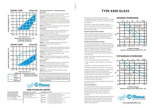
Exercise No. 1<br />
Determine the maximum and minimum allowable wall temperatures of a<br />
0<br />
vessel when introducing a product at 100 C into the vessel.<br />
Procedure: Since the media is being introduced into the vessel, Chart A<br />
0<br />
applies. Find the product temperature of 100 C on the product<br />
temperature axis (ordinate). If you follow this constant temperature along<br />
the wall temperature axis (abscissa), you will see it intersects the polygon<br />
0 0<br />
at wall temperatures of -30 C at the lower temperature end and at 232 C<br />
at the upper temperature end.<br />
0<br />
Answer: Product at 100 C can safely be introduced into a vessel whose<br />
0<br />
wall temperature is between -30 and 232 C.<br />
Exercise No. 2<br />
0<br />
A vessel with a wall temperature of 100 C is to be heated using hot oil<br />
2<br />
with a heat transfer film coefficient of 1500 W/m K. What is the<br />
maximum temperature oil that can be used?<br />
Procedure: Since the media is being introduced into the jacket, Chart B<br />
0<br />
applies. Find the wall temperature of 100 C along the wall temperature<br />
axis (abscissa). If you follow this line along the jacket temperature axis<br />
2<br />
(ordinate), it intersects the oil (1500 W/m K) polygon at a jacket<br />
0<br />
temperature of 257 C.<br />
2<br />
Answer: The maximum allowable temperature of a 1500 W/m K oil<br />
0 0<br />
introduced into the jacket of a 100 C vessel is 257 C.<br />
Exercise No. 3<br />
A batch has just been completed, and the wall temperature of the vessel<br />
0<br />
is 150 C. What are the upper and lower temperature limits of the product<br />
that can be introduced in the vessel for the next batch?<br />
0<br />
Procedure: Chart A applies. Find the temperature of 150 C on the wall<br />
temperature axis. This line intersects the polygon at product<br />
0<br />
temperatures of -5 and 232 C.<br />
Answer: The maximum and minimum temperatures of a product that<br />
0<br />
can be introduced into a vessel with a wall temperature of 150 C are 232<br />
0<br />
and -5 C respectively.<br />
Exercise No. 4<br />
Steam is being used to heat a product in a vessel. The vessel contents<br />
0 0<br />
are at 125 C. Can 250 C steam be introduced into the jacket?<br />
Procedure: Chart B applies. The intersection of a wall temperature of<br />
0 0<br />
125 C and a jacket temperature of 250 C is outside the steam polygon<br />
on the chart.<br />
0<br />
Answer: Steam at 250 C cannot be introduced safely into a vessel<br />
0<br />
whose contents are at 125 C.<br />
The information contained in this bulletin is believed to be reliable general guidelines<br />
for consideration of the products and services described herein. The information is<br />
general in nature and should not be considered applicable to any specific process or<br />
application. The <strong>Pfaudler</strong> Companies, Inc. expressly disclaim any warranty,<br />
express or implied, of fitness for any specific purpose in connection with the<br />
information contained herein.<br />
<br />
<br />
<br />
<br />
<br />
<br />
<br />
<br />
<br />
<br />
<br />
PE/06-<strong>GMM</strong>-01/05<br />
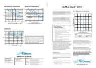
Chemical glasses and glass coatings for chemical apparatii<br />
characteristically have superior acid resistance. This is due to their acidic<br />
components and structure. For this reason, acid resistance is their major<br />
field of application.<br />
Alkali resistance is usually the inherent advantage of metallic and<br />
polymeric vessel materials and defines their principal application range.<br />
However, decades of <strong>Pfaudler</strong> research and development have finally<br />
broken down these boundaries.<br />
<br />
<strong>Pfaudler</strong>’s standard glass coatings already have relatively high alkali<br />
resistance without compromising their extremely high acid resistance.<br />
They are ideal for conventional glass coating applications and are<br />
preferred for highly acid operations with occasional neutralization and<br />
intermediate alkaline operations.<br />
<br />
<strong>Type</strong> <strong>4300</strong> glass coatings represent a new aspect of this tradition and<br />
are designed to bridge a perceived gap in the application range. <strong>Pfaudler</strong><br />
<strong>Type</strong> <strong>4300</strong> glass is still an acidic type of glass, but its primary application<br />
is based on improved alkali resistance. <strong>Pfaudler</strong> <strong>Type</strong> <strong>4300</strong> glass<br />
coatings are advisable wherever alkaline conditions prevail during the<br />
cycle, or as a result of concentration and temperature, or where<br />
concentration and/or temperature conditions exceed permissible limits<br />
for conventional glass.<br />
In addition, <strong>Type</strong> <strong>4300</strong> glass coatings are advisable where any of the<br />
following conditions exist :<br />
• Protection of alkaline products against metal contamination.<br />
• Danger of discoloration of alkaline products due to incorporation of<br />
metals.<br />
• Stabilization of high-molecular alkalis sensitive to metal contact.<br />
• Inadequate redox stability of the vessel material in the alkaline range.<br />
Compared to our world renowned standard glass, <strong>Type</strong> <strong>4300</strong> has three<br />
times better alkali resistance. This means that higher process<br />
temperatures can be used, or that, under otherwise equal conditions,<br />
these glass coatings will have three times the life expectations.<br />
The <strong>Type</strong> <strong>4300</strong> glass does make a slight concession in the area of acid<br />
resistance. Although it is adequate for mild service, it is not<br />
recommended for agressive acid conditions.<br />
The isocorrosion curves and thermal limit diagrams for <strong>Type</strong> <strong>4300</strong> glass<br />
appear in the next section.<br />
<br />
In the charts that follow, we present the isocorrosion curves for <strong>4300</strong><br />
glass. The curves are for pure acids and bases most commonly used in<br />
the chemical industry and take into account technically relevant<br />
parameters influencing the rate of corrosion (for example, the<br />
volume/surface area into, inhibition effects, concentration, and<br />
temperature).<br />
In practical operation these materials are always encountered with liquid<br />
additives, dissolved substances or gases which may have positive or<br />
negative effects on resistance. We therefore recommend performing<br />
corrosion tests or contacting a <strong>Pfaudler</strong> consultant to assure material<br />
suitability for individual processes.<br />
TYPE <strong>4300</strong> GLASS<br />
<br />
<br />
<br />
<br />
<br />
<br />
<br />
<br />
<br />
<br />
<br />
<br />
<br />
<br />
<br />
<br />
<br />
<br />
<br />
<br />
<br />
<br />
<br />
<br />
<br />
<br />
<br />
<br />
<br />
<br />
<br />
www.gmmpfaudler.com
140<br />
10 11<br />
12 pH<br />
140<br />
10 11<br />
12 13 pH<br />
220<br />
120<br />
0.5 mm/year<br />
0.2 mm/year<br />
120<br />
0.5 mm/year<br />
220<br />
180<br />
C<br />
100<br />
80<br />
0.1 mm/year<br />
Fully Resistant<br />
60<br />
0.001 0.01 0.1 0.5 1 5 10<br />
% Na2CO 3 by Weight<br />
Volume to Surface Area Ratio (V/O) = 20<br />
C<br />
100<br />
80<br />
0.2 mm/year<br />
0.1 mm/year<br />
Fully Resistant<br />
60<br />
0.001 0.01 0.05 0.1 0.5 1 5 10 20<br />
% NH by Weight<br />
3<br />
Volume to Surface Area Ratio (V/O) = 20<br />
C<br />
180<br />
140<br />
100<br />
60<br />
0.5 mm/year<br />
0.2 mm/year<br />
0.1 mm/year<br />
Fully Resistant<br />
20 40 60 80 100<br />
C<br />
140<br />
100<br />
60<br />
40<br />
0.5<br />
mm/year<br />
0.1 mm/year<br />
Fully Resistant<br />
0.2<br />
mm/year<br />
20 40 60 80 100<br />
% H SO by Weight<br />
2 4<br />
Volume to Surface Area Ratio (V/O) = 20<br />
% H PO by Weight<br />
3 4<br />
Volume to Surface Area Ratio (V/O) = 20<br />
<br />
<br />
<br />
<br />
C<br />
200<br />
180<br />
160<br />
140<br />
120<br />
100<br />
80<br />
60<br />
10<br />
0.5 mm/year<br />
0.2 mm/year<br />
0.1 mm/year<br />
Fully Resistant<br />
20 30<br />
% HCL by Weight<br />
Volume to Surface Area Ratio (V/O) = 20<br />
C<br />
200<br />
180<br />
160<br />
140<br />
120<br />
100<br />
80<br />
0.5 mm/year<br />
0.2 mm/year<br />
0.1 mm/year<br />
Fully Resistant<br />
20 40<br />
60<br />
% HNO by Weight<br />
3<br />
Volume to Surface Area Ratio (V/O) = 20<br />
C<br />
220<br />
200<br />
180<br />
160<br />
140<br />
120<br />
0.5 mm/year<br />
0.2 mm/year<br />
0.1 mm/year<br />
Fully Resistant<br />
20 40 60 80 100<br />
% CH COOH by Weight<br />
3<br />
Volume to Surface Area Ratio (V/O) = 20<br />
Although <strong>Type</strong> <strong>4300</strong> glass has a high degree of helpful compressive<br />
stress in the glass layer, there are definite limits to the level of thermal<br />
stress which the glass can withstand without incurring damage.<br />
Only two conditions must be considered when determining the<br />
temperature limits:<br />
A. Introduction of media into a vessel. The limits are determined from<br />
Chart A (located on next page).<br />
B. Introduction of media into a jacket. The limits are determined from<br />
Chart B (located on next page).<br />
In both cases the safe operating range lies within the polygons as<br />
outlined on the charts. The left and right sides on the polygons represent,<br />
respectively, the minimum and maximum wall temperatures allowed. The<br />
bottom and top on the polygons represent, respectively, the minimum<br />
and maximum product temperatures allowed (Chart A) and the minimum<br />
and maximum jacket temperatures allowed (Chart B).<br />
With Chart B, it is also necessary to know the heat transfer film<br />
coefficient of the jacket media. Three curves are shown : one for steam<br />
2 2<br />
(8500 Wm K) and two for typical heating oils (1500 and 1000 Wm K).<br />
CAUTION : “Safe” operating temperatures vary with conditions.<br />
Because so many variables are involved, temperature ranges are<br />
given only as a guide. When practical, operation below the<br />
maximum and above the minimum is recommended. Contact<br />
<strong>Pfaudler</strong> for details.