
You also want an ePaper? Increase the reach of your titles
YUMPU automatically turns print PDFs into web optimized ePapers that Google loves.
GL256/7 LOFT LADDER FIXING INSTRUCTIONS<br />
The ladder should not be fitted if the floor to floor height is greater than 2692mm.<br />
DO NOT ATTEMPT TO USE THE LADDER UNTIL STEPS 1 TO 5 BELOW HAVE BEEN COMPLETED.<br />
Contents:<br />
2 section Loft ladder including guide assembly<br />
1 no. Operating Pole<br />
10 no. 8x1” screws<br />
General Specification:<br />
Min. loft opening 560x457mm<br />
Min. loft clearance required 710mm<br />
Min. loft floor clearance required 1270mm<br />
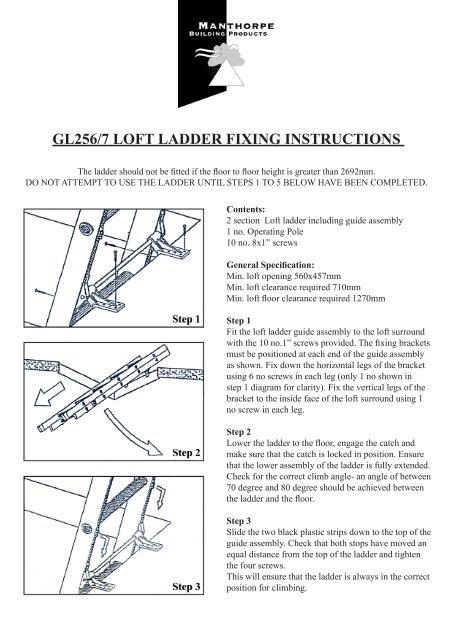
Step 1<br />
Fit the loft ladder guide assembly to the loft surround<br />
with the 10 no.1” screws provided. The fixing brackets<br />
must be positioned at each end of the guide assembly<br />
as shown. Fix down the horizontal legs of the bracket<br />
using 6 no screws in each leg (only 1 no shown in<br />
step 1 diagram for clarity). Fix the vertical legs of the<br />
bracket to the inside face of the loft surround using 1<br />
no screw in each leg.<br />
Step 2<br />
Lower the ladder to the floor, engage the catch and<br />
make sure that the catch is locked in position. Ensure<br />
that the lower assembly of the ladder is fully extended.<br />
Check for the correct climb angle- an angle of between<br />
70 degree and 80 degree should be achieved between<br />
the ladder and the floor.<br />
Step 3<br />
Slide the two black plastic strips down to the top of the<br />
guide assembly. Check that both stops have moved an<br />
equal distance from the top of the ladder and tighten<br />
the four screws.<br />
This will ensure that the ladder is always in the correct<br />
position for climbing.
When installed, the ladder should always be pulled<br />
down against these before extending the bottom section<br />
and ascending. Both feet of the ladder should rest<br />
firmly on the floor.<br />
Step 4<br />
Release the catch and slide the sections together making<br />
sure the catch locks in its closed position and push<br />
the loft ladder fully into the loft.<br />
Slide the two red plastic stops at the bottom of the<br />
ladder up to the underside of the guide assembly and<br />
tighten the four screws. This will ensure that the ladder<br />
clears the trap door when closed.<br />
Step 5<br />
To lower and raise the loft ladder, use the pole provided<br />
by inserting this into a rung hole.<br />
PLEASE LEAVE THE FIXING INSTRUCTION FOR THE OCCUPANTS.<br />
NEVER CLIMB LADDER UNLESS FULLY EXTENDED WITH CATCH ENGAGED AND BOTH<br />
TOP STOPS IN CONTACT WITH GUIDE ASSEMBLY.<br />
ONLY ONE PERSON ON THE LADDER AT ANYTIME.<br />
USE BOTH HANDS WHENEVER POSSIBLE<br />
CHECK SCREWS, RIVETS ETC. AT REGULAR INTERVALS.<br />
MAXIMUMLOAD WEIGHT - 150 KGS MAX.<br />
Manthorpe Building Products Ltd.<br />
Manthorpe House, Brittain Drive, Codnor Gate Business Park, Ripley, Derbyshire, DE5 3ND<br />
t: +44(0)1773 514200 f: +44(0)1773 514262 e: sales@manthorpe.co.uk w: www.manthorpe.co.uk