Pan Matrix Film Processing - David Doubley
Pan Matrix Film Processing - David Doubley
Pan Matrix Film Processing - David Doubley

Create successful ePaper yourself
Turn your PDF publications into a flip-book with our unique Google optimized e-Paper software.
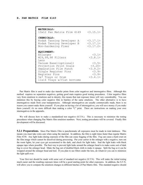
B. PAN MATRIX FILM 4149<br />
╔════════════════════════════════════════╗<br />
║ MATERIALS:<br />
║<br />
║ 10x12 <strong>Pan</strong> <strong>Matrix</strong> <strong>Film</strong> 4149 ║<br />
║<br />
║<br />
║ CHEMICALS:<br />
║<br />
║ Kodak Tanning Developer A ║<br />
║ Kodak Tanning Developer B ║<br />
║ Non-hardening Fixer<br />
║<br />
║<br />
║<br />
║ EQUIPMENT:<br />
║<br />
║ Enlarger<br />
║<br />
║ #29,99,98 Filters<br />
║<br />
║ Lens<br />
║<br />
║ Vacuum Easel(optional)<br />
║<br />
║ Projection Print Scale<br />
║<br />
║ Separation <strong>Film</strong> Punch<br />
║<br />
║ Single Register Pins<br />
║<br />
║ Register Pins<br />
║<br />
║ 5x7 Trays or Drum<br />
║<br />
║ 11x14 Trays w/flat bottoms<br />
║<br />
╚════════════════════════════════════════╝<br />
<strong>Pan</strong> <strong>Matrix</strong> film is used to make dye transfer prints from color negatives and internegative films. Although this<br />
method requires no separation negatives, getting good mats requires good testing procedures. Color negative films<br />
vary from emulsion to emulsion and in density; this means that mat exposure times will vary considerably. You can<br />
minimize this by buying color negative film in batches of the same emulsion. The other alternative is to have<br />
internegatives made from your transparencies. Although internegatives are usually commercially made, there is no<br />
reason you cannot make them yourself. If you plan on having a lot of internegatives, you will save money if you make<br />
them yourself; it's no more difficult than making a color "C" print. There are instructions on making your own<br />
internegatives in the appendix.<br />
We will discuss how to make a standardized test negative (S.T.N.). This is necessary to minimize the testing<br />
procedures when changing <strong>Pan</strong> <strong>Matrix</strong> film emulsion numbers. Next, testing procedures will be covered. Finally film<br />
development will be discussed.<br />
5.2.1 Preparations. Since <strong>Pan</strong> <strong>Matrix</strong> <strong>Film</strong> is panchromatic all exposures must be made in total darkness. This<br />
means you must take extra care when using the material. In addition, the film is eight times faster than regular <strong>Matrix</strong><br />
<strong>Film</strong> 4150. Any light leaks during exposure of the film can cause fogging of the film. Fog can cause a hard crust on<br />
the film image which cannot be dissolved during processing. Put your carrier in the enlarger with a negative, turn out<br />
the room lights, let your eyes get accustomed to the dark, and check for light leaks. Seal the light leaks with black<br />
opaque tape where possible. The best way to prevent light leaks around the enlarger head is to make some sort of dark<br />
bag to cover the enlarger head. Make the bag out of doubled black cloth to make it opaque. Split the bag so it can be<br />
wrapped around the enlarger head and tied. If you plan to use filters under the lens, do whatever you can to minimize<br />
the light spill over.<br />
Your first test should be made with some sort of standard test negative (S.T.N). This will make the initial testing<br />
much easier and the resulting exposure times will be a good starting point for other exposures. In addition, the S.T.N.<br />
will allow you to compare the emulsion changes in different batches of <strong>Pan</strong> <strong>Matrix</strong> film. This standard negative should
e made on your favorite color negative film. If you are making internegatives then make a standard transparency from<br />
which the internegative will be made. The standard test negative should include large areas of 18% gray, large areas of<br />
highlight values (a shade darker than pure white), and a color separation guide. The highlight value is used to<br />
determine the cyan matrix exposure and the 18% gray is used to determine the magenta and yellow matrix exposures.<br />
Be careful when you remove the full sized film from the package because there is a fogged sheet inside which is not<br />
meant to be used. It can be identified by feeling for the "saw toothed" notches which identify the emulsion. This<br />
fogged sheet will not have such notches, instead you will find a missing corner. Put this sheet back in the box because<br />
it will help prevent scratches when removing other sheets.<br />
Because it must be done in total darkness, you will have some problems cutting up <strong>Pan</strong> <strong>Matrix</strong> film for test sheets.<br />
You must cut the film into 4x5 pieces. A single sheet of 10x12 film will make six 4x5 test sheets. I strongly<br />
recommend that you use a paper cutter and mark the cutting locations on the cutter surface with tape. A scheme is<br />
shown for cutting a sheet of 10x12 film in the accompanying diagram. It's very important to identify the emulsion of<br />
each test sheet because it will be difficult to determine in the dark. If you have problems, the emulsion side of the film<br />
is identified as the "non-sticky" side of the film.<br />
The type of negative carrier you use is far less important than for color separation work. Use either a glass or<br />
glassless type. The glass type will keep the negative flatter, but you will have to contend with dust. The glassless<br />
carrier is fine because film curvature is not a real problem if your lens is stopped down at least a couple of stops. The<br />
negative remains in the carrier for all three exposures. Make sure the carrier cannot be moved. Lock the carrier in<br />
place by using a small "C-clamp" or by taping it securely.<br />
The filters I recommend are the #29 red, #99 green, and #98 blue. If you are having problems obtaining the #99 and<br />
#98 filters then substitute the #61 green for the #99 and the #47B blue for the #98 blue. If you are using the substitute<br />
filters be sure to use a 2B U.V. filter. The #61 green filter exposures are three times as fast as the #99 green, and the<br />
#47B blue exposure time is about 30% faster than the #98 blue.<br />
Use a regular tungsten enlarging bulb or dichroic color head. Set the filters on the filtration on the dichroic head to<br />
0M, 0Y, 0C. A distinct advantage of using a dichroic color head is that the magenta and yellow filtration can be used to<br />
make color corrections without affecting the matrix exposures. This is discussed in detail in section 5.2.4.1. There is<br />
no need for a point light source or cold light diffusion head. A cold light head does not work well with the filters<br />
because of the normal light source's peculiar color content. A special pink lamp is available for the Aristo cold lights<br />
which will work for color, but they are expensive.<br />
5.2.2 Method of Approach. The method of testing is basically the same as done in section 5.1. Each testing<br />
procedure uses a projection scale to determine exposures. An alternate scheme for determining exposures will also be<br />
discussed. All judgments about exposure will be made from small 4x5 test prints. This saves a substantial amount of<br />
time and money. While both matrix films are expensive, the <strong>Pan</strong> <strong>Matrix</strong> <strong>Film</strong> 4149 is 40% more expensive than <strong>Matrix</strong><br />
<strong>Film</strong> 4150. Once the small print testing is done, making the large mats will be more or less a formality.<br />
The most difficult thing about testing <strong>Pan</strong> <strong>Matrix</strong> film is the lack of something with which to make judgments about<br />
the color. With your standard test negative this is not a problem because you have the 18% gray card and color<br />
separation guide to compare with. When you do regular images it is a good idea to have a good color print made of<br />
your image for comparison. Obviously, there will be some qualitative differences between a dye transfer print and a<br />
"C-print", but for the most part the colors should be the same.<br />
Since the cyan matrix determines the overall print density, testing will begin by determining its proper exposure.<br />
The highlight in a properly exposed cyan matrix will have a barely perceptible amount of emulsion. This is best<br />
determined by rolling a cyan test print. If the S.T.N is used, this exposure test will be made with the highlight area of<br />
the color negative.
The magenta and yellow matrixes determine the color in the print. The magenta is the more important of the two<br />
since the yellow is so transparent. Usually the yellow matrix exposure is 1.8 times the cyan exposure so, initially,<br />
assume the yellow matrix exposure is exactly 1.8 times the cyan exposure. Use 1.4X for the 47B blue filter. Make the<br />
cyan and yellow 4x5 matrixes without the projection scale and roll them with the magenta matrix that is exposed with a<br />
projection scale. If a S.T.N. is used, then the 18% gray area of the negative will of concern.<br />
After the test print is rolled, choose the pie section of the projection scale image which has good color and density.<br />
If the yellow in the print is excessive or deficient, use the yellow or blue Kodak viewing filter during the evaluation.<br />
5.2.3 Testing Procedures. Although all the tests will be 4x5 images and will make use of a projection scale, there<br />
are three ways to set up the testing, depending on your negative size and image. Normally, the negative is put in the<br />
carrier EMULSION DOWN, but if you are using an internegative be sure to put it in the carrier with the EMULSION<br />
UP.<br />
5.2.3.1 Test Procedure #1 (Contact Dye Prints). This method works quite well with separations made from<br />
transparencies 2-1/4" and larger. It also works with 35mm transparencies, but the contact may be almost too small to<br />
see. Take care that important elements in the 35mm transparency can be seen at this size.<br />
Put the negative in the carrier. Put the vacuum easel, if you are using one, under the enlarger and lock it into place.<br />
Raise the enlarger head to the desired height for full sized prints and focus the image. The enlarger head should also be<br />
locked into position. Everything should be done as if you were making an enlarged print. Locate the center of the<br />
image and mark it with a piece of tape. Remove the color negative from the carrier.<br />
Punch registration holes in the negative. For 4x5 negatives, you can use the 1/16" Condit film punch to put<br />
registration holes in the margin of the film. An alternative for 1/16 inch or 1/4 inch register pins is to carefully tape a<br />
strip of film to the edge of the negative and punch holes in it instead. For the smaller films, make up a jig to carry the<br />
film. Instructions for doing this are in section 4.2. You should omit the step scale from the jig.<br />
Tape a set of single pins to the vacuum easel (or enlarger easel) so the negative can be installed under the enlarger at<br />
the image center. You don't have to use the vacuum for the test. Position the negative on the pins. Take the projection<br />
print scale and position it so its center is overlaying the center of the image. When this is accomplished, tape the<br />
outside edge of the projection scale so it acts as a hinge to allow removal of the separation negative. See Figure 5.2.1.<br />
5.2.3.2 Test Procedure #2 (Enlarged 4x5 Prints). This method works well with any size of color negative.<br />
The biggest drawback is the exposure calculation required to make the final enlarged matrixes. First the image is<br />
enlarged to 4x5 for exposure testing. You must calculate the image magnification at this point and record the exposure<br />
times for this magnification. These times must be multiplied by an exposure factor obtained by knowing the<br />
magnification of the final enlarged image.<br />
First, measure the length of the image on the color negative. I recommend that you make the measurements in<br />
millimeters so you don't have to convert fractions to decimal form. For instance, a 35mm slide is 36mm long. Record<br />
this length in your notebook.<br />
Next, put the negative in the carrier. Raise the enlarger to obtain an image roughly 4x5 in length. Mark the center of<br />
the image with tape on the vacuum or enlarger easel. Measure the length to this image in millimeters. A 4x5 image is<br />
127mm long. Calculate the magnification by dividing the actual film size by the enlarged image size. For a 35mm<br />
slide the magnification is about 3.5X, i.e., 127mm/36mm.<br />
Use the same setup with the register pins and projection scale as described in method #1 and shown in Figure<br />
5.1.1. Expose the film and make the exposure corrections as discussed.
When you are satisfied that the test exposures will give you a good 4x5, print then raise the enlarger to the desired<br />
height and record the magnification. Calculate the magnification. An 8x10 print is 254mm long, so it has a<br />
magnification of 7.1X, i.e., 254mm/36mm.<br />
Once you have calculated the magnification of the 4x5 test and the 8x10 enlargement, then you can calculate the<br />
exposure factor by using the formula:<br />
(M large + 1) 2<br />
XF =───────────────<br />
(M small + 1) 2<br />
For example, in going from a 4x5 test to an 8x10 final image, the exposure factor will be:<br />
( 7.1 + 1) 2 (65.61)<br />
XF = ─────── = ──────── = 3.24<br />
( 3.5 + 1) 2 (20.25)<br />
Use this factor to calculate the final image exposure. For example, assume the red separation exposure was 50 seconds,<br />
the green exposure was 55 seconds, and the blue exposure time was 60 seconds for test prints. The final image<br />
exposure times would be 162 seconds for red, 178 seconds for green and 194 seconds for blue. A warning! Times this<br />
long will cause reciprocity effects, so open the lens two stops instead. The times would be 41, 45, and 49 seconds,<br />
respectively.<br />
5.2.3.3 Test Procedure #3 (Selected Area Print). This procedure is a variation on the two previous<br />
methods. Use this method for the standard test negative. The negative is put into the enlarger and the enlarger is raised<br />
to the desired enlargement size. The color negative is left in the carrier. Choose an area in the print such as a neutral<br />
gray or skin tone. Make all tests in that portion of the image. Again, use the projection scale and register pins as shown<br />
in Figure 5.2.1.<br />
5.2.4 Exposure Determination. Once you have decided which test procedure you will use, then you are ready<br />
to determine the exposures.<br />
Make the cyan test matrix using the #29 red filter and the projection scale. The projection scale recommends a one<br />
minute exposure, but if you do not get at least half of the projection scale to show then open your lens one stop or use a<br />
two minute exposure. If you use a two minute exposure with the projection scale, then multiply the indicated times by<br />
two. The final exposure time should not be less than 10 seconds.<br />
Tape the registration pins to the transfer easel and roll the print as described in Chapter 6. If you have a highlight<br />
area, it should print as a very pale cyan. If you are testing a full image, then view the image through the #29 red filter;<br />
it will look like a black and white image. Choose the pie section which looks like a properly exposed black and white<br />
image.<br />
Use the selected exposure time to make a 4x5 test cyan matrix without the projection scale. If you are using the<br />
S.T.N, then use the 18% gray portion of the image. Double check the exposure by rolling this test matrix and viewing<br />
it through a red filter. If everything seems to be satisfactory then expose the yellow matrix to the same 18% gray, with<br />
a blue filter, for the same exposure time without the projection scale.<br />
Make the magenta matrix using the green filter and the projection scale. This matrix will be rolled with the cyan and
yellow matrix to determine the proper magenta exposure time. Pick the pie section which looks closest to the proper<br />
image. If there is not enough or too much yellow in the test print, use the yellow or blue Kodak viewing filter to help<br />
when selecting the magenta exposure time. Record the selected magenta matrix exposure time and the CC value of the<br />
viewing filter used.<br />
Make a 4x5 test matrix for the magenta. If you have to use CC filters then the yellow matrix should be remade with<br />
an adjusted exposure time. The CC values can be converted into exposure correction factors (see the next section).<br />
The three test mats are rolled together and a final evaluation of the test print is made. If there is still a color shift, use<br />
the viewing filters to determine the color correction needed. Make final exposure corrections using the exposure<br />
factors as shown in the next section.<br />
5.2.4.1 Color Correction Factors. Color corrections are made by changing the green and blue exposure times<br />
and density changes are made by changing all three filter exposures. If you are using a dichroic head color corrections<br />
are not made by changing the green and blue exposure times but by changing the magenta and yellow filtration; the<br />
exposure correction is not required at all. Do not use the cyan filtration on the dichroic head because it only changes<br />
print density and affects the filter exposure times.<br />
The color corrections are estimated by using Kodak Viewing Filters. Density values can be estimated by putting two<br />
viewing filters of equal color density and opposite color together to a neutral density. The CC values of a viewing filter<br />
can be converted into exposure correction factors. The CC values are really color density values, 100CC = 1.0 density.<br />
For example, 50CC is 0.50 density. Don't try to calculate the exposure factor by converting the viewing filter CC<br />
values to density and using the tables in Chapter 4. Color density in a print is really half of what you see because light<br />
goes through the transparent emulsion and reflects back through the same emulsion, making it appear to be twice as<br />
dense as it really is. Use Table 5.2.4-1, only, for exposure factors (not required for dichroic head). The chart shows a<br />
decrease exposure factor to decrease matrix film exposure, and an increase exposure factor to increase matrix film<br />
exposure.<br />
┌────────────────────────────────────────┐<br />
│ TABLE 5.2.4-1 │<br />
╞═════════════╤══════════════╤═══════════╡<br />
│ FILTRATION │ DECREASE │ INCREASE │<br />
│ (CC) │ FACTOR │ FACTOR │<br />
╞═════════════╪══════════════╪═══════════╡<br />
│ 2.5 CC │ O.97 │ 1.03 │<br />
│ 5 CC │ 0.94 │ 1.06 │<br />
│ 10 CC │ 0.90 │ 1.12 │<br />
│ 15 CC │ 0.84 │ 1.19 │<br />
│ 20 CC │ 0.80 │ 1.25 │<br />
│ 25 CC │ 0.75 │ 1.34 │<br />
│ 30 CC │ 0.71 │ 1.41 │<br />
│ 35 CC │ 0.66 │ 1.50 │<br />
│ 40 CC │ 0.63 │ 1.58 │<br />
│ 50 CC │ 0.56 │ 1.78 │<br />
└─────────────┴──────────────┴───────────┘<br />
The matrix exposure time is altered depending on whether there is not enough or too much of a color. The red<br />
separation controls the cyan dye, the green separation controls the magenta dye, and the blue separation controls the<br />
yellow dye. If there is an excess of a subtractive color (cyan, magenta, yellow) in a print you would decrease the<br />
magenta and/or yellow matrix's exposure and if too little color then the magenta and/or yellow matrix exposure would<br />
be increased. For instance, if a green exposure of 50 seconds produced a print that had 10CC too much magenta, then
the exposure of the matrix would be corrected by multiplying it by 0.90. The exposure should be 45 seconds, i.e., 50 x<br />
0.90. In those cases where there is a excess or deficiency of red or cyan, the exposure for both the green and blue filter<br />
would be adjusted. The exposure corrections for the additive (red, green, blue) colors are a little more difficult to figure<br />
than those for the subtractive colors. All you have to remember is that additive colors are the opposite of the<br />
subtractive colors. The opposite of red is cyan, green's opposite is magenta, and blue's opposite is yellow. To reduce<br />
an additive color, increase the exposure of its opposite and vice versa. If the print were 10CC too green (-10CC<br />
magenta) for an exposure time of 55 seconds, then the magenta matrix exposure should be multiplied by 1.12, making it<br />
56 seconds. It is also possible to alter an additive color by changing the two subtractive colors which make up that<br />
color, but that would mean changing the exposure of two matrixes. This is only necessary for cyan and red. Following<br />
is a chart which summarizes this paragraph.<br />
┌────────────────────┐ ┌────────────────────┐<br />
│ ADD COLOR │ │ REMOVE COLOR │<br />
╞════════╤═════╤═════╡ ╞════════╤═════╤═════╡<br />
│ COLOR │ #99 │ #98 │ │ COLOR │ #99 │ #98 │<br />
╞════════╪═════╪═════╡ ╞════════╪═════╪═════╡<br />
│ RED │ + │ + │ │ RED │ - │ - │<br />
│ GREEN │ - │ │ │ GREEN │ + │ │<br />
│ BLUE │ │ - │ │ BLUE │ │ + │<br />
│ CYAN │ - │ - │ │ CYAN │ + │ + │<br />
│ MAGENTA│ + │ │ │ MAGENTA│ - │ │<br />
│ YELLOW │ │ + │ │ YELLOW │ │ - │<br />
└────────┴─────┴─────┘ └────────┴─────┴─────┘<br />
(-) = DECREASE EXPOSURE & (+) = INCREASE EXPOSURE<br />
OPTIONAL: USE #61 INSTEAD OF #99 AND/OR #47B INSTEAD OF 98.<br />
For dichroic heads dial 1/2 the CC values that the viewing filters indicate. For instance, if there is 10CC too much<br />
yellow in the print then dial in 5CC of yellow. In cases where cyan must be changed, you should adjust the matrix film<br />
exposure as indicated in Table 5.2.4-1. The alternative way means you must dial in cyan for red, cyan + yellow for<br />
green, or cyan + magenta for blue. The addition of cyan, however, means that all three matrix exposures must be<br />
adjusted for the color density of cyan. Obviously, it's easier not to change the filtration and adjust one matrix exposure.<br />
For instance, to remove 10CC of blue you'd have to dial down 10CC of yellow. Since yellow is set at 0, the only way<br />
to do this is to dial in 10CC of blue (10C + 10M). Because 10CC of cyan is used, the three matrix filter exposures must<br />
be decreased by multiplying them by 0.90 (see Table 5.2.4.1). The easier way would be to increase the blue filter<br />
exposure by multiplying 1.12 and leaving the filtration as is. These choices are up to you. Do whatever is easier to<br />
understand.<br />
If you are using a dichroic head the color corrections for the magenta and yellow filtration are summarized as shown<br />
below. Remember, no exposure changes are required except where cyan filtration is involved.
┌────────────────────┐ ┌────────────────────┐<br />
│ ADD COLOR │ │ REMOVE COLOR │<br />
╞════════╤═══╤═══╤═══╡ ╞════════╤═══╤═══╤═══╡<br />
│ COLOR │ C │ M │ Y │ │ COLOR │ C │ M │ Y │<br />
╞════════╪═══╪═══╪═══╡ ╞════════╪═══╪═══╪═══╡<br />
│ [RED] │ + │ │ │ │ RED │ │ + │ + │<br />
│ GREEN │ │ + │ │ │[GREEN] │ + │ │ + │<br />
│ BLUE │ │ │ + │ │[BLUE] │ + │ + │ │<br />
│ CYAN │ │ + │ + │ │[CYAN] │ + │ │ │<br />
│[MAGENT]│ + │ │ + │ │ MAGENTA│ │ + │ │<br />
│[YELLOW]│ + │ + │ │ │ YELLOW │ │ │ + │<br />
└────────┴───┴───┴───┘ └────────┴───┴───┴───┘<br />
+ = ADD FILTRATION<br />
[......] = FOR COLORS IN BRACKETS, C, M, AND Y MATRIX<br />
EXPOSURES MUST BE REDUCED. USE TABLE 5.2.4.1<br />
If you wish to change the overall density of a print then the exposure times of all three matrixes must be changed by<br />
the same percentage. Put together two viewing filters of equal density and opposite color to make a neutral density<br />
filter. Remember that neutral density, as with color density in a print, appears twice as dense as it really is. Calculate<br />
exposures by using Table 5.1.1-1. For instance, if the red, green, and blue exposure times of 15, 20, and 35 seconds<br />
produced a print that was short 20CC (20red + 20cyan) in density, then the exposure times should be multiplied by 1.25<br />
to get times of 19, 25, and 44 seconds. It is useful to know that 30CC of neutral density is equal to one stop.<br />
If you notice a substantial loss of magenta and yellow saturation in the test print after compensating for an excess of<br />
red in a prior test print, then this is a signal that the cyan matrix exposure was insufficient. Keep the unadjusted<br />
magenta and yellow times and increase the cyan matrix exposure. Conversely, if the print is overly dark after<br />
compensating for an excess of cyan by increasing the magenta and yellow exposures, then the cyan matrix was<br />
overexposed. Keep the unadjusted magenta and yellow exposure times and decrease the cyan matrix exposure time.<br />
Generally these problems will not happen, but take care in determining the cyan matrix exposure because the other<br />
exposure times are based on it.<br />
If the color seems fine but the print contrast doesn't suit you, then alter the matrix contrast by changing the tanning<br />
developer dilution. This is discussed in more detail in section 5.3.<br />
Once you have made the exposure corrections and are satisfied that your exposures are correct, make a final set of<br />
tests to be absolutely sure. If the print is just as you like it, make the full sized matrixes.<br />
5.2.5 Alternate Method of Exposure Determination. This is a method of exposure determination that<br />
makes use of the more conventional test strip rather than a projection print scale. The testing procedures are the same<br />
as discussed in section 5.2.3. This technique was used in the days when additive color printing techniques were used<br />
extensively. A red, green, and blue separation filter is all that is required to make a color print. This was done by<br />
exposing the color paper three times, once through each filter. Color was created by varying the exposure time of each<br />
filter. This is exactly what we are doing with the <strong>Pan</strong> <strong>Matrix</strong> <strong>Film</strong>.<br />
To make a test print the paper was first given an overall exposure through the red filter at some predetermined time<br />
(usually a guess based on previous knowledge, a color analyzer, or a data sheet for the paper). The starting times for<br />
the blue and green filter were known in the same way. Test strip exposure times of 0.5X, 1.0X, and 2.0X the starting<br />
time for the blue and green filter, were made but in opposite directions on the print. This produces a test print with nine<br />
(3x3) colored patches on the print. The patch producing the best color was selected. Viewing filters were used to<br />
determine any further corrections. For example:
Suppose Kodak recommends a red exposure of 15 seconds, a green exposure of 30 seconds, and a blue exposure of<br />
20 seconds for their color paper. The steps would be:<br />
1) Give the color paper an overall exposure of 15 seconds through a red filter.<br />
2) For the blue filter, use a card to expose the paper for 10, 20, and 40 seconds.<br />
3) For the green filter, use the card to expose the paper for 15, 30, and 60 seconds but at right angles to the<br />
blue bands.<br />
4) The print would have nine sectors each representing the following combination of exposure times.<br />
|||||||||||||||||||||||||||||||<br />
| | | |<br />
| | | |<br />
| blu= 40 | blu= 40 | blu= 40 |<br />
| grn= 60 | grn= 30 | grn= 15 |<br />
| red= 15 | red= 15 | red= 15 |<br />
| | | |<br />
|||||||||||||||||||||||||||||||<br />
| | | |<br />
| | | |<br />
| blu= 20 | blu= 20 | blu= 20 |<br />
| grn= 60 | grn= 30 | grn= 15 |<br />
| red= 15 | red= 15 | red= 15 |<br />
| | | |<br />
|||||||||||||||||||||||||||||||<br />
| | | |<br />
| | | |<br />
| blu= 10 | blu= 10 | blu= 10 |<br />
| grn= 60 | grn= 30 | grn= 15 |<br />
| red= 15 | red= 15 | red= 15 |<br />
| | | |<br />
|||||||||||||||||||||||||||||||<br />
5) Choose a patch with the best overall color. If you select the patch in the upper right-hand corner as the best<br />
color, the exposure times would be 40 seconds for blue, 15 seconds for green, and 15 seconds for<br />
red.<br />
6) If the chosen patch requires additional color correction then use the Kodak viewing filters to determine how<br />
much.<br />
Basically, this technique can be used with <strong>Pan</strong> <strong>Matrix</strong> exposures, but with some variation. Each color<br />
exposure is done on a separate piece of matrix film instead of one sheet of color paper. The test matrixes will have<br />
registration holes so they can be rolled in register. The exposures for various filters are related to each other. The blue<br />
and green starting exposure times are to be related to #29 filter exposure time as shown in the chart below according to<br />
Kodak.
┌───────────────────────────────────┐<br />
│ TABLE 5.2.5-1 │<br />
╞═══════════╤═══════════════════════╡<br />
│ FILTER │ MULTIPLY RED TIME BY: │<br />
╞═══════════╪═══════════════════════╡<br />
│ 61 GREEN │ 0.3X │<br />
│ 99 GREEN │ 1.0X │<br />
│ 47B BLUE │ 1.4X │<br />
│ 98 BLUE │ 1.8X │<br />
└───────────┴───────────────────────┘<br />
For the test strips use a 1/2 stop variance by multiplying the starting time by 0.7, 1.0, and 1.4 rather than doubling<br />
and halving the green and blue times as in the above example, which is a one stop variance.<br />
The steps are:<br />
1) Punch register holes in 4x5 <strong>Pan</strong> <strong>Matrix</strong> test sheets. Tape register pins to the easel.<br />
2) Determine the correct cyan matrix exposure. Use a projection scale. Make a 4x5 cyan matrix without the<br />
projection scale. Make a cyan print to verify the correct exposure time. Record the correct cyan<br />
exposure time. For example, the cyan exposure time is 20 seconds.<br />
3) Using Table 5.2.5-1 multiply the cyan exposure time by the exposure factor for the green and blue filter<br />
starting times. For the example 20 second cyan exposure, the #99 green filter starting time is 20<br />
seconds (20x1.0) and the #98 blue starting time is 36 seconds (20x1.8).<br />
4) The test strip times will be 0.7, 1.0, and 1.4 times the green and blue starting times. For the example with<br />
the green filter, use 14 seconds(.7x20), 20 seconds(1.0x20), and 28 seconds(1.4x20). Similarly, the<br />
blue filter times will be 25, 36, and 50 seconds.<br />
5) Make the exposures on the 4x5 test matrixes. For example, vertically on the magenta matrix and<br />
horizontally on the yellow matrix.<br />
6) Process the matrixes. Roll the test print with the cyan, magenta, and yellow test mats in register.<br />
7) Examine the test dye print. Find the patch with the best color using viewing filters when needed. In the<br />
example, the top-middle patch was selected, but suppose in addition 10CC yellow and 5CC green<br />
viewing filters are used.
|||||||||||||||||||||||||||||||<br />
| | | |<br />
| | | |<br />
| blu= 50 | blu= 50 | blu= 50 |<br />
| grn= 28 | grn= 20 | grn= 14 |<br />
| red= 20 | red= 20 | red= 20 |<br />
| | | |<br />
|||||||||||||||||||||||||||||||<br />
| | | |<br />
| | | |<br />
| blu= 36 | blu= 36 | blu= 36 |<br />
| grn= 28 | grn= 20 | grn= 14 |<br />
| red= 20 | red= 20 | red= 20 |<br />
| | | |<br />
|||||||||||||||||||||||||||||||<br />
| | | |<br />
| | | |<br />
| blu= 25 | blu= 25 | blu= 25 |<br />
| grn= 28 | grn= 20 | grn= 14 |<br />
| red= 20 | red= 20 | red= 20 |<br />
| | | |<br />
|||||||||||||||||||||||||||||||<br />
8) Make additional exposure corrections to selected filter times because of viewing filters (see section 5.2.4.1).<br />
In our example, the selected times were blue=50 sec., green=20 sec., and 10CC yellow and 5CC<br />
green viewing filters were used. Use the chart in section 5.2.4.1.<br />
a) The blue time (yellow matrix) must be increased by:<br />
T BLUE = 50 x 1.12 = 56 sec.<br />
b) The green time (magenta matrix) must be decreased by:<br />
T GREEN = 20 x .94 = 19 sec.<br />
ANSWER:<br />
RED EXPOSURE TIME IS 20 SECONDS<br />
GREEN EXPOSURE TIME IS 19 SECONDS<br />
BLUE EXPOSURE TIME IS 56 SECONDS<br />
The procedure for making three exposures on a test strip is fairly easy to do. Take the smallest of the three times<br />
and expose the entire test matrix at that time. Next, cover 1/3 of test matrix and expose the remaining 2/3 for a time<br />
which is the difference between the smallest and the next smallest. Cover another 1/3 of the matrix and expose the last<br />
1/3 for a time which is the difference between the largest and second smallest. For example, if the test strip exposure<br />
times are to be 15, 25, and 36 seconds then you would first expose the entire matrix for 10 seconds, next cover 1/3 then<br />
expose again for 10 seconds, cover an additional 1/3 and expose the remaining 1/3 for 11 seconds.
5.2.6 Alternate Method for Dichroic Head Users. For those owning a dichroic head there is a way to use<br />
the head to greatly simplify exposures. There are two kinds of dichroic heads available, the familiar subtractive color<br />
head and the new additive color head. We will discuss both methods.<br />
5.2.6.1 Subtractive Dichro Head. This method for exposing <strong>Pan</strong> <strong>Matrix</strong> film is a slight variation on a technique<br />
described by Ctein in articles written in the January, March, April, June, and August 1980 issues of Petersen's<br />
Photographic. The technique assumes that you have made a good Ektacolor color print with the dichroic head. You<br />
must have the exposure and filter pack information for that print. The major advantage of this technique is that all three<br />
matrix exposures will be the same, thus eliminating a lot of matrix exposure calculations.<br />
First, assume that the exposure for the <strong>Pan</strong> <strong>Matrix</strong> <strong>Film</strong> exposure is twice that of an Ektacolor print of the same size.<br />
If your dye print is not the same size as the Ektacolor print, then use this magnification formula to figure the exposure.<br />
(M MATRIX + 1) 2<br />
EXPOSURE FACTOR = ──────────<br />
(M PRINT + 1) 2<br />
WHERE:<br />
M MATRIX = MAGNIFICATION OF MATRIX FILM<br />
M PRINT = MAGNIFICATION OF COLOR PRINT<br />
For example, if the color print exposure at f8 is 20 seconds for an 8x10 print, then an 8x10 matrix exposure should<br />
be 40 seconds at f8. If the matrix film is 4x5 then the exposure has to be calculated. For a 35mm negative, the<br />
magnification of a 4x5 is 3.5X and 7.0X for an 8x10. The exposure factor is 0.32 (4.52)8.02). The time of<br />
40 seconds would be reduced to about 13 seconds (40 x .32).<br />
Next, the filter pack of the color print has to be adjusted for <strong>Pan</strong> <strong>Matrix</strong><br />
<strong>Film</strong>. Some filtration has to be subtracted from the filter pack based on the<br />
type of green or blue filter used. Use the chart below to find the filtration<br />
change per filter.<br />
┌───────────┬─────────────────────────────┐<br />
│ Filter │Filtration change per filter │<br />
╞═══════════╪═════════════════════════════╡<br />
│ #61 green │ -25 CC magenta<br />
│<br />
│ #99 green │ -65 CC magenta<br />
│<br />
│ #47B blue │ -120CC yellow<br />
│<br />
│ #98 blue │ -130CC yellow<br />
│<br />
└───────────┴─────────────────────────────┘<br />
For example, assume #29, #99, and #98 filters and a Ektacolor print with a filter pack of 50M + 90Y. The filter pack<br />
would be (50-65)M + (90-130)Y, i.e., -15M + (-40)Y. Since there is no negative filtration, simply add 40CC neutral<br />
density (40M + 40Y + 40C) to everything. The filter pack is therefore 25M + 40C.<br />
With the exposure and filter for <strong>Pan</strong> <strong>Matrix</strong> <strong>Film</strong> computed, the exposures will be the same for all of the filters. The<br />
test procedures are the same otherwise and the color correction method for dichroic heads is the same as outlined in
section 5.2.4.1.<br />
5.2.6.2 Additive Dichroic Head. This type of dichroic head is somewhat easier to use than the subtractive<br />
dichroic head for exposing <strong>Pan</strong> <strong>Matrix</strong> film. With this type of head no separations filters are needed. Because no filters<br />
are put under the lens they have no effect on the sharpness. The exposure times will not have to be changed for color<br />
correction.<br />
Set the red, green, and blue filtration to 50. Make your test exposures as before on 4x5 film. Determine a basic<br />
exposure time for the cyan matrix using any of the testing methods. Use this time for all three matrix exposures.<br />
Make a test dye print and determine a color shift, if there is any. Use the Kodak viewing filters to determine<br />
the color correction required. The color should be half of what you see with the viewing filters. Simply dial in the<br />
necessary correction. The exposure times will be the same if you don't change all three filter densities at once. I<br />
suggest color corrections be made with the blue and green filters, since changing the red filter will affect the overall<br />
density of the print. The chart below tells what to do for most corrections.<br />
┌────────────────────┐ ┌────────────────────┐<br />
│ ADD COLOR │ │ REMOVE COLOR │<br />
╞════════╤═════╤═════╡ ╞════════╤═════╤═════╡<br />
│ COLOR │ GRN │ BLU │ │ COLOR │ GRN │ BLU │<br />
╞════════╪═════╪═════╡ ╞════════╪═════╪═════╡<br />
│ RED │ - │ - │ │ RED │ + │ + │<br />
│ GREEN │ + │ │ │ GREEN │ - │ │<br />
│ BLUE │ │ + │ │ BLUE │ │ - │<br />
│ CYAN │ + │ + │ │ CYAN │ - │ - │<br />
│ MAGENTA│ - │ │ │ MAGENTA│ + │ │<br />
│ YELLOW │ │ - │ │ YELLOW │ │ + │<br />
└────────┴─────┴─────┘ └────────┴─────┴─────┘<br />
(-) = DECREASE EXPOSURE & (+) = INCREASE EXPOSURE<br />
If you have more then 50CC of color change then start over because the basic exposure is wrong.<br />
5.2.6.3 Using the Beseler 45A Enlarger Light Source. The Beseler/Minolta 45A enlarger light source can<br />
be used to do dye transfer printing. This discussion will be primarily concerned with using the 45A to make dye prints<br />
from color negatives (<strong>Pan</strong> <strong>Matrix</strong> film). It may also be used to be make direct separations. The only drawback with the<br />
45A may be the color integrity of its filters. I hope they are narrow band filters, since this insures purity of color.<br />
This light source uses filtered flashtubes as the source of light. There are five exposure flashtubes and one<br />
focus flashtube in the unit. Two exposure flash tubes are filtered with red filters, two with green and one with blue.<br />
The light source is controlled with a controller which is also a color analyzer.<br />
This unit has a method of exposure which is quite different than conventional methods. With conventional<br />
systems exposure times are varied to produce prints; the 45A achieves the same result by varying the frequency and<br />
duration of its flash tubes. In short, you have no control over exposure time, but rather must vary the volume of light<br />
with the controller to make prints.<br />
The unit can be used to make color prints, black and white prints and separations. It has a variety of other<br />
features such as analyzer memory, spot metering and integrated metering capabilities or any combination of these<br />
features. For dye transfer of course, the separation feature is used.
Adjustment of each light source is done with the controller. The units of measure are exposure units, with 0<br />
being the least amount of light and 250 E.U. (Exposure Units) being the maximum. These light units are equivalent to<br />
the CC units used in conventional color printing. More importantly, these units allow conversion of densities directly<br />
into E.U.'s. For instance a density difference of 0.30 is equivalent change of 30 E.U. or 30 CC. A change of 30 E.U. is<br />
equivalent to a 1 stop change.<br />
An equal change for all three source results in an exposure change but no color change. For instance, if the<br />
45A was set at Red = 180, Green = 150, and Blue = 210, reducing all three by 30 E.U. would yield R = 150, G = 120, B<br />
= 180 which is equivalent to closing the lens down 1 stop.<br />
For color negatives the 45A can be a real life saver. Once testing is done, the built in analyzer should make<br />
readjustments for different negatives and exposures very easy. The steps to use are as follows.<br />
1. Find an exposure series which will produce equal density for each color on pan matrix film. These E.U.'s<br />
are a relative values and only correct the color not the exposure. The only thing of interest are the<br />
differences between each color's E.U. value.<br />
2. Adjust the previous relative E.U.'s equally to determine a proper exposure. This is done with a projection<br />
print scale.<br />
3. The properly adjusted series is used by programming the analyzer to make other prints.<br />
Before beginning make a standard color negative. Be sure to include plenty of color along with a 18% gray<br />
card. For exposure testing, photograph a full frame view of a 18% gray card on the same film. Be sure to include an<br />
image with typical colors such as flesh tone, green foliage, blue sky, and etc. for use with the analyzer for future<br />
exposure determination.<br />
The next step is to determine the proper E.U. series to produce neutral color. At this stage we are not interest<br />
the overall exposure but the relative exposure differences between red, green, and blue. Put the full frame shot of an<br />
18% gray card in the enlarger and raise the enlarger head high enough to cover a full 4x5 sheet of pan matrix film with<br />
the gray card image. The gray card image should have even illumination when photographed.<br />
Contact print a 21 step guide (the steps should be numbered with india ink) for each light source<br />
simultaneously on a single 4x5 sheet of pan matrix film. Each light sources should be set to E.U.'s of 200. By using<br />
only one sheet of pan matrix film, you save film, and negate possible density variations caused by separate<br />
development.<br />
You should try to get at least half of the steps to show, but this is not critical. Rig up a piece of cardboard so<br />
that separate sections of the film are exposed without fogging the other sections. Be sure to note which step was with<br />
what light source.<br />
EXAMPLE: An actual test was done with Fugicolor 160 film (similar to Vericolor), using a full frame 2-1/4<br />
negative with the lens at f5.6 and the light sources set to R-200, G-200, B-200.<br />
The test film is processed in tanning developer and dried. Soak the test mat in cyan dye and roll it on dye<br />
paper. Pick a medium tone step from the blue light scale as the 'base' step and find matching steps on the red and green<br />
step scales. You may have steps where the matching value is intermediate between two steps, note both steps.<br />
EXAMPLE: In the actual test, step 8 of the blue light scale was selected as the base step. The matching step<br />
on the red scale was between steps 7 and 8. On the green scale it was between 9 and ten. Obviously,<br />
the red scale was lighter and needed more exposure and the green scale was darker and needed less<br />
exposure.
Find the corresponding 21 step scale density of the steps selected. Use the table in section 3.13 or measure the<br />
steps with a densitometer. Find the density difference between the blue and red and the difference between the blue and<br />
green. Multiply the density differences by 100 to get the DD (Density Difference) values for the red and green. Add or<br />
subtract the DD values to the appropriate light source's exposure units. For more density add, for less density subtract.<br />
EXAMPLE: In the test, step 8 has a density of 1.10. For the red scale the steps density is between 0.95 and<br />
1.10, a value of 1.03 is selected. The green scale's step was between 1.25 and 1.40, a value of 1.33<br />
was selected. The blue-red density difference was therefore 0.07 (1.10 - 1.03), and the blue-green<br />
density difference is 0.23 (1.33 - 1.10). The DD's are 7 for red-blue, and 23 for green-blue.<br />
The blue-red DD value is added to the red light source E.U. The red is set to 207 (200 + 7). Similarly, the<br />
blue-green value is subtracted from the green E.U., the new green E.U. is 177 (200 - 23). The<br />
corrected color series is R-207, G-177, and B-200.<br />
The final step is to calculate the actual exposure units need to make a proper exposed print. All that is<br />
necessary is to keep the density differences constant. It is only necessary to find the actual red E.U, the density<br />
differences are used to calculate the green and blue E.U.<br />
Testing in done with a projection print scale. Since a 45A does not allow time exposures the numbers on the<br />
projection print scale are meaningless. However, since the wedges are actually density steps an each density can be<br />
calculated, we have an very easy means to determine the proper E.U. value. The equivalent densities for each wedge<br />
on the projection scale is listed below.<br />
┌───────────────────────────────┐<br />
│ PROJECTION PRINT SCALE │<br />
├─────────┬──────────┬──────────┤<br />
│ Number │ Density │ CC value │<br />
╞═════════╪══════════╪══════════╡<br />
│ 2 │ 1.48 │ 148 │<br />
│ 3 │ 1.30 │ 130 │<br />
│ 4 │ 1.18 │ 118 │<br />
│ 6 │ 1.00 │ 100 │<br />
│ 8 │ 0.88 │ 88 │<br />
│ 12 │ 0.70 │ 70 │<br />
│ 16 │ 0.57 │ 57 │<br />
│ 24 │ 0.40 │ 40 │<br />
│ 32 │ 0.27 │ 27 │<br />
│ 48 │ 0.10 │ 10 │<br />
└─────────┴──────────┴──────────┘<br />
Use the same full frame negative of the gray card and the same enlarger height as used in the first part of the<br />
test. Expose a single 4x5 piece of pan matrix film in contact with the projection print scale. Process the film and roll a<br />
cyan print. Lay a 18% gray card next to the test print and observe both through a red filter. Pick the wedge that looks<br />
to have the same density as the gray card. To determine the correct E.U. value for the red light source simply find the<br />
corresponding CC value from the table above and subtract that value from initial E.U. value.<br />
EXAMPLE: In the test, an initial test exposure of 158 produced a satisfactory wedge at number 16. The so<br />
the red exposure would be 101 (158 - 57). Since the red DD is 7 more than blue, the blue is 93 (101<br />
- 7). The green DD is 23 less than the blue so the green exposure is 70 (93-23). The correct color<br />
and exposure units are therefore R-101, G-70, B-93. This value can be programmed into the
analyzer for making prints for similar negatives.<br />
For future reference use the analyzer find corresponding exposure series of flesh tone, greens, blue sky, etc., for use<br />
when determining color and exposure of other color negatives.<br />
5.2.7 Masking Color Negatives. One commonly occurring problem is too much color contrast in a color<br />
negative. Usually, this is caused by excessive subject contrast. One way to reduce excessive contrast is to make a<br />
contrast reduction mask. The mask is made in much the same way color masks are made when making separation<br />
negatives from color transparency film. The contrast reduction mask is registered with the color negative when making<br />
the <strong>Pan</strong> <strong>Matrix</strong> <strong>Film</strong> 4149 exposures.<br />
The mask is made on 4x5 Kodak <strong>Pan</strong> Masking <strong>Film</strong> 4570. In addition to this, you will need a diffusion sheet to<br />
diffuse the image and two pieces of 4x5 plate glass, one piece to keep the film flat during exposure, the other to<br />
separate the masking film from the color negative. If you are using 35mm or 2-1/4" film then you will not need the<br />
separating glass. For larger films up to and including 5x7 use 1/8" glass and for even larger films use 1/4" glass.<br />
The mask can be taped to the original color negative or a registration carrier can be used. Because there should be<br />
fairly good contact between the negative and the mask, some sort of glass carrier should be used. If you prefer to use a<br />
registration setup see section 4.2 for information on how to prepare the color negative.<br />
Set the enlarger lens aperture to its widest opening, then raise or lower the enlarger head until the illumination is<br />
about 3 footcandles. You can obtain 3 footcandles by using a light meter or built-in camera meter. Set the light meter<br />
for an ASA (ISO) of 400, a shutter speed of 1/8 second, and aperture setting of f/5.6. Take a reflecting reading off a<br />
white card at the easel height, raise or lower the enlarger head until the illumination matches the light meter's settings.<br />
Once the illumination is set, close down the aperture by 3 stops.<br />
Lay a piece of black paper on the easel to reduce any reflections. In the dark, lay the <strong>Pan</strong> Masking film (with the<br />
emulsion up) on the easel, then lay the separating glass on top of it (for large size film only), next place the diffusion<br />
sheet on top (with the textured side up), the color negative lays on top of the diffusion sheet with the emulsion down,<br />
and finally place a clean piece of glass on top of this. The exposure will be made through this assemblage. This can be<br />
seen more clearly in Figure 5.2.1.<br />
Before making the exposure, add blue filters to the light beam to overcome the reddish color of the negative. Use<br />
four 50CC blue filters or a 47B filter. A tentative exposure time will be about 10 seconds. This of course is dependent<br />
upon the color negative's overall density. I suggest you make a test strip. The ideal exposure will have barely<br />
perceptible detail in the highlight. Avoid over exposure.<br />
After the exposure, develop the mask for 3 minutes in HC-110 dilution F (1:19) or DK-50 (1:4) at 68 degrees<br />
Fahrenheit. The film should receive continuous agitation in a tray.<br />
The mask should be in register on the base side of the negative and the color negative should be placed<br />
EMULSION DOWN in the carrier. The matrix film exposures times will be about 1-1/2 times longer than that for an<br />
unmasked color negative. The overall effect is to lower the contrast of the final dye print.