Pan Matrix Film Processing - David Doubley
Pan Matrix Film Processing - David Doubley
Pan Matrix Film Processing - David Doubley

Create successful ePaper yourself
Turn your PDF publications into a flip-book with our unique Google optimized e-Paper software.
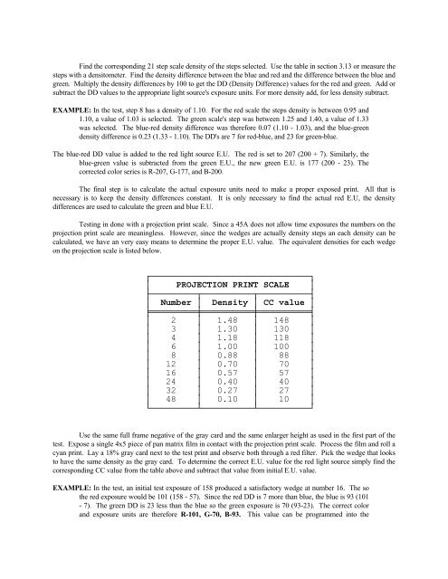
Find the corresponding 21 step scale density of the steps selected. Use the table in section 3.13 or measure the<br />
steps with a densitometer. Find the density difference between the blue and red and the difference between the blue and<br />
green. Multiply the density differences by 100 to get the DD (Density Difference) values for the red and green. Add or<br />
subtract the DD values to the appropriate light source's exposure units. For more density add, for less density subtract.<br />
EXAMPLE: In the test, step 8 has a density of 1.10. For the red scale the steps density is between 0.95 and<br />
1.10, a value of 1.03 is selected. The green scale's step was between 1.25 and 1.40, a value of 1.33<br />
was selected. The blue-red density difference was therefore 0.07 (1.10 - 1.03), and the blue-green<br />
density difference is 0.23 (1.33 - 1.10). The DD's are 7 for red-blue, and 23 for green-blue.<br />
The blue-red DD value is added to the red light source E.U. The red is set to 207 (200 + 7). Similarly, the<br />
blue-green value is subtracted from the green E.U., the new green E.U. is 177 (200 - 23). The<br />
corrected color series is R-207, G-177, and B-200.<br />
The final step is to calculate the actual exposure units need to make a proper exposed print. All that is<br />
necessary is to keep the density differences constant. It is only necessary to find the actual red E.U, the density<br />
differences are used to calculate the green and blue E.U.<br />
Testing in done with a projection print scale. Since a 45A does not allow time exposures the numbers on the<br />
projection print scale are meaningless. However, since the wedges are actually density steps an each density can be<br />
calculated, we have an very easy means to determine the proper E.U. value. The equivalent densities for each wedge<br />
on the projection scale is listed below.<br />
┌───────────────────────────────┐<br />
│ PROJECTION PRINT SCALE │<br />
├─────────┬──────────┬──────────┤<br />
│ Number │ Density │ CC value │<br />
╞═════════╪══════════╪══════════╡<br />
│ 2 │ 1.48 │ 148 │<br />
│ 3 │ 1.30 │ 130 │<br />
│ 4 │ 1.18 │ 118 │<br />
│ 6 │ 1.00 │ 100 │<br />
│ 8 │ 0.88 │ 88 │<br />
│ 12 │ 0.70 │ 70 │<br />
│ 16 │ 0.57 │ 57 │<br />
│ 24 │ 0.40 │ 40 │<br />
│ 32 │ 0.27 │ 27 │<br />
│ 48 │ 0.10 │ 10 │<br />
└─────────┴──────────┴──────────┘<br />
Use the same full frame negative of the gray card and the same enlarger height as used in the first part of the<br />
test. Expose a single 4x5 piece of pan matrix film in contact with the projection print scale. Process the film and roll a<br />
cyan print. Lay a 18% gray card next to the test print and observe both through a red filter. Pick the wedge that looks<br />
to have the same density as the gray card. To determine the correct E.U. value for the red light source simply find the<br />
corresponding CC value from the table above and subtract that value from initial E.U. value.<br />
EXAMPLE: In the test, an initial test exposure of 158 produced a satisfactory wedge at number 16. The so<br />
the red exposure would be 101 (158 - 57). Since the red DD is 7 more than blue, the blue is 93 (101<br />
- 7). The green DD is 23 less than the blue so the green exposure is 70 (93-23). The correct color<br />
and exposure units are therefore R-101, G-70, B-93. This value can be programmed into the