Installation, User Operation, & Maintenance Manual - Anets
Installation, User Operation, & Maintenance Manual - Anets
Installation, User Operation, & Maintenance Manual - Anets

Create successful ePaper yourself
Turn your PDF publications into a flip-book with our unique Google optimized e-Paper software.
<strong>Anets</strong>berger Brothers, Inc.<br />
180 North <strong>Anets</strong> Drive • Northbrook, Illinois 60062 • 847-272-0770 • Fax 847-272-1943<br />
For ANETS Factory Warranty Service • 800-837-2638<br />
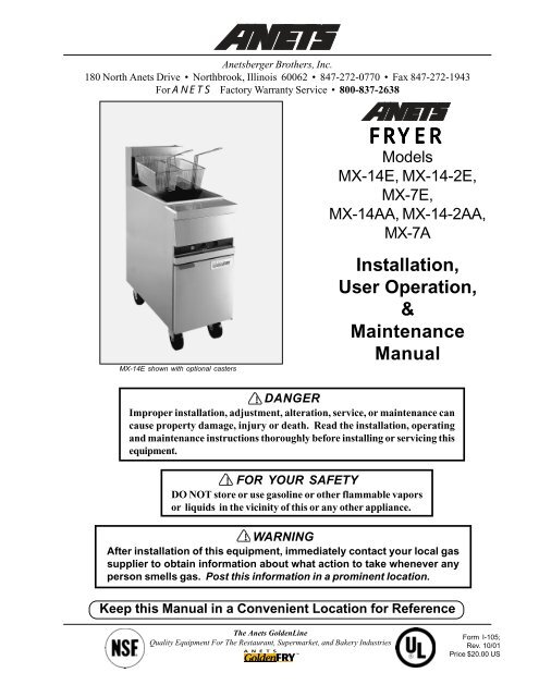
MX-14E shown with optional casters<br />
FRYER<br />
Models<br />
MX-14E, MX-14-2E,<br />
MX-7E,<br />
MX-14AA, MX-14-2AA,<br />
MX-7A<br />
<strong>Installation</strong>,<br />
<strong>User</strong> <strong>Operation</strong>,<br />
&<br />
<strong>Maintenance</strong><br />
<strong>Manual</strong><br />
DANGER<br />
Improper installation, adjustment, alteration, service, or maintenance can<br />
cause property damage, injury or death. Read the installation, operating<br />
and maintenance instructions thoroughly before installing or servicing this<br />
equipment.<br />
WARNING<br />
After installation of this equipment, immediately contact your local gas<br />
supplier to obtain information about what action to take whenever any<br />
person smells gas. Post this information in a prominent location.<br />
!<br />
!<br />
FOR YOUR SAFETY<br />
DO NOT store or use gasoline or other flammable vapors<br />
or liquids in the vicinity of this or any other appliance.<br />
!<br />
Keep this <strong>Manual</strong> in a Convenient Location for Reference<br />
The <strong>Anets</strong> GoldenLine<br />
Quality Equipment For The Restaurant, Supermarket, and Bakery Industries<br />
Form I-105;<br />
Rev. 10/01<br />
Price $20.00 US<br />
1
CONTENTS<br />
Shipping Container Inspection ....................................................... 3<br />
Fryer Gas Supply Specifications .................................................... 4<br />
Fryer Electrical Specifications ....................................................... 5<br />
Figure 1 - Fryer MX-14E Wiring Diagram ............................ 5<br />
Code Requirements ...................................................................... 6<br />
Figure 2 - Fryer Site <strong>Installation</strong> Requirements ....................... 6<br />
<strong>Installation</strong> Requirements ............................................................... 7<br />
<strong>Installation</strong> Instructions .................................................................. 7<br />
Leg <strong>Installation</strong> Instructions ..................................................... 7<br />
Figure 3 - Typical Leg <strong>Installation</strong> ......................................... 8<br />
Leg Leveling Instructions ......................................................... 8<br />
Caster <strong>Installation</strong> Instructions ................................................. 8<br />
Figure 4 - Typical Caster <strong>Installation</strong> ..................................... 9<br />
Caster Leveling Instructions .................................................... 9<br />
Fryer Restraining Device <strong>Installation</strong> Instructions ..................... 10<br />
Gas & Electric Connection Instructions ....................................... 10<br />
Fryer Operating Instructions ........................................................ 11<br />
Fryer Preparation For Use (“Boil Out” Instructions) .............. 12<br />
Figure 5 - Draining the Kettle ............................................... 12<br />
Lighting Procedure ................................................................ 13<br />
Figure 6 - Gas Control Valve & Knob Positions ................... 13<br />
Shutdown Procedure ............................................................ 14<br />
Food Product Frying Time Charts .................................... 15, 16<br />
Daily Cleaning Procedure ....................................................... 17<br />
Monthly <strong>Maintenance</strong> Instructions .......................................... 18<br />
Fryer Troubleshooting Guide ................................................. 19 - 26<br />
Fryer Warranty ............................................................................ 27<br />
2
DANGER<br />
Read these specifications, Code Requirements, <strong>Installation</strong> Requirements, <strong>Installation</strong><br />
Instructions, and Operating Instructions very carefully. Failure to follow the<br />
Instructions could cause the fryer to malfunction. A fryer malfunction can result in<br />
property damage, serious bodily injury, or death.<br />
!<br />
SHIPPING CONTAINER INSPECTION<br />
1. Carefully examine the shipping container for external damage. When damage is noted, notify the<br />
delivery carrier immediately. Save all packing materials for damage claim examination.<br />
2. If no external damage is noted, remove the shipping container from the fryer and examine the fryer<br />
carefully for damage. Place the fryer in a safe location, if damage is noted, so that the freight damage<br />
claims adjuster can examine the fryer.<br />
3. Save the shipping container for use during leg/ caster installation. Refer to the <strong>Installation</strong> Instructions<br />
for that procedure.<br />
Models Covered By This <strong>Manual</strong><br />
MX-14E<br />
MX-14-2E<br />
MX-14-7E<br />
MX-14AA<br />
MX-14-2AA<br />
MX-7A<br />
High Efficiency Stainless Steel Fryer<br />
High Efficiency Stainless Steel Split Pot Fryer<br />
High Efficiency Stainless Steel Half Size Fryer<br />
High Efficiency Stainless Steel Fryer With Automatic Lifts<br />
High Efficiency Stainless Steel Split Pot Fryer With Automatic Lifts<br />
High Efficiency Stainless Steel Half Size Fryer With Automatic Lifts<br />
Standard Accessories furnished in the shipping carton with this fryer include:<br />
Models MX-14AA, -14-2AA, MX-14E, and MX-14-2E Models MX-7A and MX-7E<br />
2 Fryer Baskets 1 Screen 1 Fryer Basket 1 Screen<br />
4 Adjustable Legs 1 Basket Hanger* 4 Adjustable Legs 1 Basket Hanger*<br />
1 Drain Valve Extension 2 Basket Lift Frames ** 1 Drain Valve Extension 1 Basket Lift Frame **<br />
1 Cleanout Rod 1 Cleanout Rod<br />
*- Basket Hanger for MX-14E, MX-14-2E, or MX-7E only.<br />
** - Basket Lift Frame for MX-14AA, MX-14-2AA, or MX-7A only.<br />
NOTE: Other available optional equipment may include a sediment tray; a microprocessor-based cooking<br />
computer with shortening melter, boil-out mode, and digital timers (Fri-tronic ® ); a built-in filter system<br />
(Filtronic II or Filter Mate ); a fryer cover; a drain table; a front drain tray; or four casters.<br />
NOTE: A Parts List for each <strong>Anets</strong> Fryer is among the items shipped with each fryer. If an additional<br />
copy of this list is needed, please contact the factory as directed on the back cover.<br />
3
FRYER GAS SUPPLY SPECIFICATIONS<br />
Please make sure that your desired fryer location has gas<br />
supply factors that are suitable for this product:<br />
Models MX-14E, MX-14-2E, MX-14AA, &MX-14-2AA<br />
INPUT REQUIRED:<br />
111,000 BTU/Hr *<br />
Natural Gas<br />
Propane Gas<br />
MANIFOLD PRESSURE<br />
SUPPLY PRESSURE***<br />
3½“ W.C. ** 10“ W.C.<br />
6“ W.C., minimum 11“ W.C., minimum<br />
Models MX-7E & MX-7A<br />
INPUT REQUIRED:<br />
55,000 BTU/Hr *<br />
Natural Gas<br />
Propane Gas<br />
MANIFOLD PRESSURE 3½“ W.C. ** 10“ W.C.<br />
SUPPLY PRESSURE*** 6“ W.C., minimum 11“ W.C., mini-<br />
* - BTU/Hr Rating is based on sea level operation. For sites above 2000 feet, reduce this rating 4% for<br />
each 1000 feet above sea level.<br />
** - “ W.C. = Inches, Water Column.<br />
*** - Measure Supply Pressure when all other gas-powered equipment is operating.<br />
Gas Supply Inlet Pipe must be ¾” NPT (National Pipe Thread) standard gas line. The gas supply inlet<br />
line should be as straight as possible (fewest bends or elbows) to obtain the highest available gas pressure at<br />
the appliance. Locate this inlet line horizontally at the center of the desired fryer location, approximately<br />
8¼” above the floor.<br />
NOTE: Using a flexible inlet line permits variation in the gas supply line location, both horizontally and<br />
vertically.<br />
<strong>Anets</strong> fryers are only for use with the type of gas specified on the spec plate. If a fryer requires modification<br />
to use a gas other than that which is identified on the fryer spec plate, contact your <strong>Anets</strong> representative or<br />
call (800) 837-2638.<br />
4
FRYER ELECTRICAL SPECIFICATIONS<br />
Please make sure that your desired fryer location has electrical<br />
supply factors that are suitable for this product:<br />
120 Volts, 60 Hz, (Refer to Table 1 for amperage requirements), 1-phase, three-wire connection, including<br />
an electrical ground, via a dedicated circuit breaker. A model-specific electrical circuit diagram is<br />
mounted inside the front door of each fryer.<br />
Table 1. Fryer Amperage<br />
Requirements<br />
Model<br />
Amperage<br />
MX-14E<br />
MX-14-2E<br />
MX-7E<br />
MX-14AA<br />
MX-14-2AA<br />
MX-7A<br />
2 A.<br />
4 A.<br />
2 A.<br />
7 A.<br />
9 A.<br />
5 A.<br />
Install a dedicated, three-prong, outlet/ receptacle<br />
within 5 feet of the desired fryer location to allow<br />
the fryer’s power cable to be connected. Ensure<br />
that the green (ground) wire of the fryer’s power<br />
cable is attached to the fryer’s structure, providing<br />
an electrical ground in accordance with applicable<br />
local codes, or in the absence of local codes, with<br />
the National Electrical Code, ANSI/NFPA 70<br />
(latest edition) or the Canadian Electrical Code,<br />
CSA C22.1 (latest edition) and CSA C22.2 (latest<br />
edition).<br />
!<br />
WARNING<br />
Electrical Grounding Instructions<br />
(See inside of door for wiring diagram.)<br />
This appliance is equipped with a threeprong<br />
(grounding) plug for your protection<br />
against shock hazard, and should<br />
be plugged directly into a properly<br />
grounded, three-prong receptacle. DO<br />
NOT cut or remove the grounding prong<br />
from this plug.<br />
Figure 1 is the basic wiring diagram of an<br />
MX-series fryer showing a typical circuit.<br />
Some fryers may have other options that do<br />
not appear in this basic wiring diagram. A<br />
model-specific wiring diagram included with<br />
each fryer shows all the actual parts and<br />
their associated wiring connections. In<br />
addition, fryers equipped with a built-in filter<br />
system (Filtronic II or Filter Mate) and/or<br />
built-in computer controls (Fri-tronic) have<br />
a supplementary manual included for each<br />
option.<br />
Figure 1. Fryer Model MX-14E Wiring Diagram<br />
5
IMPORTANT: Read the Code Requirements<br />
and the <strong>Installation</strong> Requirements and Iinstructions<br />
carefully, before starting the installation.<br />
Contact the factory (800/ 837-2638) if any<br />
problems or questions arise.<br />
The fryer installation must conform with local<br />
codes, or in the absence of local codes, with the<br />
National Fuel Gas Code, ANSI Z223.1 (latest<br />
edition); the Natural Gas <strong>Installation</strong> Code, CAN/<br />
CGA-B149.1 (latest edition); or the Propane Gas<br />
<strong>Installation</strong> Code, CAN/CGA-B149.2 (latest<br />
edition), as applicable, including:<br />
a. Disconnect the fryer and its individual shutoff<br />
valve from the gas supply piping system during<br />
any pressure testing of the gas supply system at<br />
test pressures in excess of ½ psig (3.45 kPa).<br />
b. Isolate the fryer from the gas supply piping<br />
system during any pressure testing of the gas<br />
supply system at test pressures equal to or less<br />
than ½ psig (3.45 kPa).<br />
c. For fryers utilizing floor casters, the fryer installation<br />
shall be made with a connector that<br />
complies with the Standard for Connectors for<br />
Movable Gas Appliances, ANSI Z21.69<br />
(latest edition) or CAN/CGA 6.16 (latest<br />
edition), and a quick-disconnect device that<br />
complies with the Standard for Quick-Disconnect<br />
Devices for Use with Gas Fuel, ANSI<br />
Z21.41 or CAN/CGA 1-6.9 (latest edition).<br />
CODE REQUIREMENTS<br />
d. Restrict the movement of a caster-equipped<br />
fryer by using a limiting device (for example, a<br />
cable attached both to the fryer and to a fixture<br />
attached to the site structure) to avoid<br />
depending on the connector and the quickdisconnect<br />
device or its associated piping to<br />
limit fryer movement.<br />
e. Install this fryer on a non-combustible floor<br />
with its back and sides at least 6” away from<br />
any combustible wall, as shown in Figure 2.<br />
!<br />
WARNING<br />
Install this fryer under a ventilation<br />
hood that conducts combustion products<br />
outside the building. Venting<br />
must comply with ANSI/NFPA 96<br />
(latest edition).<br />
f. Install this fryer in a location where adequate<br />
combustion and ventilation air is available.<br />
Keep the area directly in front of the fryer open<br />
for adequate air flow to the burners. DO<br />
NOT obstruct the flow of combustion and<br />
ventilation air.<br />
g. Keep the fryer area free and clear from<br />
combustibles and debris.<br />
h. Attach a restraining device to each fryer, to<br />
prevent the unit from tipping, which could<br />
cause splashing of hot liquid .<br />
From the top of the flue on<br />
the fryer, allow a minimum<br />
of at least 10 inches vertical<br />
clearance beneath a<br />
ventilating hood.<br />
Figure 2. Fryer Site <strong>Installation</strong> Requirements<br />
6
INSTALLA<br />
ALLATION REQUIREMENTS<br />
Install the fryer in accordance with the preceding<br />
Code Requirements, as well as the following<br />
<strong>Installation</strong> Requirements.<br />
1. DO NOT install this fryer in a mobile home,<br />
trailer, or recreational vehicle.<br />
2. Install this fryer in a location that has the fryer’s<br />
electrical receptacle nearby (5 feet or less<br />
away) to avoid straining the fryer’s power<br />
cord. (See Figure 2.)<br />
3. Install this fryer in a location that allows it to be<br />
moved away from other adjacent appliances<br />
for cleaning and maintenance.<br />
NOTE: If the fryer is installed among<br />
a row of appliances (“banked”), with<br />
its only convenient movement forward,<br />
sufficient room must be available in<br />
front of the fryer to permit its separation<br />
from adjacent appliances for<br />
cleaning and maintenance.<br />
4. Tightly fasten the legs (or casters) to the bottom<br />
of the fryer using the supplied hardware, to<br />
prevent the fryer from tipping, wobbling or<br />
rocking when it is in its desired location. Refer<br />
to the following Leg <strong>Installation</strong> Instructions<br />
or Caster <strong>Installation</strong> Instructions for leg<br />
or caster attachment and leveling information.<br />
! CA<br />
CAUTION:<br />
Hood make-up air<br />
MUST NOT flow in a manner that<br />
restricts or impedes the natural flow<br />
of combustion or ventilation air.<br />
5. Confirm that the air from the ventilation hood<br />
flowing near the fryer after installation is NOT<br />
blowing on the rear of the unit, to prevent<br />
affecting the burner flames and possibly causing<br />
damage to plastic parts.<br />
LEG INSTALLATION<br />
INSTRUCTIONS<br />
INSTALLA<br />
ALLATION INSTRUCTIONS<br />
1. Flatten the shipping carton (after unpacking the<br />
fryer and its parts and accessories) for fryer<br />
surface protection during leg installation.<br />
2. Position the side of the fryer flat on the carton,<br />
exposing the fryer bottom mounting brackets<br />
for leg installation, as shown in Figure 3.<br />
3. Place the leg mounting plate flush against the<br />
mounting bracket on the fryer bottom, while<br />
aligning the mounting holes.<br />
4. Insert one mounting bolt through a flat washer<br />
and then through the proper hole in the fryer<br />
mounting bracket and through the leg mounting<br />
plate.<br />
5. Screw a locking nut several turns onto the<br />
mounting bolt.<br />
6. Repeat steps 4 and 5 until all four mounting<br />
bolts for a leg are in place with locking nuts.<br />
7. Tighten the four locking nuts evenly and securely<br />
to hold the leg mounting plate against the<br />
fryer bottom mounting bracket.<br />
7
INSTALLA<br />
ALLATION INSTRUCTIONS<br />
UCTIONS (Continued)<br />
Figure 3. Typical Leg <strong>Installation</strong><br />
LEG LEVELING INSTRUCTIONS<br />
1. Move the fryer to its desired location.<br />
!<br />
WARNING<br />
The fryer MUST NOT tip, rock or wobble,<br />
to avoid splashing or spilling its HOT<br />
shortening contents during operation.<br />
2. Turn the screw-type leg adjustment ends as<br />
necessary to level the fryer, until NO tipping,<br />
rocking, or wobbling is evident.<br />
3. Perform the Fryer Restraining Device<br />
<strong>Installation</strong> Instructions, referring to<br />
Figure 2.<br />
CASTER INSTALLATION<br />
INSTRUCTIONS<br />
1. Flatten the shipping carton (after unpacking the<br />
fryer and its parts and accessories) for surface<br />
protection during caster installation.<br />
2. Position the side of the fryer flat on the carton,<br />
exposing the fryer bottom mounting brackets<br />
for caster installation, as shown in Figure 4.<br />
3. Mount locking casters on the front of the fryer<br />
and fixed casters on the rear, by placing each<br />
caster mounting plate flush against the mounting<br />
bracket on the fryer bottom.<br />
4. Insert one mounting bolt through a flatwasher<br />
(supplied) and the mounting bracket, then<br />
through the caster mounting plate.<br />
5. Screw a locking nut several turns onto the<br />
mounting bolt.<br />
6. Repeat steps 4 and 5 until all four mounting<br />
bolts for a caster are in place with locking nuts.<br />
7. Tighten the four bolts evenly and securely to<br />
hold the caster mounting plate against the fryer<br />
mounting bracket.<br />
8
INSTALLA<br />
ALLATION INSTRUCTIONS<br />
UCTIONS (Continued)<br />
Figure 4. Typical Caster <strong>Installation</strong><br />
CASTER LEVELING INSTRUC-<br />
TIONS<br />
1. Move the fryer to its desired location.<br />
2. Determine whether the fryer tends to wobble<br />
or rock when in its desired location. If it<br />
does, perform steps 3 through 9. If it does<br />
not, skip to step 10, then proceed to the<br />
<strong>Installation</strong> Instructions.<br />
!<br />
WARNING<br />
The fryer MUST NOT tip, rock or wobble,<br />
to avoid splashing or spilling its HOT<br />
shortening contents during operation.<br />
3. Determine which caster requires adjustment<br />
and the approximate amount of change<br />
required to level the fryer.<br />
4. Position the side of the fryer on the shipping<br />
carton, exposing the bottom of the fryer<br />
with the caster mounting plates (Figure 4).<br />
5. Completely unscrew the bolts holding the<br />
caster mounting plate that requires the leveling<br />
adjustment. Retain the locking nuts for later<br />
reassembly.<br />
CASTER LEVELING<br />
INSTRUCTIONS (Continued)<br />
6. Reinsert each bolt through its flatwasher and<br />
the fryer mounting bracket; next, place a<br />
spacer of the required size on the bolt before<br />
inserting the bolt through its mounting hole on<br />
the caster mounting plate and screwing a<br />
locking nut onto the bolt.<br />
7. Repeat step 6 for all remaining bolts.<br />
8. Tighten all four locking nuts evenly and securely<br />
against the caster mounting plate and<br />
the fryer bottom mounting bracket.<br />
9. Return the fryer to its desired location. Lock<br />
the front casters to prevent fryer movement<br />
and check again for wobbling or rocking.<br />
Repeat steps 3 through 9 until no wobbling<br />
or rocking occurs. When the fryer no<br />
longer wobbles or rocks, perform step 10.<br />
10. Perform the Fryer Restraining Device<br />
<strong>Installation</strong> Instructions, referring to<br />
Figure 2.<br />
9
INSTALLA<br />
ALLATION INSTRUCTIONS<br />
(Continued)<br />
FRYER RESTRAINING DEVICE INSTALLATION INSTRUCTIONS<br />
WARNING<br />
Fryers MUST have a movementlimiting<br />
(restraining cable) device<br />
installed to prevent tipping that<br />
causes splashing or spilling its HOT<br />
contents.<br />
!<br />
NOTE: This movement-limiting device<br />
is to be furnished and installed<br />
by the fryer’s installing<br />
contractor before the fryer is connected<br />
to the gas line at its desired<br />
location.<br />
1. Install one restraining device connector into<br />
the structure wall directly behind the fryer’s<br />
desired location, as shown in Figure 2.<br />
2. Install one restraining device connector on the<br />
rear panel of the fryer very close to the quickdisconnect<br />
device on the end of the fryer’s gas<br />
line.<br />
NOTE: Avoid interfering with the lift<br />
mechanism, on AA models.<br />
3. Attach one end of the restraining cable to the<br />
wall connector. Attach the other end to the<br />
fryer connector.<br />
4. Confirm that the fryer cannot move far enough<br />
away from the wall to cause excessive movement<br />
of the flexible gas line or its associated<br />
connectors.<br />
GAS & ELECTRIC CONNECTION INSTRUCTIONS<br />
Installing your ANETS Fryer requires the following<br />
procedure, after its legs or casters are properly<br />
attached and it is in its desired location.<br />
1. Ensure that the gas control valve knob in the<br />
fryer has its OFF position next to the valve<br />
mark.<br />
2. Ensure that the gas supply inlet line valve is<br />
closed (handle crosswise to the line direction).<br />
3. Ensure that the circuit breaker dedicated to<br />
this fryer is OFF and that all fryer controls are<br />
set to OFF.<br />
4. Connect the ¾” gas supply line to the gas line<br />
adapter on the lower rear of the fryer.<br />
!<br />
WARNING<br />
DO NOT use a flame to check for leaks.<br />
5. Open the gas supply line valve (handle in-line<br />
with line direction); then, confirm that all gas<br />
supply line joints and couplings are free of<br />
leaks using soap suds or a leak-check solution,<br />
after the fryer is in its desired location.<br />
6. Plug the fryer’s electric power cord plug into<br />
the receptacle specified for this fryer. Switch<br />
the circuit breaker to ON.<br />
7. Refer to Fryer Operating Instructions to<br />
begin using your ANETS Fryer.<br />
10
FRYER OPERATING INSTRUCTIONS<br />
!<br />
CAUTION<br />
DO NOT operate this fryer during a power outage or interruption of gas<br />
service. Turn all fryer controls to OFF, including the gas control valve knob,<br />
then close the gas supply line valve. Also, switch off the circuit breaker<br />
controlling electric power to the fryer. When notified that the power outage<br />
has ended, perform the Lighting Procedure (later in this manual).<br />
DANGER<br />
NEVER operate this fryer when its flue is blocked or when the<br />
ventilation hood is not on because the combustion products<br />
can accumulate and cause serious injury or death.<br />
!<br />
DANGER<br />
Avoid moving the fryer while it contains<br />
HOT shortening. Drain the shortening from<br />
the fryer before moving it for service, cleaning,<br />
or maintenance to avoid spilling or<br />
splashing. Burns from hot shortening can<br />
cause serious injury or death.<br />
!<br />
A. An ANETS MX-14E or MX-14AA<br />
Fryer is designed for operation with a kettle<br />
filled with approximately 35 to 50 pounds of<br />
liquid shortening. (This is approximately 3½<br />
to 6 gallons.)<br />
Each kettle of an ANETS MX-14-2AA,<br />
MX-14-2E, MX-7A, or MX-7E Fryer is<br />
designed for operation with approximately 25<br />
pounds of liquid shortening. (This is approximately<br />
2½ to 3 gallons.)<br />
! CAUTION: Unless this fryer is<br />
equipped with the controls permitting<br />
the melting of shortening*,<br />
DO NOT melt solid shortening in<br />
this fryer because the melting can<br />
damage the kettle, which will void<br />
the fryer warranty.<br />
* Fryers that are shipped with multiproduct<br />
cooking computers (Fritronic<br />
) have an automatic ‘Melt’<br />
selection to liquefy solid shortening.<br />
Shortening must be melted into the liquid state<br />
before it can be used in an ANETS Fryer,<br />
unless the fryer has an automated ‘melt’<br />
selection available on its control panel.<br />
B. Schedule regular cleanings of the fryer to<br />
ensure long-term satisfactory operation.<br />
Refer to the Daily Cleaning Procedure,<br />
later in this manual.<br />
C. Before servicing and maintenance, allow the<br />
fryer to cool. ALWAYS shut off electricity<br />
and gas to the fryer while working on it, to<br />
prevent electric shocks or burns.<br />
D. Contact the factory (800-837-2638) for warranty<br />
service authorization. [Always notify<br />
the factory the next business day about<br />
‘after-hours’ warranty service.] Contact<br />
your local restaurant equipment service<br />
agency for other service, repairs, or maintenance<br />
activities, as necessary.<br />
E. When breaded food products are being<br />
cooked, ANETS recommends using the<br />
special (optional) sediment tray to capture<br />
any breading fragments that become loosened<br />
from the food product. Periodic clearing of<br />
the sediment tray reduces premature contamination<br />
of the liquid shortening from breading<br />
fragments.<br />
11
FRYER OPERATING INSTRUCTIONS<br />
(Continued)<br />
FRYER PREPARATION FOR USE<br />
“BOIL OUT” INSTRUCTIONS<br />
New ANETS Fryers are cleaned and leak-tested<br />
at the factory before shipping. Before using a<br />
newly installed fryer for food preparation, clean the<br />
kettle again, as follows:<br />
1. Thoroughly wipe the interior of the kettle<br />
with clean cloths. Open the front door on<br />
the lower portion of the fryer to access the<br />
drain ball valve. Open the drain ball valve<br />
(by aligning the valve handle with the drain<br />
ball valve) and wipe the entire drain line clean.<br />
2. Close the drain ball valve (turn the valve handle<br />
cross-wise to the drain ball valve). Fill<br />
the kettle with water to about 3“ from the<br />
top. Add 1 to 2 cups of low sudsing soap<br />
powder, washing soda (trisodium phosphate),<br />
or deep fat fryer kettle cleaner.<br />
3. Perform the Lighting Procedure for the<br />
fryer. (Refer to the Lighting Procedure<br />
later in this manual.)<br />
4. Set the thermostat to 190°F. Heat, but DO<br />
NOT boil the water. Stir the water to dissolve<br />
the cleaning material.<br />
!<br />
WARNING<br />
Hot cleaning solution can cause severe<br />
burns. Take care when handling hot<br />
cleaning solution to avoid spilling or splashing<br />
the solution.<br />
5. Clean the fryer kettle for at least 20 minutes.<br />
Use a small hand mop (an optional brush can<br />
be ordered for this purpose) to clean the<br />
upper portion of the kettle (above the 3“<br />
waterline) and the top rim of the kettle.<br />
6. Shut down the fryer using the Shutdown<br />
Procedure for the fryer. Refer to the Shutdown<br />
Procedure later in this manual. For<br />
safety, allow the water to cool (below 140ºF)<br />
before draining.<br />
FRYER PREPARATION FOR USE<br />
(Continued)<br />
!<br />
CAUTION<br />
For a fryer with a built-in filter system, DO<br />
NOT pump the cleaning (or rinsing) solution<br />
through the filter system, to avoid damaging<br />
the filter system pump.<br />
7. Open the front door and mount the drain<br />
extension to the drain ball valve. Position a<br />
container (bucket) capable of holding HOT<br />
cleaning solution beneath the end of the drain<br />
extension to hold the cleaning solution being<br />
drained, as shown in Figure 5.<br />
Figure 5. Draining The Kettle<br />
8. Open the drain ball valve SLOWLY, to avoid<br />
splashes while draining the cleaning solution<br />
from the kettle.<br />
9. Close the drain ball valve (valve handle<br />
cross-wise) and remove the drain extension.<br />
Close the front door.<br />
10. Safely dispose of the cleaning solution.<br />
11. Fill the kettle with water to about 3“ from<br />
the top. Add 2 cups of vinegar to neutralize<br />
the cleaning solution.<br />
12. Repeat steps 3 through 10 of this procedure.<br />
13. Thoroughly wipe the interior of the kettle and<br />
the drain ball valve with clean, dry, wiping<br />
cloths to remove ALL water.<br />
14. Dry the kettle thoroughly because any remaining<br />
water can cause spattering of hot<br />
shortening when the kettle is later filled and<br />
heated.<br />
12
OFF<br />
FRYER OPERATING INSTRUCTIONS<br />
UCTIONS (Continued)<br />
Normal operation of an ANETS Fryer requires that the kettle is filled with liquid shortening above the<br />
lower indent level, marked on the rear of the kettle, before lighting the fryer’s pilot and turning on the main<br />
burner.<br />
!<br />
CAUTION: Shortening MUST be in liquid form to avoid scorching or discoloration and possible<br />
damage to the kettle. Damage caused by melting solid shortening will NOT be covered by the warranty.<br />
LIGHTING PROCEDURE<br />
NOTE: The gas line of a new fryer installation<br />
may contain a considerable amount of air which<br />
will hinder immediate lighting. You may have to<br />
press down the control knob for as long as several<br />
minutes until the pilot flame burns steadily.<br />
1. Switch the circuit breaker controlling electric<br />
power to the fryer to ON.<br />
2. Ensure that the fryer’s thermostat knob is set<br />
to OFF.<br />
3. Open the gas supply line inlet valve to the<br />
fryer by aligning the gas valve handle with the<br />
gas line piping.<br />
4. Open the front door and move the right pilot<br />
viewing/lighting port cover aside.<br />
5. Turn the gas control valve knob to align the<br />
PILOT setting with the valve mark. Figure 6<br />
shows the possible control knob positions.<br />
6. Press, and hold down, the gas control knob<br />
to allow pilot gas to flow. Push the spark<br />
igniter pushbutton several times, until the pilot<br />
flame lights. Continue holding down the control<br />
knob for at least 30 seconds until the<br />
pilot flame burns steadily, without going out.<br />
NOTE: A match may also be used to<br />
light the pilot flame.<br />
7. Release the control knob and observe that<br />
the pilot flame remains lighted. Close the<br />
right pilot viewing/lighting port.<br />
8. Light the left pilot flame by opening the left<br />
pilot viewing/lighting port and applying a<br />
match to ignite the pilot flame. Close the<br />
left pilot viewing/lighting port.<br />
!<br />
CAUTION: Ensure that both pilot<br />
viewing/lighting ports are closed, to<br />
prevent excessive heat from damaging<br />
the gas controls.<br />
9. Turn the gas control valve knob to align the<br />
ON setting with the valve mark.<br />
10. Close the front door and switch the fryer<br />
POWER switch ON.<br />
NOTE: A fryer equipped with built-in filtering<br />
system (Filtronic or Filter Mate)<br />
requires the front door to be closed before<br />
switching the POWER switch to ON.<br />
11. Turn the thermostat knob to the desired<br />
temperature.<br />
Valve<br />
Mark<br />
PI LOT<br />
ON<br />
Valve<br />
Mark<br />
PI LOT<br />
OFF<br />
Valve<br />
Mark<br />
OFF PILOT ON<br />
Figure 6. Gas Control Valve & Knob Positions<br />
ON<br />
ON<br />
OFF<br />
PI LOT<br />
13
FRYER OPERATING INSTRUCTIONS<br />
SHUTDOWN PROCEDURE<br />
UCTIONS (Continued)<br />
NOTE: Shutdown is recommended at the end of<br />
a workday or whenever no frying is required for a<br />
period of several hours. The fryer MUST be<br />
shutdown during any power outage or interruption<br />
of gas service. To prevent damage, the fryer<br />
MUST also be shutdown whenever there is no<br />
shortening in the kettle.<br />
1. Turn the thermostat knob to OFF.<br />
2. Turn the gas control valve knob to align the<br />
PILOT setting with the valve mark.<br />
3. Open the pilot viewing/lighting port to confirm<br />
that only the pilot flame remains lighted.<br />
4. Press, and turn, the gas control valve<br />
knob to align the OFF setting with the valve<br />
mark. Observe that the pilot flame goes out.<br />
5. Switch the POWER switch to OFF.<br />
NOTE: For extended periods of non-use<br />
or when servicing the fryer, close the gas<br />
supply line inlet valve to the fryer by turning<br />
the gas valve handle cross-wise with the gas<br />
line piping. Also, switch the circuit breaker<br />
for this fryer to the OFF position.<br />
14
FRYER OPERATING INSTRUCTIONS<br />
UCTIONS (Continued)<br />
Load the fryer basket with the food product while the basket is not in the hot liquid shortening. DO<br />
NOT overload the fryer basket. Load only a premeasured quantity of food product (1½ lb per<br />
basket, or less, if smaller portions are desired).<br />
`<br />
Model MX-14AA and MX-7A Fryers ONLY: Place the loaded fryer basket on the basket lifter frame<br />
and turn the timer control knob to the desired cooking time; press the pushbutton of the timer control<br />
to lower the loaded basket into the hot liquid shortening. When the basket of cooked food product<br />
rises from the hot liquid shortening, let it drain for approximately 15 - 30 seconds before serving.<br />
Fryers equipped with multi-product cooking computers: Consult the instructions provided with<br />
those fryers.<br />
NEVER increase the thermostat setting above the recommended setting to reduce the cooking time;<br />
this will produce a lower quality product and will cause more rapid shortening breakdown.<br />
RECOMMENDED FRYING TIME FOR POTATOES<br />
French Fries<br />
(Typical, 1½ lb loads)<br />
Raw to Done<br />
Blanched, only<br />
Browned, only<br />
Size<br />
1/4” cut<br />
1/4” cut<br />
1/4” cut<br />
ANETS<br />
High Performance<br />
Fryer<br />
Frying<br />
Time<br />
(minutes)<br />
340° F. 5<br />
2½<br />
2½<br />
Raw to Done<br />
Blanched, only<br />
Browned, only<br />
3/8” cut<br />
3/8” cut<br />
3/8” cut<br />
6<br />
3<br />
3<br />
Commercially Treated<br />
Frozen, Fat Blanched<br />
3/8” cut<br />
3/8” cut<br />
6<br />
2<br />
Raw to Done<br />
Blanched, only<br />
Browned, only<br />
1/2” cut<br />
1/2” cut<br />
1/2” cut<br />
340° F.<br />
7<br />
4<br />
3<br />
RECOMMENDED FRYING TIME FOR CHICKEN<br />
(Depending on Piece Size)<br />
Chicken<br />
Croquettes (Nuggets)<br />
Pre-cooked, Breaded Pieces<br />
Raw to Done, Pieces*<br />
Tenders<br />
ANETS<br />
High Performance<br />
Fryer<br />
Frying<br />
Time<br />
(minutes)<br />
340° F. 3 - 4<br />
3 - 4<br />
12 - 15<br />
340° F.<br />
5<br />
* - Usual per order = Wing, Leg, Breast, Thigh (1/2 chicken)<br />
15
FRYER OPERATING INSTRUCTIONS<br />
UCTIONS (Continued)<br />
RECOMMENDED FRYING TIME FOR POPULAR FRIED FOODS<br />
Food Product<br />
Breaded Foods<br />
Calamari<br />
Cauliflower, Pre-cooked<br />
Cheese Sticks<br />
Clams<br />
Egg Plant, Pre-cooked<br />
Mushrooms<br />
Oysters<br />
Onion Rings<br />
Tamale Sticks<br />
Veal Cutlet<br />
Calzone (Pizza Puffs)<br />
Corn-on-the-Cob (Fresh)<br />
Corn Dogs<br />
Donuts, Hand-Cut, Cake<br />
Donuts, Yeast, Raised<br />
Fritters<br />
French-toasted Sandwiches<br />
Frozen Breaded Shrimp<br />
Fresh Breaded Shrimp<br />
Frozen Fish Fillets<br />
Fresh Fish Fillets<br />
Fresh Breaded Scallops<br />
Frozen Fish Sticks<br />
Glazed Cinnamon Apples<br />
Tortilla Chips*<br />
Turnovers<br />
ANETS<br />
High Performance<br />
Fryer<br />
340° F. 2½ - 3<br />
3<br />
3<br />
1<br />
3<br />
2½ - 3<br />
5<br />
2½ - 3<br />
3<br />
3 - 4<br />
340° F.<br />
Frying<br />
Time<br />
(minutes)<br />
3 - 4<br />
3½ - 4<br />
3½<br />
1½<br />
1<br />
3<br />
1<br />
4<br />
3<br />
5 - 7<br />
3<br />
4<br />
4<br />
3 - 5<br />
2 - 2½<br />
5 - 7<br />
* - Use a second basket on top of the chips in the bottom basket, to keep them<br />
within the hot shortening; otherwise, they float before cooking completely.<br />
16
FRYER OPERATING INSTRUCTIONS<br />
UCTIONS (Continued)<br />
DAILY CLEANING PROCEDURE<br />
NOTE: Cleaning is recommended at the end of<br />
a workday, to prepare the fryer for proper operation<br />
the next time it is to be used.<br />
!<br />
DANGER<br />
DO NOT move the fryer while it contains<br />
HOT shortening. Allow it to cool and<br />
drain the shortening from the fryer before<br />
moving it for service, cleaning or<br />
maintenance to avoid spilling or splashing.<br />
[Refer to steps 1 through 7.] Burns<br />
from HOT shortening can cause serious<br />
injury or death.<br />
When cleaning, if relocation of your fryer is<br />
necessary, disconnect the gas supply line and<br />
unplug the electric power cable to the fryer. Also,<br />
if your fryer is caster-equipped, unlock the locking<br />
casters and disconnect the movement-limiting<br />
cable. Move the fryer as necessary to allow the<br />
following cleaning procedure to occur:<br />
1. Open the front door of the fryer. Attach the<br />
drain extension to the drain ball valve.<br />
2. Perform the Shutdown Procedure. Ensure<br />
that the gas supply line inlet valve is closed<br />
(handle cross-wise to pipe line) and the pilot<br />
flame is extinguished.<br />
3. Position a steel drum [NEVER use plastic!]<br />
with a filter cone directly beneath the drain<br />
extension end, OR if your fryer is equipped<br />
with an ANETS Filtronic II or Filter<br />
Mate unit, refer to that equipment’s manual<br />
for operation details.<br />
4. Remove the fryer baskets and the sediment<br />
tray, if present, from the fryer. (If the screen<br />
is present, use the cleanout rod to lift it from<br />
the hot shortening, to avoid burns.) Clean,<br />
and rinse, these items in the sink. MAKE<br />
SURE that these items are completely dry<br />
before their next use.<br />
DAILY CLEANING PROCEDURE<br />
(Continued)<br />
5. Allow shortening to cool before draining.<br />
Slowly open the drain ball valve to drain the<br />
shortening. Take care to avoid spilling or<br />
splashing the shortening.<br />
6. Carefully use the Cleanout Rod to clear any<br />
sediment blocking the kettle drain. Flush out<br />
all sediment in the bottom of the kettle by<br />
pouring filtered liquid shortening into the kettle<br />
until the shortening being drained runs<br />
clear.<br />
7. Close the drain ball valve, after the kettle is<br />
completely empty of shortening and sediment.<br />
Detach the drain extension. Clean,<br />
rinse, and dry it before storing (on door<br />
bracket).<br />
!<br />
WARNING<br />
Wait until the kettle has cooled<br />
before performing step 8, to<br />
avoid injury from burns.<br />
8. Thoroughly wipe the kettle interior using<br />
clean cloths.<br />
9. Periodically perform the “BOIL OUT”<br />
Instructions to ensure thorough cleaning of<br />
the kettle. ( Refer to the earlier FRYER<br />
PREPARATION FOR USE section.)<br />
10. Return the fryer to its normal operating location<br />
and reconnect both the gas supply line<br />
and the movement-limiting cable. Plug the<br />
electric power cable into its receptacle. (For<br />
caster-equipped fryers, lock the locking casters<br />
to prevent movement.)<br />
11. Refill the kettle with filtered (or fresh) liquid<br />
shortening to the desired indent mark on the<br />
rear wall of the kettle, only if fryer operation<br />
is to continue during a subsequent shift.<br />
Otherwise, melt shortening into its liquid state<br />
and refill the kettle before fryer operation is<br />
17
FRYER OPERATING INSTRUCTIONS<br />
DAILY CLEANING PROCEDURE<br />
(Continued)<br />
scheduled during the next normal working<br />
shift.<br />
12. Return the screen (or, if used, the sediment<br />
tray) to its proper position in the kettle.<br />
Place the fryer baskets on the basket hanger<br />
(or the lifter frame) for this fryer.<br />
13. Perform the Lighting Procedure to return<br />
the fryer to operation, when desired.<br />
UCTIONS (Continued)<br />
MONTHLY MAINTENANCE INSTRUCTIONS<br />
NOTE: Regular maintenance is recommended to<br />
keep the fryer operating properly.<br />
Once each month, before beginning fryer operation,<br />
check the flue (behind the backsplash panel)<br />
to ensure that it is clear and free of obstructions,<br />
enabling exhaust combustion gases to flow freely<br />
toward the ventilation hood area. DO NOT allow<br />
the flue to become excessively dirty, NEVER<br />
allow the flue to be blocked.<br />
Monthly, observe the condition of the ventilation<br />
hood. If it shows evidence of a great deal of<br />
greasy residue, remove (clean) the residue to allow<br />
free flow of ventilation air.<br />
18
FRYER<br />
TROUBLESHOO<br />
OUBLESHOOTING GUIDE<br />
All service (repairs or part replacement) must be performed by a qualified Service Agency.<br />
PROBLEM CAUSE REMEDY<br />
Pilot (piezo-electric)<br />
pushbutton igniter does<br />
not light the pilot flame.<br />
Pilot flame does not<br />
stay lighted.<br />
1. Electrode of igniter out of position or<br />
dirty/sooty electrode.<br />
2. Loose spark wire; loose igniter nut.<br />
3. Piezo-electric igniter does not generate a<br />
spark.<br />
1. Dirty/sooty pilot burner.<br />
2. Low gas supply pressure [less than 6”<br />
W.C. for natural gas; (11” W.C. for propane)<br />
when all other gas-powered equipment<br />
is operating].<br />
3. Pilot flame too small to heat thermocouple.<br />
4. Pilot flame ‘wavering’ (being blown about<br />
by a draft).<br />
5. Improper thermocouple output voltage<br />
(must be at least 10 millivolts, measured at<br />
the thermocouple junction block).<br />
6. High-limit thermostat problem has shut off<br />
the gas.<br />
1. Move electrode within 3/16” of<br />
pilot burner tip. Clean the<br />
electrode.<br />
2. Check spark wire connection at<br />
the igniter nut and make sure<br />
the connection is tight.<br />
3. Replace igniter mechanism<br />
(portion with pushbutton).<br />
1. Clean the pilot burner. Perform<br />
the Lighting Procedure.<br />
2. Measure the gas supply pressure.<br />
Contact your local gas supplier<br />
to obtain adequate gas supply<br />
pressure.<br />
3. Adjust the pilot valve (part of<br />
the gas control valve) to increase<br />
the flame size: Unscrew<br />
and retain the slotted<br />
threaded cover; turn the pilot<br />
valve adjustment screw two<br />
turns counterclockwise;<br />
reinstall the threaded cover.<br />
4. Block or redirect the draft, to<br />
keep the flame burning steadily.<br />
5. Replace the thermocouple.<br />
6. Check for, and repair, any damaged<br />
high-limit thermostat wiring.<br />
Test the high-limit thermostat<br />
by disconnecting the thermocouple<br />
at the gas control<br />
valve. Also, disconnect the red<br />
wires to the high-limit thermostat<br />
from the gas control valve.<br />
Reconnect the thermocouple;<br />
then, perform the Lighting Procedure,<br />
to check whether the<br />
pilot flame lights. If the pilot<br />
19
FRYER<br />
TROUBLESHOO<br />
OUBLESHOOTING GUIDE (Continued)<br />
PROBLEM CAUSE REMEDY<br />
Pilot flame does not<br />
stay lighted. (Continued)<br />
Pilot flame goes out<br />
repeatedly.<br />
6. High-limit thermostat problem has shut off<br />
the gas. (Continued)<br />
7. Gas control valve has failed.<br />
1. Low gas supply pressure [less than 6”<br />
W.C. for natural gas; (11” W.C. for propane)<br />
when all other gas-powered kitchen<br />
equipment is operating].<br />
2. Loose thermocouple or high-limit thermostat<br />
connection(s) on gas control valve.<br />
3. Pilot flame does not continuously touch<br />
the thermocouple because of excessive<br />
air flow around the pilot burner assembly.<br />
4. High-limit thermostat problem has shut off<br />
the gas.<br />
6. (Continued)<br />
flame stays lit, the high-limit<br />
thermostat has failed and must<br />
be replaced.<br />
! CAUTION: DO NOT return<br />
the fryer to normal operation<br />
with its high-limit thermostat<br />
bypassed/disconnected.<br />
7. Replace the gas control valve.<br />
1. Measure the gas supply pressure.<br />
Contact your local gas supplier<br />
to obtain adequate gas supply<br />
pressure.<br />
2. Check and tighten the connections.<br />
3. Block the excessive air flow to<br />
make the pilot flame contact<br />
the thermocouple.<br />
4. Check for, and repair, any damaged<br />
high-limit thermostat wiring.<br />
Test the high-limit thermostat<br />
by disconnecting the thermocouple<br />
at the gas control<br />
valve. Also, disconnect the red<br />
wires to the high-limit thermostat<br />
from the gas control valve.<br />
Reconnect the thermocouple;<br />
then, perform the Lighting Procedure,<br />
to check whether the<br />
pilot flame lights. If the pilot<br />
flame stays lit, the high-limit<br />
thermostat has failed and must<br />
be replaced.<br />
! CAUTION: DO NOT return<br />
the fryer to normal operation<br />
with its high-limit thermostat<br />
bypassed/disconnected.<br />
20<br />
Main burners do not<br />
ignite.<br />
1. Electric power circuit breaker not<br />
switched ON.<br />
2. Electric power cord not plugged into its<br />
receptacle.<br />
1. Switch the circuit breaker ON.<br />
2. Plug in the power cord.
FRYER<br />
TROUBLESHOO<br />
OUBLESHOOTING GUIDE (Continued)<br />
PROBLEM CAUSE REMEDY<br />
Main burners do not<br />
ignite. (Continued)<br />
Main burners do not<br />
stop burning.<br />
3. POWER switch of fryer not switched<br />
ON.<br />
4. Gas control valve knob set to OFF or<br />
PILOT.<br />
5. Front door open, causing the door microswitch<br />
to actuate.<br />
NOTE: This only applies to a fryer<br />
with a built-in filter system.<br />
6. Low gas supply pressure [less than 6”<br />
W.C. for natural gas; (11” W.C. for propane)<br />
when all other gas-powered equipment<br />
is operating].<br />
7. Pilot burner problem.<br />
8. Thermostat control set below the temperature<br />
of the liquid shortening in the kettle.<br />
9. Gas control valve has failed.<br />
1. Thermostat has failed.<br />
2. Gas control valve has failed.<br />
3. Press the POWER switch ON.<br />
4. Perform the normal Lighting<br />
Procedure. Turn the gas<br />
control valveknob to ON to<br />
light the main burners.<br />
If the burners do not light, the<br />
gas control valve has failed and<br />
must be replaced.<br />
5. Close the door; then switch the<br />
POWER switch OFF and back<br />
to ON. (This resets the gas<br />
control valve for proper operation.)<br />
6. Measure the gas supply pressure.<br />
Contact your local gas supplier<br />
to obtain adequate gas supply<br />
pressure.<br />
7. Refer to the preceding Pilot<br />
Burner problems and use the<br />
correct remedy.<br />
8. Increase the thermostat setting<br />
until the burners light. If this<br />
setting is greater than the desired<br />
temperature, reset the<br />
thermostat to the desired setting<br />
and allow the shortening to<br />
cool to the desired temperature.<br />
9. Replace the gas control valve.<br />
1. Turn the thermostat control<br />
knob to OFF. If the burners<br />
do not quit burning, the thermostat<br />
has failed and must be<br />
replaced.<br />
2. Turn the gas control valve knob<br />
to OFF. If the burners do not<br />
quit burning, the gas control<br />
valve has failed and must be<br />
replaced.<br />
21
FRYER<br />
TROUBLESHOO<br />
OUBLESHOOTING GUIDE (Continued)<br />
PROBLEM CAUSE REMEDY<br />
Liquid shortening does<br />
not reach the desired<br />
temperature for frying.<br />
1. Low gas supply pressure [less than 6” W.C.<br />
for natural gas; (11” W.C. for propane)<br />
when all other gas-powered equipment is<br />
operating], causing reduced heat from main<br />
burners.<br />
2. Low gas manifold pressure [less than 3½”<br />
W.C. for natural gas; (10” W.C. for propane)].<br />
3. Loose knob on thermostat; or thermostat<br />
requires calibration (temperature setting differs<br />
by about 10°F from measured shortening<br />
temperature).<br />
1. Measure the gas supply pressure.<br />
Contact your local gas supplier<br />
to obtain adequate gas supply<br />
pressure.<br />
2. Measure the gas pressure at<br />
the fryer’s manifold pressure<br />
tap. Adjust the manifold pressure<br />
(see Figure 6), as necessary:<br />
[a] Unscrew (and retain)<br />
the threaded Main Burner<br />
Regulator Adjustment Cover.<br />
Use a flat-blade screwdriver to<br />
turn the regulator adjustment<br />
screw (clockwise to increase;<br />
counterclockwise to decrease)<br />
to reset the pressure adjustment.<br />
Reinstall, and tighten,<br />
the Regulator Adjustment<br />
Cover, when finished.<br />
3. Stir the shortening to mix the<br />
hot shortening with some from<br />
the lower ‘cool zone’ and allow<br />
it to sit for 5 minutes. Turn the<br />
thermostat knob until it ‘clicks’<br />
on (causing the main burners to<br />
flame); note the setting where<br />
this occurs. Turn the thermostat<br />
until it ‘clicks’ off (causing<br />
the main burners to go out);<br />
note the setting where this<br />
occurs. Repeat this temperature<br />
‘click points’ step at least<br />
three times to ensure that<br />
the shortening temperature has<br />
stabilized.<br />
Measure the temperature of<br />
the shortening by inserting an<br />
accurate thermometer about<br />
4 inches into the shortening to<br />
measure its temperature. If the<br />
temperature variation between<br />
the measured temperature and<br />
the thermostat setting is 10°F<br />
or less, the thermostat can be<br />
recalibrated.<br />
22
FRYER<br />
TROUBLESHOO<br />
OUBLESHOOTING GUIDE (Continued)<br />
PROBLEM CAUSE REMEDY<br />
Liquid shortening does<br />
not reach the desired<br />
temperature for frying.<br />
(Continued)<br />
Basket does not lower,<br />
when the timer control<br />
pushbutton is pressed<br />
after the timer control<br />
knob is set to a time<br />
value.<br />
3. Loose knob on thermostat; or thermostat<br />
requires calibration (temperature setting differs<br />
by about 10°F from measured shortening<br />
temperature). (Continued)<br />
4. Thermostat setting is more than 20°F different<br />
than measured shortening temperature.<br />
1. Electric power circuit breaker not<br />
switched ON.<br />
2. Electric power cord not plugged into its<br />
receptacle.<br />
3. POWER Switch not switched ON.<br />
4. Loosened wiring connections.<br />
5. Timer has failed.<br />
3. (Continued)<br />
Recalibrate the thermostat by:<br />
(a) removing the cap on the<br />
thermostat control knob; (b)<br />
loosening the center brass hex<br />
nut portion of the knob; (c) turn<br />
the pointer portion of the knob to<br />
the measured temperature value<br />
of the thermostat settings.<br />
Tighten the brass hex nut to lock<br />
the adjustment. Replace the<br />
cap on the knob.<br />
4. Check the thermostat setting<br />
against an accurate measure of<br />
the shortening temperature. If<br />
the temperature difference is<br />
greater than 20°F, the thermostat<br />
can possibly be recalibrated.<br />
Recalibrate the thermostat by:<br />
(a) removing the cap on the<br />
thermostat control knob; (b)<br />
loosening the center brass hex<br />
nut portion of the knob; (c) turn<br />
the pointer portion of the knob<br />
to the measured temperature.<br />
Tighten the brass hex nut to lock<br />
the adjustment. Replace the<br />
cap on the knob.<br />
If this calibration is unsuccessful,<br />
the thermostat has failed and<br />
must be replaced.<br />
1. Switch the circuit breaker to<br />
ON.<br />
2. Plug in the power cord.<br />
3. Switch the POWER switch ON.<br />
4. Check wiring and tighten all<br />
connections, especially to the<br />
basket lifting devices (timer,<br />
microswitch, and motor).<br />
5. Set a time value using the timer<br />
control knob; press the push-<br />
23
FRYER<br />
TROUBLESHOO<br />
OUBLESHOOTING GUIDE (Continued)<br />
PROBLEM CAUSE REMEDY<br />
Basket does not lower,<br />
when the timer control<br />
pushbutton is pressed<br />
after the timer control<br />
knob is set to a time<br />
value. (Continued)<br />
5. Timer has failed. (Continued)<br />
6. Microswitch (controlling the lift motor) has<br />
failed.<br />
5. (Continued)<br />
button to start the timer operation.<br />
If the basket does not<br />
lower into the kettle, the timer<br />
has failed and must be<br />
replaced.<br />
To confirm that the timer is<br />
defective, connect a wire as a<br />
short circuit between the wire<br />
terminals marked “C” (white<br />
wire) and “NO” (left motor:<br />
blue wire; right motor: brown<br />
wire) on the respective timer.<br />
If the lift motor now operates<br />
to lower the basket, the timer<br />
has failed and must be replaced.<br />
If the lift motor still does not<br />
operate, the microswitch or the<br />
motor may have failed. Refer<br />
to Cause 6 of this problem.<br />
6. Set a time value using the timer<br />
control knob; press the pushbutton<br />
to start the timer operation.<br />
Check for 120-volt power<br />
by measuring between the “C”<br />
terminal (white wire) and the<br />
“NO” terminal (left motor:<br />
black wire; right motor: brown<br />
wire) of the microswitch. If no<br />
120-volt power is present<br />
between these respective terminals,<br />
the microswitch is<br />
defective and must be replaced.<br />
If 120-volt power is<br />
present, but the motor still does<br />
not operate, the motor has<br />
failed and must be replaced.<br />
Basket does not raise,<br />
after the timer control<br />
knob reaches a timer<br />
value of 0 (zero).<br />
1. Lifting mechanism or motor has failed. 1. If the motor operates, but the<br />
basket doesn’t raise, observe<br />
whether the motor crank<br />
assembly moves. If the motor<br />
crank assembly does not move,<br />
yet the motor shaft is turning,<br />
the shear pin in the motor shaft<br />
is broken and must be replaced.<br />
24
FRYER<br />
TROUBLESHOO<br />
OUBLESHOOTING GUIDE (Continued)<br />
PROBLEM CAUSE REMEDY<br />
Basket does not raise,<br />
after the timer control<br />
knob reaches a timer<br />
value of 0 (zero).<br />
Basket lowers and<br />
raises, repeatedly.<br />
1. Lifting mechanism or motor has failed.<br />
(Continued)<br />
2. Microswitch has failed.<br />
3. Timer has failed.<br />
1. Lifting mechanism microswitch is improperly<br />
positioned.<br />
1. (Continued)<br />
If the motor operates, but the<br />
motor shaft is not turning, the<br />
gear inside the lift motor has<br />
failed and the lift motor must be<br />
replaced.<br />
If the motor does not operate,<br />
check for 120-volt power<br />
between the motor’s terminals.<br />
If 120-volt power is present<br />
between the motor terminals,<br />
yet the motor does not operate,<br />
the motor has failed and must<br />
be replaced.<br />
If no 120-volt power is present<br />
between the motor terminals,<br />
the microswitch or timer has<br />
failed and must be replaced.<br />
Refer to the following<br />
“Causes” 2 and 3.<br />
2. Check for 120-volt power by<br />
measuring between the “C”<br />
terminal (white wire) and the<br />
“NO” terminal (left motor:<br />
black wire; right motor: brown<br />
wire) of the microswitch. If<br />
120-volt power is present<br />
between these respective terminals<br />
but the motor does not<br />
operate, the microswitch has<br />
failed and must be replaced.<br />
3. If no 120-volt power is present<br />
between the microswitch terminals<br />
“C” and “NO”, the<br />
timer has failed and must be<br />
replaced.<br />
1. Position the microswitch<br />
properly.<br />
Basket raises, after the<br />
timer control knob<br />
reaches a timer value<br />
of 0 (zero), but then<br />
sinks back into the<br />
kettle.<br />
1. Lift motor has failed. 1. Replace the lift motor.<br />
25
FRYER<br />
TROUBLESHOO<br />
OUBLESHOOTING GUIDE (Continued)<br />
PROBLEM CAUSE REMEDY<br />
HEATING indicator is<br />
off, while burners are<br />
aflame.<br />
Indicator portion of<br />
POWER switch is<br />
unlighted, while fryer is<br />
operating.<br />
Fryer does not begin to<br />
operate when ON<br />
portion of POWER<br />
switch is pressed.<br />
1. HEATING indicator wiring problem.<br />
2. Indicator has failed.<br />
1. POWER indicator wiring problem.<br />
2. POWER indicator has failed.<br />
1. Switch portion of POWER switch has<br />
failed.<br />
1. Repair indicator wiring if a<br />
problem is detected. Otherwise,<br />
the indicator is defective<br />
and should be replaced.<br />
2. Replace the HEATING indicator.<br />
1. Repair POWER switch/indicator<br />
wiring, if a problem is<br />
detected.<br />
2. Replace the POWER switch/<br />
indicator as a unit.<br />
1. Check switch wiring for problem;<br />
repair as necessary. If no<br />
wiring problem is detected,<br />
replace the faulty POWER<br />
switch/indicator as a unit.<br />
NOTE: A Parts List for each <strong>Anets</strong> Fryers is among the items shipped with each fryer. If an<br />
additional copy of this list is needed, please contact the factory as directed on the back<br />
cover.<br />
26
LIMITED WARRANTY<br />
ANETSBERGER BROTHERS, INC., Northbrook, Illinois, USA, certifies<br />
that all equipment of its manufacture is, to the best of its knowledge, free from<br />
defective material and workmanship.<br />
ANETSBERGER BROTHERS, INC., agrees to replace any integral part of<br />
its equipment that proves defective within 15 months of date of original shipment<br />
from the factory, or 12 months from the date of installation, whichever is<br />
sooner. Buyer must return the defective part to the factory, freight prepaid,<br />
for inspection. <strong>Anets</strong>berger Brothers, Inc., further agrees to assume the cost<br />
of installing said replacement part within the same period.<br />
All frypots are covered by the warranty above for the first year of operation.<br />
Various models have an extended warranty that cover the replacement of the<br />
frypot only. See the individual specification sheets for details.<br />
Overtime charges, calibration, adjustments and abnormal installation charges<br />
shall not be at the expense of <strong>Anets</strong>berger Brothers, Inc.<br />
The conditions and warranty expressed above are valid only if equipment has<br />
been properly installed and operated. No other warranty, expressed or implied,<br />
shall govern equipment manufactured by <strong>Anets</strong>berger Brothers, Inc.<br />
Under no circumstances shall <strong>Anets</strong>berger Brothers, Inc., be liable for loss of<br />
profits or any direct or indirect cost, expenses, loss or damages arising out of<br />
defects in or failure of the equipment or any part thereof.<br />
27
<strong>Anets</strong>berger Brothers, Inc.<br />
180 North <strong>Anets</strong> Drive • Northbrook, Illinois 60062 • 847-272-0770 • Fax 847-272-1943<br />
Toll-free Customer & Warranty Service: 800/ 837-2638<br />
Web Site: www.anetsberger.com<br />
Keep this <strong>Manual</strong> in a Convenient Location for Reference<br />
28<br />
Form I-105; Rev. 10/01<br />
Price $20.00 US