NSI SYSTEMS SILVER ACCESS CONTROL MARKING TABLE ...
NSI SYSTEMS SILVER ACCESS CONTROL MARKING TABLE ...
NSI SYSTEMS SILVER ACCESS CONTROL MARKING TABLE ...

You also want an ePaper? Increase the reach of your titles
YUMPU automatically turns print PDFs into web optimized ePapers that Google loves.
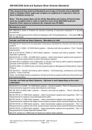
<strong>NSI</strong> <strong>SYSTEMS</strong> <strong>SILVER</strong> <strong>ACCESS</strong> <strong>CONTROL</strong><br />
<strong>MARKING</strong> <strong>TABLE</strong><br />
(based on ICP 30)<br />
Instructions<br />
1. This Marking Table should be used for inspection of Access Control systems.<br />
2. Deviations are to be entered on the Inspection Report by item letter, item number,<br />
and ICP 30 clause<br />
e.g. A(1) 5.3 Name of customer not stated 1 point<br />
NOTE: Points are awarded against the Marking Table item, not the individual<br />
deviation<br />
e.g.<br />
If there are three deviations under item E (cable installation), only 2 points are<br />
awarded against item E.<br />
This is an unpublished work, the copyright in which rests in <strong>NSI</strong>. All rights reserved. The<br />
information contained herein is the property of <strong>NSI</strong> and is supplied without liability for errors or<br />
omissions and no part may be reproduced, used or disclosed except as authorised by contract<br />
or other written permission. The copyright and the foregoing restriction on reproduction, use<br />
and disclosure extend to all the media in which this information may be embodied.<br />
ISF 449 - Issue 3 – February 2010<br />
1 of 5
<strong>NSI</strong> <strong>SYSTEMS</strong> <strong>SILVER</strong> <strong>ACCESS</strong> <strong>CONTROL</strong> SYSTEM <strong>MARKING</strong> <strong>TABLE</strong><br />
BASED ON ICP 30<br />
Item Check Points<br />
A Documentation 1<br />
B Ease of operation 1<br />
C Security features on CPU 1<br />
D Ease of access for maintenance of controls 1<br />
E Cable installation 2<br />
F Reader functions and indications 1<br />
G Location of readers 1<br />
H Details of batteries for active tokens 1<br />
I Door and turnstile fittings 1<br />
J Power requirements 2<br />
K Safety and security requirements 1<br />
L Back-up and maintenance facilities 1<br />
Access systems will be checked against the sections listed above. Detailed checks within<br />
each section are shown in the Marking Table attached.<br />
ISF 449 - Issue 3 – February 2010<br />
2 of 5
<strong>NSI</strong> <strong>SYSTEMS</strong> <strong>SILVER</strong> <strong>ACCESS</strong> <strong>CONTROL</strong> SYSTEM <strong>MARKING</strong> <strong>TABLE</strong> (ICP 30)<br />
A. Documentation<br />
REQUIREMENTS<br />
Does the documentation include the following:<br />
Systems Silver<br />
CoP Clause<br />
ICP 30<br />
1. Name and address of customer/or protected premises 5.3<br />
2. Full instructions for the operation of the system,<br />
including any relevant manufacturers literature<br />
3. The classification of the products relating it to the risk<br />
and the level of security that will be provided<br />
4. An accurate specification, logging facilities, location,<br />
alarms annunciation and type of all equipment<br />
5. The period of operation and/or the number of<br />
operations following a mains failure<br />
5.1/5.3<br />
5.3<br />
4.3/5.2/5.3<br />
5.2/5.3<br />
6. Records of commissioning tests 5.1<br />
7. For card systems a record of the supply volts and<br />
current to all parts of the system<br />
8. Is there a record of maintenance/service visits? Part 2 4.4/4.5<br />
9. Is there a Systems Silver certificate? Reg. 10<br />
B. Ease of Operation<br />
Have operators been suitably trained in the use of the system<br />
including any alarm monitoring<br />
C. Security Features of CPU<br />
Is the system protected against unauthorised interference, e.g.<br />
password level(s)<br />
D. Ease of Access for Maintenance of Controls<br />
1. Is there ease of access for maintenance? 4.3<br />
2. Is there adequate ventilation in the area of the CPU? 4.3<br />
3. Is the equipment free from environmental problems<br />
such as dust, vibration, electrical interference etc.?<br />
E. Cable Installation<br />
1. Is all cable installed within the controlled area and/or<br />
protected from accidental or willful damage?<br />
2. Does the cable size allow correct operation at the<br />
furthest reader?<br />
3. Are all connections in accordance with the current IEE<br />
Wiring Regulations?<br />
5.1<br />
5.2<br />
4.3<br />
4.3<br />
4.2.5.1<br />
4.2.5.2<br />
4.2.5.3<br />
ISF 449 - Issue 3 – February 2010<br />
3 of 5
E. Cable Installation (continued)<br />
4. Are cable joints made in suitable junction boxes using<br />
either wrapped, soldered, crimped or screw terminals?<br />
4.2.5.1<br />
5. Are overhead cables clear of any obstacles? 4.2.5.1/4.2.5.3<br />
6. Are cables run clear of interference from electrical<br />
contractors, microwave devices etc.?<br />
7. Are cables installed and supported to good working<br />
practice and correctly marked?<br />
8. Are all external junction boxes weatherproofed to IP 54<br />
or IP 65 if in a very exposed position?<br />
F. Reader Functions and Indications<br />
4.2.5.1<br />
4.2.5.1/4.2.5.3<br />
4.2/4.2.5.1<br />
4.2.5.3<br />
1. Is there an indication for access granted or denied? 4.2.2<br />
2. Are readers tamper proof and is a latching indication of<br />
tamper given?<br />
4.2.2<br />
3. If a variable release door timer is specified is it fitted? 4.2.2<br />
4. Does the furthest reader from the controller respond<br />
within 2 seconds following completion of the data entry?<br />
G. Location of Readers<br />
1. Are readers and associated wiring fitted to minimise the<br />
risk of vandalism, particularly if close to external perimeters?<br />
2. Do external readers meet the requirements of IP 54 or<br />
IP 65 if very exposed?<br />
3. Are readers located at convenient height of approx. 1.5<br />
m, preferably adjacent to the opening edge of the door?<br />
4. Are wired connections to readers concealed or given<br />
the appropriate mechanical protection, i.e. if the door release<br />
signal passes outside of the controlled area, metal conduit<br />
should be used?<br />
5. Are keyboards located to prevent illegal observations of<br />
the codes?<br />
H. Details of Batteries for Active Tokens<br />
Are the minimum battery life and operating range as specified<br />
on the manufacturers data sheet?<br />
I. Door and Turnstile Fittings<br />
4.2.2<br />
4.2.2<br />
4.2/4.2.5.3<br />
4.2.3<br />
4.2.2<br />
4.2.2/4.2.3<br />
4.2.5<br />
4.3<br />
4.2.1<br />
1. Are door catches and release mechanisms compatible? 4.2.3<br />
2. Have devices been fitted to minimise the effects of the<br />
environment, e.g. vibration, dust etc.?<br />
3. Is the physical strength of existing doors satisfactory<br />
after fitting locking mechanisms?<br />
4. Is the transfer of electrical connections onto doors by<br />
means of suitable, flexible cables in accordance with the<br />
manufacturer’s specification?<br />
4.2.3<br />
4.2.3<br />
4.2.3<br />
ISF 449 - Issue 3 – February 2010<br />
4 of 5
I. Door and Turnstile Fittings (continued)<br />
5. Do door closing devices close the door under normal<br />
circumstances including adverse air pressure?<br />
4.2.3<br />
6. Are doors a satisfactory fit in the frame? 4.2.3<br />
7. Are the hinges, frames and fixings adequate for the<br />
weight and proposed usage of the door?<br />
8. If a long operation for a door release is required is a<br />
continuous rated coil used?<br />
9. In the case of a complete power failure is there a key<br />
override to a critical door with the key kept in a safe place<br />
outside the controlled door?<br />
J. Power Requirements<br />
1. Does standby power, if fitted, function correctly and is<br />
the system memory protected by back-up storage?<br />
4.2.3<br />
4.2.3<br />
4.2.3<br />
4.2.4/4.3<br />
2. Are power supplies with the controlled area? 4.2.4<br />
3. Is the mains power permanently connected? 4.2.4<br />
4. Are extra low voltage cables kept separate from mains<br />
cables, particularly at entry points, and are they correctly<br />
insulated?<br />
5. Are all mains connections in accordance with the<br />
current issue of the IEE Wiring Regulations?<br />
K. Safety and Security Requirements<br />
1. Are all mains or high voltage powered equipments<br />
provided with warning labels, in accordance with IEE<br />
Regulations or Health & Safety Regulations?<br />
2. Does the system comply with the fire regulations and<br />
allow exit to personnel in an emergency?<br />
3. Does the specification clearly indicate whether the<br />
system is “fail safe”or “fail secure”?<br />
NOTE: If exit is granted via electrical means, fail safe may be<br />
mandatory to meet safety requirements.<br />
L. Back-up Maintenance Facilities<br />
1. Is there a current maintenance contract in force?<br />
2. Can the company provide call-out services in the time<br />
agreed in the contract?<br />
3. Can the installer offer hardware and software support to<br />
the system for at least 5 years?<br />
4.2.4<br />
4.2.5.3<br />
4.2.5.3<br />
4.2.5.3<br />
4.1/4.2.3<br />
Part 3:3.1<br />
3.3.2<br />
ISF 449 - Issue 3 – February 2010<br />
5 of 5