10292'04PD Abbe 60 Us.. - Bellingham and Stanley
10292'04PD Abbe 60 Us.. - Bellingham and Stanley
10292'04PD Abbe 60 Us.. - Bellingham and Stanley

Create successful ePaper yourself
Turn your PDF publications into a flip-book with our unique Google optimized e-Paper software.
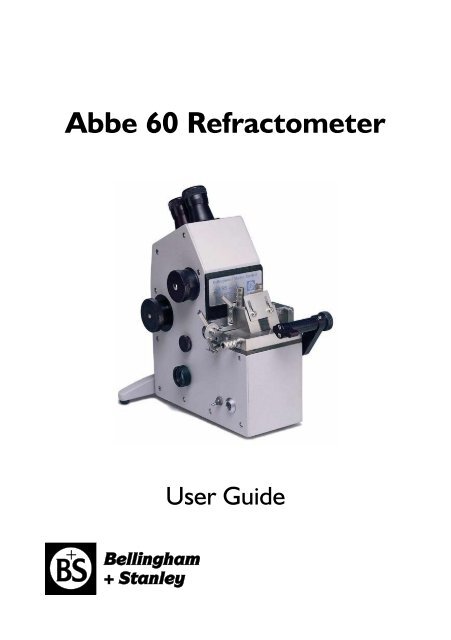
<strong>Abbe</strong> <strong>60</strong> Refractometer<br />
<strong>Us</strong>er Guide
DECLARATION OF CONFORMITY<br />
According to ISO/IEC Guide 22 <strong>and</strong> EN 45014<br />
Manufacturer's Name<br />
Manufacturer's Address<br />
<strong>Bellingham</strong> & <strong>Stanley</strong> Ltd.<br />
Longfield Road,<br />
Tunbridge Wells,<br />
Kent TN2 3EY<br />
United Kingdom<br />
declares that the product<br />
Product Name<br />
<strong>Abbe</strong> <strong>60</strong> Refractometer<br />
Model Number<br />
All<br />
is designed to conform to the following Product Specifications:<br />
Safety BS EN <strong>60</strong>950-1:2002<br />
EMC<br />
Emissions<br />
BS EN 61000-6-3:2007<br />
Immunity<br />
BS EN 61000-6-2:2007<br />
Emission for residential,<br />
commercial <strong>and</strong> lightindustrial<br />
environments<br />
Immunity for industrial<br />
environments<br />
Supplementary<br />
The product herewith is designed to comply with the<br />
requirements of the EMC Directive 89/336/EEC.<br />
This symbol is an internationally agreed indicator that the product<br />
bearing it should not be disposed of as general waste or garbage which<br />
might end up in l<strong>and</strong>fill sites, but should instead be sent for special<br />
processing <strong>and</strong>/or recycling in those countries where appropriate<br />
legislation <strong>and</strong> facilities are in place.<br />
This symbol indicates a caution or warning, please refer to the manual.
<strong>Abbe</strong> <strong>60</strong> <strong>Us</strong>er Guide (Eng)<br />
B+S Code : 10-292<br />
Issue 4D<br />
August 2013<br />
© Copyright <strong>Bellingham</strong> + <strong>Stanley</strong> Ltd. 2013<br />
Every effort has been made to ensure the accuracy of the contents of this manual. However, <strong>Bellingham</strong> +<br />
<strong>Stanley</strong> Ltd. can assume no responsibility for errors contained in the manual or their consequences.<br />
Printed in United Kingdom.<br />
<strong>Bellingham</strong> + <strong>Stanley</strong><br />
<strong>Bellingham</strong> + <strong>Stanley</strong><br />
Longfield Road,<br />
90 Horizon Drive<br />
Tunbridge Wells, Kent TN2 3EY Suwanee, GA 30024<br />
United Kingdom<br />
United States of America<br />
Main: +44 (0) 1892 500400 Main: (678) 804 5730<br />
Fax: +44 (0) 1892 543115 Fax: (678) 804 5729<br />
sales.bs.uk@xyleminc.com<br />
sales.bs.us@xyleminc.com<br />
Page 1
Installing the instrument<br />
Carefully remove all of the packing material. It is recommended that the box <strong>and</strong> other packing<br />
materials are retained so that, should the need arise, the refractometer can be safely returned to<br />
the manufacturer. Remove the cable tie that secures the upper prism box during transit. Open the<br />
upper prism box <strong>and</strong> remove packing material from between the two prisms.<br />
Contents list<br />
B+S code<br />
<strong>Abbe</strong> Refractometer<br />
see below for part number<br />
comprising:<br />
1 Operating Instructions 10-292<br />
1 Instruction manual CD-ROM 55-300<br />
1 Power supply 55-104<br />
1 Bottle of monobromonaphthalene 10-43<br />
1 Calibration test piece see below for part number<br />
1 Mains lead see below for part number<br />
- Calibration Tables see below for part number<br />
Part numbers<br />
<strong>Abbe</strong> refractometer part numbers<br />
Model Part number Calibration test piece Calibration Tables<br />
<strong>60</strong> / 95 10-03 Glass, 10-44 Not supplied<br />
<strong>60</strong> / DR 10-99 Glass, 10-44<br />
<strong>60</strong> / ED 10-04 Silica, 10-46 10-295<br />
<strong>60</strong> / LR 10-06 Silica, 10-46 10-297<br />
Power lead part numbers<br />
Description UK Version 230V Euro Version 230V US Version 110V<br />
Mains leads (for use with 55-104) 61-191 61-193 61-192<br />
Page 2
Positioning the system<br />
Place the instrument, <strong>and</strong> separate light source if used, on a flat <strong>and</strong> stable bench which is:<br />
• dry <strong>and</strong> indoors<br />
• away from draughty or hot equipment like fans or heaters<br />
• out of direct sunlight or strong ambient light<br />
• away from potential sources of interference, such as RFI generating equipment<br />
• within reach of a power point<br />
• not using a power circuit that also has large motors or noise generating equipment<br />
connected to it<br />
Mains connection<br />
The power supply adapter is supplied with a moulded mains cord <strong>and</strong> plug, to suit one of several<br />
socket types. For UK lead, replace fuse only with the type indicated on plug.<br />
Type Plug Style Mains cord wire colours<br />
Line<br />
(Phase)<br />
Neutral<br />
(Return)<br />
Earth<br />
(Ground)<br />
UK (230V) 13 Amp square pin to BS363/A Brown Blue Green / Yellow<br />
EU (230V) European Schuko plug25 Brown Blue Green / Yellow<br />
US (110V) 3 pin American plug Black White Green<br />
Power requirements<br />
Voltage<br />
Maximum load<br />
110 to 230V ~ ± 10%, 50 to <strong>60</strong> Hz<br />
less than 50 mA<br />
Power supply adapter<br />
RISK OF ELECTRIC SHOCK:<br />
• For electrical safety information, read the leaflet enclosed with the power supply.<br />
• For indoor use only.<br />
• Must be kept dry.<br />
• Disconnect the equipment from the mains supply before unplugging the mains lead<br />
from the power supply unit.<br />
• Do not open the power supply adapter. No user serviceable parts inside.<br />
WARNING:<br />
• For indoor use only.<br />
• Must be kept dry.<br />
• No user serviceable parts inside.<br />
• Do not open.<br />
• Do not cover, designed to operate with free air convection.<br />
• No cleaning required.<br />
Page 3
Instrument overview<br />
<strong>Abbe</strong> <strong>60</strong> refractometers can be used to measure the refractive index of liquid or solid samples for a<br />
wide range of applications.<br />
There are 2 versions of the instrument:<br />
Direct Reading models<br />
<strong>60</strong>/95 Range 1.300 to 1.535<br />
<strong>60</strong>/DR Range 1.300 to 1.740<br />
Sample values can be read directly from the scale graticule in either refractive index or %sucrose<br />
(°Brix).<br />
These models have a built-in adjustable L.E.D. light source at approximately 589nm wavelength.<br />
High Accuracy models<br />
<strong>60</strong>/ED Range 1.30 to 1.74<br />
<strong>60</strong>/LR Range 1.20 to 1.70<br />
The High Accuracy models have a scale graticule graduated in linear divisions. The sample readings<br />
must be converted to refractive index (or other scales such as Brix) using either a software program<br />
or conversion tables.<br />
A separate monochromatic light source is required; e.g. a Spectral Lamp Unit with a cadmium,<br />
mercury or sodium bulb.<br />
Page 4
Main parts & controls<br />
Dispersion drum<br />
(Direct Reading models)<br />
Micrometer drum<br />
Water nozzle<br />
Upper prism shutter<br />
Upper prism box<br />
Integral L.E.D. light source<br />
(Direct Reading models only)<br />
Lower prism box<br />
Water nozzle<br />
Toggle clamp<br />
Power switch<br />
(Fitted to early<br />
models only)<br />
Power<br />
connector<br />
Scale telescope<br />
Temperature display<br />
Control knob<br />
Calibration<br />
Adjustment<br />
cover<br />
Desiccator<br />
Page 5
The upper & lower prism boxes<br />
A liquid sample to be tested is placed on the measurement prism <strong>and</strong> the upper prism is clamped<br />
down onto it forming a thin layer of the sample. Light from the light source passes through upper<br />
prism, then is refracted through the sample layer <strong>and</strong> into the measurement prism.<br />
The upper prism box is held in place by a toggle clamp, which also forces the box up by a few<br />
millimetres when opening. The toggle clamp also prevents the upper prism box dropping directly<br />
onto the measurement prism <strong>and</strong> causing damage to the surface.<br />
The upper & lower prism boxes both incorporate water jackets, each with two hose connection<br />
nozzles. This enables the sample to be temperature controlled from a water circulator.<br />
Prism box toggle clamp<br />
Measurement prism<br />
Lower prism box<br />
Water nozzles<br />
Any deterioration of the surface condition of the measurement prism will limit the performance of<br />
the instrument <strong>and</strong> make accurate measurements difficult.<br />
It is important to keep the measurement prism in good condition.<br />
The temperature display module<br />
The current temperature of the measurement prism is continually monitored <strong>and</strong> shown on the<br />
display on the rear face of the instrument in degrees Celsius.<br />
Page 6
Direct Reading instruments only<br />
The Direct Reading instruments have an integral L.E.D. (light emitting diode) light source for sample<br />
illumination.<br />
L.E.D. light source<br />
L.E.D. arm adjustments<br />
A dispersion drum is fitted to Direct Reading instruments to enable colours other than yellow<br />
originating from the L.E.D (or more significantly, an alternative white light source) to be removed<br />
from the field view. This will sharpen the borderline <strong>and</strong> allow accurate setting against the<br />
crosswires.<br />
High Accuracy instruments only<br />
High Accuracy models are not fitted with an integral L.E.D. light source because a monochromatic<br />
light source, such as a sodium lamp, is required to achieve the measurement precision.<br />
A window <strong>and</strong> shutter are fitted in the lower prism box, which allows the instrument to be<br />
alternatively used in reflection, rather than transmission, mode. This is useful when reading dark<br />
samples. (See page 3-4 for more details)<br />
Lower prism box window<br />
Lower prism box window shutter<br />
• Turn the knob anticlockwise to close the shutter for transmission measurements<br />
• Turn the knob clockwise to open the shutter for reflection measurements<br />
Page 7
Initial setting up<br />
Power supply<br />
All <strong>Abbe</strong> <strong>60</strong> refractometers are supplied with an external power supply, which should be plugged<br />
into the sealed power connector on the side of the instrument.<br />
The power supply itself is connected to the mains supply by a moulded mains lead, which is also<br />
supplied with the instrument.<br />
Connect the mains lead to the mains supply <strong>and</strong> switch on the supply.<br />
Early models only, with serial numbers prior to A01051<br />
Switch the instrument on by pressing down the power switch, located next to the instrument<br />
power connector.<br />
Altering the focus of the telescopes<br />
To alter the focus of either of the telescopes, move the lens cap away <strong>and</strong> towards the main body<br />
of the instrument until the scale <strong>and</strong> the crosswires are well defined. To help the lens cap move,<br />
twist it whilst adjusting the focus.<br />
Below are examples of the views that you will get when looking down each of the telescopes (the<br />
scale view is that of a Direct Reading instrument).<br />
Scale view<br />
Field view<br />
Adjusting the upper prism box shutter<br />
The upper prism box shutter has two separate functions.<br />
The first is to control the amount of light from the light source that is passed through the sample;<br />
this is necessary to adjust the contrast between the light <strong>and</strong> dark parts of the borderline.<br />
The other use is to limit unwanted, ambient light entering the prism. If you are using the integral<br />
L.E.D. light source on a Direct Reading instrument, it is recommended that the shutter should<br />
initially be open about 2mm. This will restrict the amount of white light entering the sample. When<br />
using a spectral light source the shutter has a lesser effect, as the light source will be able to flood<br />
the sample with light.<br />
Page 8
Measuring a sample<br />
Setting the borderline<br />
Push the toggle down <strong>and</strong> raise the upper prism box. Clean the polished surfaces of the upper <strong>and</strong><br />
measurement prisms using distilled water with a soft tissue. Finish off by drying the prisms with soft<br />
tissues.<br />
Apply a few drops of sample to the centre of the measurement prism with a pipette. Lower the<br />
upper prism box <strong>and</strong> lift the toggle clamp to lock it onto the measurement prism. Any excess<br />
sample should be wiped away using soft tissues; this will improve the definition of the borderline.<br />
Look into the field telescope <strong>and</strong> rotate the control knob until the borderline (the<br />
point where the light <strong>and</strong> dark areas meet) comes into view.<br />
It should then be aligned with the centre of the cross hairs in<br />
the field telescope.<br />
To obtain the optimal borderline quality, both the light source position <strong>and</strong> the<br />
prism box shutter should be adjusted.<br />
Direct Reading models (<strong>Abbe</strong> <strong>60</strong>/95, <strong>60</strong>/DR)<br />
The L.E.D. light source has two adjustable joints, allowing the light to be easily positioned to<br />
provide the best borderline. To adjust a joint, turn the associated clamping knob anti-clockwise<br />
until it is loose enough to allow the joint to move. Make the adjustment <strong>and</strong> tighten the knob by<br />
turning it clockwise, whilst holding any adjustments in place.<br />
The L.E.D. should be positioned so that it illuminates just the bottom of the upper prism.<br />
The dispersion drum control knob should be adjusted to remove as much colour as possible from<br />
entering the field view. This will improve the borderline quality. The borderline might need to be<br />
re-aligned with the crosshairs after setting the dispersion drum.<br />
High Accuracy models (<strong>Abbe</strong> <strong>60</strong>/ED, <strong>60</strong>/LR)<br />
Close the lower prism box window shutter by turning the knob anticlockwise.<br />
Position the external light source directly in front of the <strong>Abbe</strong> <strong>and</strong> align the opening in the light<br />
source with the upper prism box. Next, adjust the height of the light source, so that all the upper<br />
prism box is well illuminated with the light.<br />
If the light source being used requires a filter, this should be slipped over the field telescope lens<br />
cap.<br />
Page 9
Determining the reading value<br />
Direct Reading models (<strong>60</strong>/95, <strong>60</strong>/DR)<br />
Look through the scale telescope <strong>and</strong> read the measurement value directly from the scale in either<br />
refractive index or %sucrose (°Brix).<br />
High Accuracy models (<strong>60</strong>/ED, <strong>60</strong>/LR)<br />
Turn the micrometer drum to the 0 position. Then whilst looking at the scale through the scale<br />
telescope, turn the micrometer drum until the previous scale division is straddled centrally by the<br />
two fiducial lines.<br />
The example shown would give a value through the scale telescope<br />
of 33.3.<br />
Next, read the value on the micrometer drum, this example being 4.3.<br />
The total scale reading will then be:<br />
The value through the scale telescope + the micrometer value divided by 100<br />
Example: 33.3 + 4.3 / 100 = 33.3 + 0.043 = 33.343<br />
Scale reading = 33.343<br />
The operator can then determine the refractive index from the scale reading by one of two<br />
methods:<br />
• The <strong>Abbe</strong> Utilities software<br />
• Calibration table<br />
Page 10
<strong>Us</strong>ing the <strong>Abbe</strong> Utilities software<br />
Every <strong>Abbe</strong> refractometer is supplied with an Instruction Manual CD (55-300), contained within this<br />
CD is a copy of the <strong>Abbe</strong> Utilities program, which runs on Microsoft Windows. It provides the<br />
ability to convert from <strong>Abbe</strong> scale reading to refractive index <strong>and</strong> other scales.<br />
Firstly, check that the <strong>Abbe</strong> Setup data<br />
matches that of your instrument <strong>and</strong> light<br />
source. If the settings are not correct, press<br />
<strong>and</strong> edit the values.<br />
To convert an <strong>Abbe</strong> scale reading into<br />
refractive index, place the cursor in the data<br />
entry box below ‘<strong>Abbe</strong>’, type the <strong>Abbe</strong><br />
scale value ‘17.243’ <strong>and</strong> press enter. The<br />
equivalent RI, Brix <strong>and</strong> selected UDS scale<br />
values will be shown in the relevant boxes.<br />
<strong>Us</strong>ing a Calibration Table<br />
Every High Accuracy instrument is supplied with a calibration table booklet for sodium D line,<br />
which will convert <strong>Abbe</strong> scale readings into refractive index. Below is an example for how the<br />
refractive index value for an <strong>Abbe</strong> scale reading of 17.243 is calculated, using calibration tables.<br />
Scale .00 ... .03 .04 .05<br />
17.1 1.46<strong>60</strong>4 ... 632 641 650<br />
17.2 1.46696 ... 724 733 743<br />
17.3 1.46789 ... 816 826 835<br />
First find the correct row in the table,<br />
which for the example would be 17.2.<br />
Now find the correct column in that<br />
row, e.g. 0.04. The column <strong>and</strong> row<br />
position would give the correct <strong>Abbe</strong><br />
scale reading for 17.24.<br />
To calculate the refractive index reading, take the RI value for 17.20, which is 1.46696 <strong>and</strong><br />
substitute the last 3 numbers for the 3 numbers found at 17.24 in the table, 733. This would make<br />
the reading 1.46733.<br />
Finally, use the third decimal place of the <strong>Abbe</strong> scale reading.<br />
Find the refractive index reading for the next column, in this case, 17.25, which would be 1.46743.<br />
Then calculate the RI from:<br />
Where:<br />
⎛ H − C ⎞<br />
A = ⎜ ⎟*<br />
D + C<br />
⎝ 10 ⎠<br />
⎛1.46743−1.46733⎞<br />
A = ⎜<br />
⎟*3+<br />
1.46733<br />
⎝ 10 ⎠<br />
A = 1.46736<br />
H=Next columns RI value=1.46743<br />
C=First columns RI value=1.46733<br />
D=Scale reading 3rd DP=3<br />
A=Actual RI<br />
Cleaning the prisms<br />
Page 11
With the measurement taken, the prism can now be cleaned. Samples should be removed from the<br />
prism surfaces as soon as practical after measurement. Leaving sample between the prisms for long<br />
periods, <strong>and</strong> allowing it to dry, can cause the two prisms to stick together.<br />
The sample should be removed from both prisms using a suitable solvent; distilled water or alcohol,<br />
depending upon whether the sample is water or oil based, <strong>and</strong> cleaning with tissue. The prisms<br />
should then be finally washed with distilled water or alcohol <strong>and</strong> dried with clean tissue.<br />
Note:<br />
When cleaning the prisms, please remember that excessive rubbing with abrasive tissues could<br />
scratch the prism surfaces. This would reduce the quality of the borderline <strong>and</strong> also cause sample<br />
contamination. B&S do not recommend the use of aggressive solvents such as acetone – always use<br />
alcohols or other non-aggressive solvents.<br />
Reflection mode (High Accuracy models only)<br />
If the sample layer is optically dense at the wavelength used, then insufficient light may not pass<br />
through it to provide a visible borderline. This problem can generally be overcome by using internal<br />
reflection of the light at the interface of the prism <strong>and</strong> sample.<br />
To use internal reflection<br />
• Slide down the “Upper prism shutter” to prevent light entering into the upper prism.<br />
• Open the “Lower prism box window shutter” by turning the knob clockwise as seen from<br />
the front of the instrument.<br />
• Adjust the light source to enter the “Lower prism box window.<br />
The borderline as seen in the field telescope will however be inverted, the darker part of the field<br />
being at the top. <strong>Us</strong>ually the contrast is not so good as with transmission mode but in general a<br />
sharp line can be obtained.<br />
Page 12
Calibrating the instrument<br />
The calibration of all <strong>Abbe</strong> <strong>60</strong> refractometers can be adjusted to accurately set the scale relative to<br />
a test piece with known refractive index. This adjustment should only need to be made at<br />
infrequent intervals, but it is recommended that the test piece be applied as a daily routine to check<br />
that all is in order <strong>and</strong> the instrument is reading correctly. Certainly check at each change of user<br />
since the setting position varies from one person to another.<br />
Checking the instrument with the test piece<br />
Apply two small drops of monobromonaphthalene contact liquid (supplied<br />
with the instrument, code no. 10-43) to the centre of the measurement<br />
prism, using a small wooden or plastic stick. The test piece should be<br />
placed polished side down onto the prism on top of the contact liquid.<br />
Take care when applying the test piece not to scratch the prism. The<br />
contact liquid should spread out under the test piece <strong>and</strong> cover the whole<br />
of the interface between the test piece <strong>and</strong> the prism.<br />
It is important to use the correct amount of contact liquid; there should be just sufficient to cover<br />
the interface but should not spread beyond the test pieces edges. The correct amount can only be<br />
found with experience.<br />
To check the test piece is applied correctly, see that it does not rock. If it does, remove the test<br />
piece <strong>and</strong> clean off the contact liquid; then re-apply as above.<br />
To remove a test piece from the prism, apply an alcohol-based solvent liberally around the test<br />
piece <strong>and</strong> allow it to “float” off of the prism surface with the minimum of sliding.<br />
Each test piece is identified by a serial number <strong>and</strong> is supplied with a Certificate of Precision<br />
specifying its actual refractive index.<br />
For Direct Reading models, the refractive index can be read from the scale <strong>and</strong> compared with the<br />
test piece value.<br />
For High Accuracy instruments, the correct <strong>Abbe</strong> scale reading for the silica test piece can be found<br />
on the front page of the Calibration Table supplied with the instrument. If the <strong>Abbe</strong> Utility<br />
software is used, press<br />
<strong>and</strong> the correct <strong>Abbe</strong> scale reading will be displayed.<br />
Page 13
Adjusting the instrument calibration<br />
Ensure that the borderline is accurately aligned with the cross wires in the field telescope. Unscrew<br />
<strong>and</strong> remove the Calibration Adjustment Cover.<br />
Direct Reading models (<strong>Abbe</strong> <strong>60</strong>/95, <strong>60</strong>/DR)<br />
Gently adjust the calibration screw using a large flat screw driver so that the correct reading is<br />
shown in the scale telescope.<br />
High Accuracy models (<strong>Abbe</strong> <strong>60</strong>/ED, <strong>60</strong>/LR)<br />
Set the micrometer drum to the last 2 decimal places of the scale reading for the test piece, when<br />
displayed to 3 decimal places. For example, if the scale reading should read 16.275 then the<br />
micrometer drum should be set to 7.5. If the scale reading should be 16.002 then the micrometer<br />
drum should be set to 0.2.<br />
Gently adjust the calibration screw using a large flat screw driver so that the correct value is in the<br />
middle of the two fiducial lines. If the scale reading should be 16.275, then the scale should read<br />
16.2, e.g. the scale marker for 16.2 should be straddled by the fiducial lines.<br />
All models<br />
Finally, always replace the Calibration Adjustment Cover<br />
Page 14
Temperature effects on the measurement<br />
Temperature correction of the refractometer<br />
If the instrument is used to take measurements at any temperature other than 20°C, then it will be<br />
necessary to apply a temperature correction to the scale reading. This is to compensate for the<br />
change of refractive index of the prism at the working temperature; the instrument being initially<br />
calibrated at 20°C.<br />
Direct Reading models<br />
<strong>Abbe</strong> <strong>60</strong>/95<br />
Measured Brix value 0 10 20 30 40 50 <strong>60</strong> 70 80 90<br />
Correction: °Brix/°C 0.005 0.005 0.005 0.004 0.004 0.004 0.003 0.003 0.003 0.003<br />
Measured Refractive index 1.30 to 1.535<br />
Correction: Refractive Index/°C 0.0000076<br />
<strong>Abbe</strong> <strong>60</strong>/DR<br />
Measured Brix value 0 10 20 30 40 50 <strong>60</strong> 70 80 90<br />
Correction: °Brix/°C 0.005 0.005 0.005 0.004 0.004 0.004 0.003 0.003 0.003 0.003<br />
Measured Refractive index 1.30 to 1.74<br />
Correction: Refractive Index/°C 0.0000078<br />
Examples: A <strong>60</strong>/95 gives a reading of 35.4°Brix at a temperature of 75°C<br />
(T – 20) x 0.004 = 55 x 0.004 = 0.22<br />
Scale reading of instrument = 35.4<br />
Corrected reading = 35.62<br />
A <strong>60</strong>/DR gives a reading of 1.4864 at a temperature of 70°C<br />
(T – 20) x 0.0000078 = 50 x 0.0000078 = 0.00039<br />
Scale reading of instrument = 1.4864<br />
Corrected reading = 1.48679<br />
High Accuracy models (<strong>Abbe</strong> <strong>60</strong>/ED, <strong>60</strong>/LR)<br />
<strong>Us</strong>ing the <strong>Abbe</strong> Utilities software<br />
Enter the measurement temperature in <strong>Abbe</strong> Setup <strong>and</strong> the correction will be carried out<br />
automatically.<br />
<strong>Us</strong>ing a Calibration Table<br />
Details for correction with temperature are shown at the end of the tables.<br />
Page 15
Temperature correction of the sample<br />
The refractive index of all samples will vary with temperature. If it is required to know the<br />
refractive index of the sample at 20°C, then either the instrument must be controlled at 20°C, as<br />
described below, or a correction value for the sample must be added to the scale reading.<br />
The correction value will vary considerably with the type of sample. Glass samples have a low<br />
temperature coefficient, water based products are higher <strong>and</strong> oils <strong>and</strong> chemicals generally greatest.<br />
Typical (<strong>and</strong> very approximate) values are:<br />
Sample<br />
Temperature coefficient: Change in index / °Celsius<br />
Glass +0.00001<br />
Water<br />
-0.00010 (-0.07°Brix)<br />
50% sucrose sample (50°Brix) -0.00017 (-0.08°Brix)<br />
Edible oil -0.00040<br />
Correction values for sucrose solutions measured on the Brix (% Sucrose) scale are shown in the<br />
table below. The correction values should be added to the scale reading.<br />
Page 16
Scale reading °Brix<br />
0 5 10 15 20 25 30 35 40 45 50 55 <strong>60</strong> 65 70 75 80 85<br />
15 -0.29 -0.30 -0.32 -0.33 -0.34 -0.35 -0.36 -0.37 -0.37 -0.38 -0.38 -0.38 -0.38 -0.38 -0.38 -0.38 -0.37 -0.37<br />
16 -0.24 -0.25 -0.26 -0.27 -0.28 -0.28 -0.29 -0.30 -0.30 -0.30 -0.31 -0.31 -0.31 -0.31 -0.31 -0.30 -0.30 -0.30<br />
17 -0.18 -0.19 -0.20 -0.20 -0.21 -0.21 -0.22 -0.22 -0.23 -0.23 -0.23 -0.23 -0.23 -0.23 -0.23 -0.23 -0.23 -0.22<br />
18 -0.12 -0.13 -0.13 -0.14 -0.14 -0.14 -0.15 -0.15 -0.15 -0.15 -0.15 -0.15 -0.15 -0.15 -0.15 -0.15 -0.15 -0.15<br />
19 -0.06 -0.06 -0.07 -0.07 -0.07 -0.07 -0.07 -0.08 -0.08 -0.08 -0.08 -0.08 -0.08 -0.08 -0.08 -0.08 -0.08 -0.07<br />
20 0.00 0.00 0.00 0.00 0.00 0.00 0.00 0.00 0.00 0.00 0.00 0.00 0.00 0.00 0.00 0.00 0.00 0.00<br />
21 0.06 0.07 0.07 0.07 0.07 0.07 0.08 0.08 0.08 0.08 0.08 0.08 0.08 0.08 0.08 0.08 0.08 0.07<br />
22 0.13 0.14 0.14 0.14 0.15 0.15 0.15 0.15 0.16 0.16 0.16 0.16 0.16 0.16 0.15 0.15 0.15 0.15<br />
23 0.20 0.21 0.21 0.22 0.22 0.23 0.23 0.23 0.23 0.24 0.24 0.24 0.24 0.23 0.23 0.23 0.23 0.22<br />
24 0.27 0.28 0.29 0.29 0.30 0.30 0.31 0.31 0.31 0.32 0.32 0.32 0.32 0.31 0.31 0.31 0.30 0.30<br />
Temperature °Celsius<br />
25 0.34 0.35 0.36 0.37 0.38 0.38 0.39 0.39 0.40 0.40 0.40 0.40 0.40 0.39 0.39 0.38 0.38 0.37<br />
26 0.42 0.43 0.44 0.45 0.46 0.46 0.47 0.47 0.48 0.48 0.48 0.48 0.48 0.47 0.47 0.46 0.46 0.45<br />
27 0.50 0.51 0.52 0.53 0.54 0.55 0.55 0.56 0.56 0.56 0.56 0.56 0.56 0.55 0.55 0.54 0.53 0.52<br />
28 0.58 0.59 0.<strong>60</strong> 0.61 0.62 0.63 0.64 0.64 0.64 0.65 0.65 0.64 0.64 0.63 0.63 0.62 0.61 0.<strong>60</strong><br />
29 0.66 0.67 0.68 0.70 0.71 0.71 0.72 0.73 0.73 0.73 0.73 0.73 0.72 0.72 0.71 0.70 0.69 0.67<br />
30 0.74 0.76 0.77 0.78 0.79 0.80 0.81 0.81 0.82 0.82 0.81 0.81 0.80 0.80 0.79 0.78 0.76 0.75<br />
31 0.83 0.84 0.85 0.87 0.88 0.89 0.89 0.90 0.90 0.90 0.90 0.89 0.89 0.88 0.87 0.86 0.84 0.82<br />
32 0.92 0.93 0.94 0.96 0.97 0.98 0.98 0.99 0.99 0.99 0.99 0.98 0.97 0.96 0.95 0.93 0.92 0.90<br />
33 1.01 1.02 1.03 1.05 1.06 1.07 1.07 1.08 1.08 1.08 1.07 1.07 1.06 1.04 1.03 1.01 1.00 0.98<br />
34 1.10 1.11 1.13 1.14 1.15 1.16 1.16 1.17 1.17 1.16 1.16 1.15 1.14 1.13 1.11 1.09 1.07 1.05<br />
35 1.19 1.21 1.22 1.23 1.24 1.25 1.25 1.26 1.26 1.25 1.25 1.24 1.23 1.21 1.19 1.17 1.15 1.13<br />
36 1.29 1.30 1.31 1.33 1.34 1.34 1.35 1.35 1.35 1.34 1.34 1.33 1.31 1.29 1.28 1.25 1.23 1.20<br />
37 1.39 1.40 1.41 1.42 1.43 1.44 1.44 1.44 1.44 1.43 1.43 1.41 1.40 1.38 1.36 1.33 1.31 1.28<br />
38 1.49 1.50 1.51 1.52 1.53 1.53 1.54 1.54 1.53 1.53 1.52 1.50 1.48 1.46 1.44 1.42 1.39 1.36<br />
39 1.59 1.<strong>60</strong> 1.61 1.62 1.63 1.63 1.63 1.63 1.63 1.62 1.61 1.59 1.57 1.55 1.52 1.50 1.47 1.43<br />
40 1.69 1.70 1.71 1.72 1.73 1.73 1.73 1.73 1.72 1.71 1.70 1.68 1.66 1.63 1.61 1.58 1.54 1.51<br />
Example:<br />
A <strong>60</strong>/95 gives a reading of 35.4° Brix at a temperature of 32° C<br />
Scale reading of instrument = 35.4<br />
Correction = 0.99<br />
Equivalent value at 20°C = 36.39<br />
Page 17
Temperature control from a circulator<br />
Both the fixed <strong>and</strong> hinged prism boxes are fitted with nozzles for water circulation in order to<br />
maintain the prisms <strong>and</strong> sample at known temperatures.<br />
By controlling the instrument to a constant temperature, the time necessary for the instrument to<br />
stabilise after applying a sample to the prism will be minimised <strong>and</strong> measurement conditions will be<br />
optimised for high accuracy work.<br />
If it is practical to control the instrument temperature to 20ºC, the corrections for the instrument<br />
<strong>and</strong> the sample detailed above will not be required.<br />
It is recommended that the two boxes are connected in series as follows.<br />
Incoming water should be fed into the left<br />
h<strong>and</strong> side of the main body, when viewed<br />
from behind. The water will exit through<br />
the right side of the main body. A 45cm<br />
long pipe should be connected to this<br />
nozzle <strong>and</strong> connected to the right h<strong>and</strong><br />
nozzle of the upper prism box. A pipe on<br />
the left nozzle on the upper prism box will<br />
return the water back to the circulator.<br />
With the instrument set-up as above, the<br />
<strong>Abbe</strong> will have both the water connections<br />
to the water bath on the left h<strong>and</strong> side,<br />
when viewed from behind. It is advisable<br />
to secure the pipes to the nozzles with<br />
hose clips. (The photograph shows the pipes without clips for clarity).<br />
Page 18
Measurement techniques<br />
Sample application<br />
Liquid samples<br />
It is recommended that liquid samples be transferred to the prism surface using a pipette rather<br />
than a stirring rod or pouring directly from a beaker. After taking up the sample, any drips adhering<br />
to the outside of the pipette should be wiped off then discharge a few drops from the pipette<br />
directly onto the prism surface <strong>and</strong> close the prism box. This is of considerable importance when<br />
taking concentration measurements since thin films adhering to a stirring rod <strong>and</strong> exposed to the<br />
atmosphere can evaporate solvent rapidly when moved through the air, giving rise to errors in<br />
measurement.<br />
Solid Samples<br />
These are applied in the same manner as the test piece using a contact liquid. A surface must be<br />
prepared, polished as flat as possible <strong>and</strong> placed on the prism surface with the hinged prism opened<br />
out of the way. If the solid has an index higher than 1.65, methylene iodide can be used as a contact<br />
liquid (B&S code 10-61) in place of monobromonaphthalene which can only be used up to this limit.<br />
Thin Films<br />
Results may be obtained on most thin films but here a technique must be evolved, determined by<br />
the material <strong>and</strong> conditions.<br />
Direct Application (Reflection mode: High Accuracy models only)<br />
Soft plastics <strong>and</strong> rubbery materials may be cured in a press between thin sheets of aluminium foil<br />
<strong>and</strong> reduced to a thickness of about 0.25mm. After preparation ensure that the prism surface is<br />
clean, strip off the foil on one side of the film <strong>and</strong> apply the exposed surface directly to the prism<br />
using no contact liquid.<br />
Indirect Application (Reflection mode: High Accuracy models only)<br />
Resins <strong>and</strong> other low melting point solids are best prepared by melting them onto a thin glass<br />
substrate (B&S code 10-59). After hardening, the substrate should be placed on the prism surface<br />
with a contact liquid with the coated surface uppermost. Two borderlines will appear, one due to<br />
the sample, the other due to the substrate which may be previously found <strong>and</strong> ignored. It is<br />
essential that the refractive index of the substrate should be greater than that of the sample.<br />
Dark samples (Reflection mode: High Accuracy models only)<br />
With certain materials of a non-transparent nature, such as thick oils, tar, marzipan etc., too much<br />
light may be absorbed in the sample film or be so scattered that definition is lost. In these cases, the<br />
trouble can generally be overcome by using reflection mode.<br />
Page 19
Accessories<br />
Volatile Liquid Cell<br />
This comprises a rectangular glass block, with one<br />
side hollowed out to form a cavity. Two holes pass<br />
between the cavity <strong>and</strong> the opposite face of the<br />
block.<br />
To use the cell, first ensure that the prism surface<br />
<strong>and</strong> the cavity face of the block are clean.<br />
Place the block, cavity down on the prism surface,<br />
<strong>and</strong> by means of a syringe, introduce sample into the<br />
cavity via the end filling port, leaving the central port<br />
clear for the escape of air. Fill the cavity <strong>and</strong> the<br />
filling ports to the top face of the block. After<br />
removing the syringe, close the filling ports by laying<br />
the thin plate over the top surface. The sample is<br />
now completely isolated from the atmosphere <strong>and</strong> will not be subject to evaporation.<br />
The cell capacity is in the region of 0.3 ml <strong>and</strong> this may be saved after measurement by drawing<br />
back into the syringe or lost by lifting the cell from the prism face for cleaning <strong>and</strong> drying.<br />
Divided Cell for differential measurements<br />
This is a circular cell with a dividing partition<br />
providing two sample compartments of semicircular<br />
form.<br />
Before use, it is necessary to clean the prism surface<br />
<strong>and</strong> the base disc of the cell. Place a small drop of<br />
contact liquid in the centre of the prism surface, then<br />
place the cell in position on top of the prism with the<br />
partition parallel to the sides of the prism <strong>and</strong><br />
central.<br />
Sample <strong>and</strong> reference are placed in the separate<br />
compartments <strong>and</strong> the control knob turned to bring<br />
the borderlines into view. The borderline due to<br />
each half of the cell occupies about two thirds of the<br />
field, thus extending sufficiently across the cross line for a setting to be made. The two may be<br />
compared accurately one against the other <strong>and</strong>, since they are in the same cell, under identical<br />
conditions, there is little risk of error due to temperature. It should be noted that, when observed<br />
in the field of view, the borderline to the left side arises from the sample on the right side of the<br />
partition <strong>and</strong> vice versa. This is due to the optical system within the instrument causing a reversal.<br />
Page 20
Funnel Flowcell<br />
Attaching the flowcell to the prism box.<br />
• Remove the two hexagon headed bolts securing<br />
the prism box hinge to the lower prism box <strong>and</strong><br />
completely remove the upper prism box.<br />
• Remove the two countersunk screws from either<br />
side of the toggle fastener <strong>and</strong> detach fastener.<br />
• Fit two angle brackets provided with the flow-cell<br />
to either side of the prism plate using the screws<br />
provided with the flowcell.<br />
• Check that the silicon rubber gasket is fitted in the<br />
flowcell with the rectangular aperture allowing<br />
unrestricted flow through the two inlet <strong>and</strong> outlet<br />
holes.<br />
• Fit the flowcell to the brackets, tightening the two<br />
knurled screws together to ensure that the<br />
flowcell sits parallel to the prism plate <strong>and</strong> the seal<br />
is uniformly compressed.<br />
Filling the flowcell<br />
The cell is provided with a filling funnel <strong>and</strong> a drain tube with antisyphon tube. This prevents the cell<br />
being drained by syphonic action in use. Place an empty beaker below the drain tube <strong>and</strong> pour in<br />
about 50 ml of distilled water into the funnel. Check for any leaks around the base of the flow cell.<br />
If any appear, check the tightening of the clamp screws <strong>and</strong>, if necessary, remove the cell <strong>and</strong><br />
reseat.<br />
The light source must be critically adjusted for the flow<br />
cell since the aperture is restricted <strong>and</strong> it is essential that<br />
the source is in the correct position. There is a recessed<br />
window for the admission of illumination between the<br />
two water jacket nipples. The light source must be<br />
adjusted to the same height as this aperture.<br />
The control knob is now used to set the scale to the<br />
correct reading for water, taking the temperature into<br />
account (1.3330 at 20°C). The borderline will be<br />
appear as an illuminated b<strong>and</strong> across the crosswires. It is the lower edge of the b<strong>and</strong> that is of<br />
importance. (Direct Reading models only: any colour at the edges of the b<strong>and</strong> should be cleared by<br />
rotating the dispersion control.) The upper edge of the illuminated b<strong>and</strong> is formed by a cut off by<br />
the cell entrance aperture <strong>and</strong> is thus out of focus <strong>and</strong> may be diffused. The lower edge, however,<br />
should be sharply defined <strong>and</strong> free from colour <strong>and</strong> is to be used in all measurements.<br />
It is possible that the lower (borderline) edge is not in coincidence with the crosswire intersection,<br />
this being due to a physical displacement of the prism plate caused by the pressure of the flow cell.<br />
This is of no consequence <strong>and</strong> only requires an adjustment to the zero as detailed in Section 3.<br />
Care must be taken in the use of the flow cell to avoid air pockets becoming trapped in the<br />
chamber. If this occurs, impairing definition, the instrument should be slightly inclined to attract the<br />
Page 21
ubble towards the rear end <strong>and</strong> flushed out with the addition of more sample.<br />
The number of flushes of the chamber between samples will depend upon the nature of the sample,<br />
<strong>and</strong> the difference in index between successive samples. It will be quickly established how much<br />
sample is required. For a start, the chamber should be flushed a number of times using about 15 ml<br />
each time. A reading should be taken between each flushing. When no change occurs between two<br />
such readings, it is an indication that flushing is adequate. Obviously, the greater the difference in<br />
refractive index between two samples, the greater the quantity required for flushing.<br />
<strong>Us</strong>ing filters<br />
Two types of filter are available, a Polarising Filter <strong>and</strong> a Spectral Line Filter. Both are mounted in a<br />
cap which fits over the field telescope.<br />
Polarising (Bi-Refringent) filter<br />
A polarising filter can be used on both the Direct Reading <strong>and</strong> High Accuracy models for the<br />
examination of bi-refringent materials. Rotation of the cap on top of the field telescope eyepiece<br />
will bring each borderline into prominence in turn <strong>and</strong> is a useful accessory particularly if the<br />
separation makes accurate settings difficult.<br />
Spectral filters<br />
<strong>Bellingham</strong> + <strong>Stanley</strong> can also supply filters which will pass a specific wavelength of light. These can<br />
be used on the High Accuracy models to isolate readings with specific wavelengths from, typically, a<br />
mercury or cadmium lamp.<br />
Page 22
Spares <strong>and</strong> accessories<br />
Power supplies<br />
55-104 Power supply 110 to 230V ~ ±10% 50 to <strong>60</strong>Hz<br />
61-191 UK mains lead (for use with 55-104)<br />
61-193 Euro mains lead (for use with 55-104)<br />
61-192 US mains lead (for use with 55-104)<br />
Cells<br />
10-41 Stainless steel funnel flow cell for repetitive sampling<br />
10-80 Silicon rubber flow cell gasket<br />
10-42 Volatile liquid cell<br />
10-58 Divided cell for differential measurements<br />
10-59 Glass substrate for resin samples<br />
Contact liquid<br />
10-43 Contact liquid (monobromonaphthalene) for test plates <strong>and</strong> solid<br />
samples with RI up to 1.65. Quantity 6 ml.<br />
10-61 Contact liquid (methylene iodide) for test plates <strong>and</strong> solid samples with<br />
RI up to 1.74. Quantity 3 ml.<br />
Eye piece filters<br />
10-69 Spectral filter eyecap (manufactured to order)<br />
10-49 Polarising eyecap for bi-refringent samples<br />
Test pieces<br />
10-44 Glass test plate with RI approximately 1.5222<br />
10-46 Silica test plate RI 1.45839 (traceable)<br />
Page 23
External light sources<br />
59-01 Free st<strong>and</strong>ing sodium lamp outfit 190/250v AC, 50/<strong>60</strong> Hz<br />
59-06 Free st<strong>and</strong>ing sodium lamp outfit 100/130v AC, 50/<strong>60</strong> Hz<br />
59-50 Spare sodium bulb (for use with 59-01 <strong>and</strong> 59-06)<br />
59-20 Free st<strong>and</strong>ing spectral lamp outfit 190/250v AC, 50/<strong>60</strong> Hz<br />
59-25 Free st<strong>and</strong>ing spectral lamp outfit 100/130v AC, 50/<strong>60</strong> Hz<br />
59-37 Cadmium lamp (for use with 59-20 <strong>and</strong> 59-25)<br />
59-33 Mercury lamp (for use with 59-20 <strong>and</strong> 59-25)<br />
59-31 Sodium lamp (for use with 59-20 <strong>and</strong> 59-25)<br />
59-39 Helium lamp (for use with 59-20 <strong>and</strong> 59-25)<br />
Miscellaneous<br />
55-300 Instruction Manual CD containing <strong>Abbe</strong> Utilities software<br />
10-292 Instruction manual (English)<br />
10-293 Instruction manual (Spanish)<br />
10-294 Instruction manual (French)<br />
10-299 Instruction manual (German)<br />
Page 24