SFRA Transformer Coil Manufacturing Quality
SFRA Transformer Coil Manufacturing Quality
SFRA Transformer Coil Manufacturing Quality

Create successful ePaper yourself
Turn your PDF publications into a flip-book with our unique Google optimized e-Paper software.
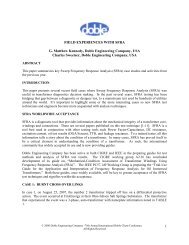
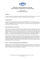
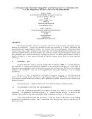
<strong>SFRA</strong> A TOOL TO ENSURE TRANSFORMER COIL MANUFACTURING<br />
QUALITY<br />
ABSTRACT<br />
Arun D Yargole<br />
Doble Engineering (India)<br />
Manufacturers of medium and large capacity transformers when under time / cost pressure tend to make some<br />
manufacturing / design variations. The variances are generally noticed after the manufacturing tests are conducted<br />
and only when compared to sister units. Recently, for a couple of cases, deviations were noticed in three sister<br />
single phase units having identical technical data. This change was seen only after comparing <strong>SFRA</strong> results. It is<br />
known that <strong>SFRA</strong> can be used as an effective tool by manufacturing to improve quality. The author suggests having<br />
variant (hardware / software) that can check the ‘wound coils’ during manufacturing stage itself. The idea is to<br />
allow the manufacturer to arrest the problem before the assembly is completed. The buyer then has the advantage of<br />
getting comparable sister units.<br />
INTRODUCTION<br />
Utility customers buy multiple units of transformers or reactors of same specifications. It is expected that they will<br />
be built with same design and manufacturing process hence are deemed to be sister units. Ideally they would be<br />
twin units.<br />
A few cases have shown that the above is not true always. Changes/deviations are made either in design or<br />
manufacturing. This was observed while analysis of the <strong>SFRA</strong> signatures of the sister units. Though we assume<br />
that the deviations taken are genuine and only for good, there is a concern as those deviations are generally not<br />
reported to the customer utilities.<br />
Probably it is because at present there is no test procedure to detect such deviations. Normally, all the units pass the<br />
tests stipulated in standards showing that the units that are manufactured will perform well on field. Questions then<br />
arise, why the deviations are taken and why they are not reported to the customers?<br />
The reality is even though the utilities come to know about this after proper analysis of frequency response, they<br />
have no choice but to commission these units as they are already installed on site and is too late. Utilities are<br />
observing such deviations frequently from some manufacturers.<br />
OBJECTIVE<br />
Since such deviations are taking place without the knowledge of the customer, it becomes a necessity that these<br />
should be arrested at manufacturing stage itself. Unless this practice becomes a part of a specification it would be<br />
difficult to arrest such anomalies. <strong>SFRA</strong> is well known tool to detect such anomalies in the transformer windings<br />
and core coil assemblies.<br />
This document suggests that purchasers of transformers may require the use of <strong>SFRA</strong> to ensure quality of their<br />
transformers. Clauses within their specifications can require <strong>SFRA</strong> comparisons for acceptance of their<br />
transformers. The <strong>SFRA</strong> tool may be used in the manufacturing process for comparison of signatures of windings,<br />
core coil assemblies and finished sister units.<br />
© 2011 Doble Engineering Company -78 th Annual International Doble Client Conference<br />
All Rights Reserved
DEVIATIONS ARE COMPROMISES<br />
Designers design the transformer for Guaranteed Technical Specifications {GTS} as specified by the utilities along<br />
with other features or customized solutions. Major guaranteed technical specifications that govern the material cost<br />
of the transformers are No-load losses, Full load Losses, %Impedance, Voltage factor, Voltage ratings, Number of<br />
taps, type of LTCs, in some cases height of the transformers, etc.<br />
In a competitive bidding situation, designers take a chance and commit all of above. This affects cost optimization<br />
on manufacturing. It then becomes a tough task for design and manufacturing teams. Cost and quality in such cases<br />
do not go hand in hand. If manufacturers have been awarded multiple units of same Guaranteed Technical<br />
specifications “GTS” the designers take a challenge to balance out cost in complete tender of multiple sister units<br />
while assuring the GTS.<br />
Assuring the GTS does not always mean that the product will work reliably on field. There are tests listed in various<br />
standards that cover the quality assurance from materials to final product. These tests generally ensure that the<br />
transformers are manufactured with good materials and in well defined processes that have been evolved over a<br />
period. However they are not able to detect the manufacturing variations if any between the multiple units of same<br />
specifications or we can call sister transformers.<br />
Such manufacturing deviations were noticed while analyzing the <strong>SFRA</strong> results of two utilities but when they were<br />
detected it was too late. <strong>Transformer</strong>s were already installed and awaiting clearance for commissioning. Utilities<br />
were not having any choice but to accept for completing the project.<br />
<strong>SFRA</strong> AND TRANSFORMER<br />
A recap of the designer’s challanges in transformer design.-<br />
There is a definite and well established relationship between response signature, geometry of transformers and<br />
physical properties of transformers.<br />
Resonating impedances seen in response are governed by a complex L-C-R circuits that covers multiple small<br />
circuits of intrinsic capacitances and self/mutual inductances. While self/mutual inductances “L” are governed<br />
mainly by number of turns, inner and outer radius of windings, height of the winding, the capacitances “C” are<br />
governed by area of conductor, thickness of insulation over the conductor for capacitor elements within a disc in<br />
disc type windings. There are multiple capacitive localized circuits within discs, within multiple discs, between<br />
winding and ground and in between windings. It’s very complex. In short L-C-R components are decided by the<br />
dimensions and physical properties of insulation material.<br />
Designers decide these dimensions for optimized design by using few main electrical parameters such as volts-perturn,<br />
flux density, current density, voltage stress (kV/mm) etc. These main parameters decide the performance<br />
parameters of the transformer such as winding losses, short circuit impedance, temperature rise, margin over high<br />
voltage withstand capability etc. Further they also control the dimension and weight of the transformer. Proper<br />
selection of above electrical parameters gives an optimized product.<br />
© 2011 Doble Engineering Company - 78 th Annual International Conference of Doble Clients<br />
All Rights Reserved<br />
2-8
To illustrate this let us go through a typical small exercise matrix as mentioned in Table 1.<br />
Table 1<br />
Complexity in Design of <strong>Transformer</strong> to Match GTS<br />
Parameters<br />
Effects<br />
Volts / turn for<br />
a fixed flux<br />
density<br />
maximum<br />
allowed by<br />
GTS<br />
Current<br />
density<br />
Voltage<br />
stress<br />
Weight of<br />
copper<br />
Weight of<br />
core<br />
Impedance<br />
Losses and<br />
temperature<br />
rise<br />
- - <br />
- - <br />
- <br />
- <br />
- or <br />
or <br />
Actually it’s very complex and that’s why designers use software tools<br />
Table 1 is based on basic design principles and indicates clearly the challenges faced by the designer. This further<br />
becomes more complicated while designing for customized requirements. This technology is well known to all<br />
established manufacturers and there could be hardly any variations with different manufacturers while handling<br />
these complex parameter matrices. Competition makes manufacturers to build some innovative ideas or design<br />
compromises.<br />
With designs once frozen, it is expected that the multiple units of same specification (true sister transformers) shall<br />
be manufactured and processed identically. <strong>Transformer</strong>s made this way can be called sister transformers. Typical<br />
responses of 13 sister transformers are given in Figure 1 below.<br />
Comparison of 13 Sister <strong>Transformer</strong>s and Their Correlation Coefficients<br />
Rating-29MVA, 220 / 3 kV / 11kV<br />
Figure 1<br />
© 2011 Doble Engineering Company - 78 th Annual International Conference of Doble Clients<br />
All Rights Reserved<br />
3-8
<strong>SFRA</strong> A TOOL TO CONTROL QUALITY<br />
Figure 1 indicates the manufacturing quality of 13 transformers with regard to their mechanical structure. Minor<br />
variations in responses seen are due to manufacturing tolerances and values of Correlation Coefficients indicate the<br />
level of tolerances. Normally, for good quality transformers these will be close tolerances and any anomaly<br />
observed while comparison can easily be attributed to the manufacturing change or design change.<br />
Once designs are frozen for meeting GTS and other customized requirements the mechanical dimensions get frozen<br />
with tolerances for coils and core of transformer. Tolerances for other structural components of transformers such<br />
as, core frame, tap leads, winding conductors, LTC chamber/s, tie-rods, barriers, end insulation etc. are also<br />
finalized. Once they are frozen for all sister units, the dimensions are not expected to change beyond the limits<br />
specified by the tolerances.<br />
Here comes the role of <strong>Quality</strong> Assurance team to check and keep them in control but at times there are deficiencies<br />
and they are invisible to the customers. The manufacturing deviations listed in two cases below could have been<br />
arrested if the QA would have functioned efficiently. They could have been arrested if they would have been visible<br />
to the customer while in manufacturing stage.<br />
<strong>SFRA</strong> then can be used here to endorse this QA function if used for coils, core coil assembly and finished<br />
transformer at appropriate stages.<br />
Normally when coils get manufactured with prescribed tolerances it is expected that the response comparison<br />
between them shall be very close. To supplement visual comparison, we can decide standard correlation<br />
coefficients at different bands of frequencies by generating and studying data by using statistical analysis.<br />
CASES SUGGESTING PUTTING <strong>SFRA</strong> TOOL IN QUALITY PROCESS<br />
Case 1: Three Single Phase Sister Auto <strong>Transformer</strong>s. {167MVA, 4400 kV/220 kV/33 kV ICT}<br />
This case was referred to Doble because the customer has seen some variations between the <strong>SFRA</strong> results of three<br />
sister transformers at factory and the site. These are three single phase auto transformers. When compared there<br />
was no deviation found between the factory signatures and site signatures of individual transformers.<br />
Additional Findings<br />
Though the signatures of individual transformers were matching well between the factory and the site, one of them<br />
was not matching with other two. This was not expected as they were supposed to be very identical being true sister<br />
transformers. Refer to Figure 2.<br />
#3<br />
#1<br />
#2<br />
Comparison of Partial Winding of Three Sister <strong>Transformer</strong>s<br />
Figure 2<br />
© 2011 Doble Engineering Company - 78 th Annual International Conference of Doble Clients<br />
All Rights Reserved<br />
4-8
In Figure 2 above, they being sister transformers the matching of signatures between them was expected but<br />
transformer S/N #2 stood differently.<br />
Now there was deviation taken during manufacture of #2. Additional care was taken for impulse voltage<br />
distribution but probably this was not informed to the customer. After receiving our report, utility got wiser and<br />
investigated further. Manufacturer has accepted and disclosed the deviation in design.<br />
This change got disclosed very late when the transformers were ready in the field waiting to be commissioned. The<br />
utility had no choice but to investigate and accept. This could have affected their commissioning schedule.<br />
These are some hypotheses for what could have happened<br />
1. Manufacturer was cautious and selected a design for better impulse voltage distribution in the windings.<br />
This could have been the first unit. Knowing the better results and margin for optimization thereon,<br />
designer changed the design for remaining units.<br />
2. Manufacturer made the #2 design for type test<br />
3. Manufacturer optimized other two designs for cost savings.<br />
4. Under pressure of delivery the design deviations are taken.<br />
Case 2: Two three phase sister reactors {63MVAr 400 kV}<br />
This case was referred to Doble because the customer noticed the deviations in Y phase while phase-to-phase<br />
signature comparison of a three phase reactor. Refer to Figure 3. To justify the deviation a support of Y phase of<br />
sister unit was taken as explained in Figure 4.<br />
Additional Findings<br />
The above was not acceptable as while further investigations it was found that there were clear manufacturing<br />
variations seen in one of them which can be revealed from Figures 3 through 7.<br />
Unit #1<br />
Comparison of phases R, Y & B<br />
Y phase<br />
Y phase<br />
Deviation in Y phase (Center phase) beyond 100 kHz of Unit #1<br />
Figure 3<br />
© 2011 Doble Engineering Company - 78 th Annual International Conference of Doble Clients<br />
All Rights Reserved<br />
5-8
Comparison of phase Y of unit #1 &<br />
unit # 2<br />
Unit #2 Y<br />
phase<br />
Unit #1 Y phase<br />
Y Phases of Both Units Matching Reasonably Well<br />
Figure 4<br />
When further investigated it was found that 3 phase comparison of Unit #2 is matching well but the same was not<br />
matching well for Unit #1. Refer to Figures 5, 6 and 7.<br />
Unit #2 Phase to phase<br />
comparison of three phase<br />
R, Y & B<br />
Three Phases of unit #2 Matching Reasonably Well<br />
Figure 5<br />
© 2011 Doble Engineering Company - 78 th Annual International Conference of Doble Clients<br />
All Rights Reserved<br />
6-8
Unit #2 Phase to phase comparison of phases R, Y & B<br />
Three Phases of Unit #2 Matching Reasonably Well<br />
Figure 6<br />
Unit #1 Phase to phase comparison of phases R, Y & B<br />
Three Phases of Unit #1 Not Matching as Expected<br />
Figure 7<br />
The comparisons in Figures 6 and 7 indicate clear difference of about -5dB at 100 kHz to 200 kHz. Further there is<br />
no match between R to Y and B to Y. See area indicated by red lines. There is also a noticeable difference in range<br />
1 k to 10 kHz.<br />
If we work some hypotheses for case above, then what could have happened is as follows:<br />
1. Knowing the better results and margin the designer has changed the design for another unit.<br />
2. Manufacturer has optimized the cost of other design affecting manufacturability.<br />
3. Repeat orders if comes after some period then there is a chance that suitable components may have<br />
undergone the modifications.<br />
4. Under pressure of delivery the design deviations are taken<br />
© 2011 Doble Engineering Company - 78 th Annual International Conference of Doble Clients<br />
All Rights Reserved<br />
7-8
CONCLUSION<br />
Due to contractual obligations it is expected that manufacturer should keep the customer informed of a design or<br />
manufacturing change if any. But in both the cases it was not true. Utility was not aware of such manufacturing /<br />
design change until it got highlighted after comparison of sister transformers in <strong>SFRA</strong>. Further this got disclosed at<br />
the stage of commissioning where going back was difficult.<br />
At times design / manufacturing changes could be the result of spontaneous reactions to face unexpected or<br />
unforeseen challenges. Under these circumstances there are chances that quality of design review is not adhered to.<br />
This could lead to design weaknesses. Secondly could affect the use of transformer.<br />
The point of discussion here is, when such changes are made without prior information to the customer, should they<br />
be detected well in advance before dispatch clearance? And if yes there lies strength of <strong>SFRA</strong>. Next question<br />
would be how?<br />
This document suggests that purchasers of transformers may require the use of <strong>SFRA</strong> to ensure quality of their<br />
transformers. Clauses within their specifications can require <strong>SFRA</strong> comparisons for acceptance of their<br />
transformers. The <strong>SFRA</strong> tool may be used in the manufacturing process for comparison of signatures of windings,<br />
core coil assemblies and finished sister units.<br />
ACKNOWLEDGEMENTS<br />
The author would like to express a gratitude to the two utilities without mentioning their names for purpose of<br />
confidentiality. The author also expresses a deep gratitude to Mr. Sameer Gaikwad for the valuable critical review<br />
of this paper and guidance in the subject topic.<br />
REFERENCES:<br />
[1] A Study of Sweep Frequency Response Analysis on Sister <strong>Transformer</strong>s - Arun D Yargole, Narendra<br />
Sharma, CMD-2006, Korea<br />
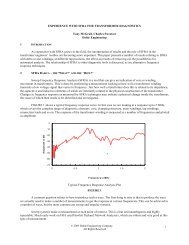
[2] “Experience with <strong>SFRA</strong> for <strong>Transformer</strong> Diagnostics” - Doble Engineering Company USA- Year 2003<br />
[3] “Experience with Sweep Frequency Response Analysis (<strong>SFRA</strong>) Measurements” - Doble Engineering<br />
Company USA- Year 2002<br />
BIOGRAPHY<br />
Arun D Yargole joined Doble Engineering in March 2010. Currently he is working as<br />
a Principal Client Engineer in INDIA. His prior experience includes 30 years with<br />
Global Research and Development Center of Crompton Greaves in Mumbai. During<br />
those years he worked in areas such as new product development in the field of power<br />
apparatus like dry transformers, RIP bushings, superconductor transformer,<br />
superconductor fault current limiter, etc. He developed high voltage test equipment<br />
such as inter-turn tester as per IEC 34-15 for high voltage machines, recurrent surge<br />
generators, impulse peak voltmeters, high voltage components and modules of solid<br />
state controller of impulse voltage generator.<br />
He is also an inventor of compact dry transformer that was granted a patent in US. He initiated a program on<br />
Condition Monitoring and Diagnostics, developed a team and worked for health check of about 100 power<br />
transformers. He published a paper titled “A Study of Sweep Frequency Analysis on Sister <strong>Transformer</strong>s” in<br />
CMD2006, in Korea.<br />
© 2011 Doble Engineering Company - 78 th Annual International Conference of Doble Clients<br />
All Rights Reserved<br />
8-8