Transformer Transportation Damage, A Case Presentation of a Low ...
Transformer Transportation Damage, A Case Presentation of a Low ...
Transformer Transportation Damage, A Case Presentation of a Low ...

Create successful ePaper yourself
Turn your PDF publications into a flip-book with our unique Google optimized e-Paper software.
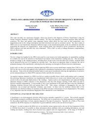
ABSTRACT<br />
TRANSFORMER TRANSPORTATION DAMAGE,<br />
A CASE PRESENTATION OF A LOW IMPACT EVENT<br />
Richard K. Ladroga<br />
Domenico E. Corsi<br />
William F. Griesacker<br />
Doble Global Power Services<br />
<strong>Transportation</strong> <strong>of</strong> large power transformers is typically costly and can sometimes become a substantial portion <strong>of</strong> the<br />
overall lead time <strong>of</strong> procuring a transformer. It is usually a positive milestone for both the manufacturer and the<br />
purchaser <strong>of</strong> a transformer when it reaches its final destination since both parties are one significant step closer to<br />
their respective objectives. When a transformer is damaged during shipment, both parties stand to loose. A recent<br />
low impact shipping event that resulted in the teardown and rebuilding <strong>of</strong> a large power generator step-up (GSU)<br />
transformer will be discussed to explain the shipping incident, damage to the transformer, the repairs and the lessons<br />
learned. Even though the impacts to the transformer were recorded at a low level, significant movement <strong>of</strong> the<br />
active parts gave reason for concern regarding the long term operation <strong>of</strong> the transformer.<br />
INTRODUCTION<br />
A new 450 MVA, large power GSU transformer was manufactured and shipped by rail to the purchasing utility’s<br />
site. During shipment the railcar that the transformer was transported on derailed at a relatively low speed, allowing<br />
the railcar to ride over the railroad ties. Despite the fact that the impact recorder registered relatively low impacts,<br />
the customer wisely took a cautious approach to ensure that their concerns <strong>of</strong> possible damage to the internal<br />
components <strong>of</strong> the transformer were fully investigated. They did not want to rely on electrical testing alone. Due to<br />
their insistence on conducting an internal inspection <strong>of</strong> the transformer, damage to the core and coil assembly was<br />
revealed that would eventually require returning the transformer to the factory for untanking, further inspection and<br />
repairs.<br />
BACKGROUND INFORMATION<br />
A utility began the process <strong>of</strong> evaluating one <strong>of</strong> their main GSU transformers. This transformer was in service at the<br />
power plant for almost 30 years. The operating and maintenance history <strong>of</strong> this transformer included several known<br />
conditions that could degrade over time and possibly lead to a failure event. This transformer was the sole GSU<br />
responsible for transmitting 100 % <strong>of</strong> the power from the station to the grid, making it a critical piece <strong>of</strong> equipment.<br />
Given the importance <strong>of</strong> the main GSU transformer and other transformers at the power plant <strong>of</strong> similar age, the<br />
utility sought an experienced third party to evaluate the condition <strong>of</strong> this and other key transformers at the power<br />
plant. The results <strong>of</strong> the in-depth condition assessment <strong>of</strong> the power plant transformers led the utility to decide to<br />
replace the main GSU.<br />
The utility went through a vendor selection process and awarded the main GSU transformer contract. During<br />
contract negotiations the responsibility <strong>of</strong> shipping the transformer was discussed; the vendor requested the utility to<br />
accept FOB Factory, which would have placed ownership <strong>of</strong> the transformer with the utility during shipment [1].<br />
The utility’s decision to decline this responsibility would later prove to be critical based on the significant financial<br />
impact they would have been burdened with [2].<br />
© 2010 Doble Engineering Company -77 th Annual International Doble Client Conference<br />
All Rights Reserved
DERAILMENT EVENT<br />
<strong>Transportation</strong> <strong>of</strong> the 450 MVA transformer from the factory to the utility’s site required rail shipment given that the<br />
shipping weight was on the order <strong>of</strong> 500,000 lbs. While the transformer was being transferred in a railroad<br />
switching yard, the railcar became derailed. The railcar was traveling at a relatively low speed at the time <strong>of</strong> the<br />
derailment; the derailment event did not turn over the transformer or railcar. The impact recorder on the derailed<br />
railcar recorded the relatively low impacts <strong>of</strong> X: 0.5g, Y: 3.0g and Z: 0.5g. One rail twisted over on its side due to<br />
the weight <strong>of</strong> the transformer and railcar. It was reported that the transformer and railcar traveled the length <strong>of</strong> about<br />
one railcar on the rail ties, see Figure 1. It was believed that riding over the rail ties subjected the transformer to a<br />
short but significant vibration event due to the multiple low level impacts that it experienced [3].<br />
Derailment <strong>of</strong> <strong>Transformer</strong> Railcar during Shipment<br />
Figure 1<br />
There were some external signs <strong>of</strong> possible damage to the transformer but they were not significant. The paint on<br />
some tank end gusset welds had small hairline cracks indicating that the weld joint was overstressed. The paint at<br />
the bottom base plate braces was chipped <strong>of</strong>f indicating contact between the tank base and bracing members.<br />
Neither <strong>of</strong> these was proven to be due to the derailment event and they did not appear to be significant or to indicate<br />
other possible damage. The electrical acceptance testing performed on the transformer upon arrival at the utility’s<br />
site did not indicate any problems with the transformer. SFRA testing was performed and there were no major<br />
problems detected but the results were inconclusive since there was no reference test performed before shipment that<br />
could be used for comparison purposes.<br />
The manufacturer, at this point in time, did not believe that there was damage sustained to the transformer and did<br />
not recommend any further investigation <strong>of</strong> the incident; however, the purchaser arranged for an internal inspection<br />
<strong>of</strong> the transformer before accepting the unit.<br />
INTERNAL INSPECTION<br />
An internal inspection <strong>of</strong> the transformer was performed at the utility’s site before the transformer was removed<br />
from the railcar. The unit was opened up and a dry air supply connected to the tank to help reduce the exposure <strong>of</strong><br />
the cellulose insulation to moisture. The core and coils assembly and mechanical members were inspected. As is<br />
common with many transformers designed in recent years, the internal clearances were tight and limited access at<br />
times during the inspection.<br />
The internal inspection identified signs <strong>of</strong> overall movement <strong>of</strong> the core and coil assembly with respect to the tank.<br />
Tear marks in the pressboard isolation sheets used between the bottom <strong>of</strong> the core clamps and the tank bottom<br />
indicated longitudinal movement <strong>of</strong> the core and coils assembly relative to the tank, see Figure 2. The pressboard<br />
sheets were held in place with a steel locating pin welded to the tank bottom and a “guide rail” was located at the<br />
edge <strong>of</strong> the sheets. The sheets showed tear marks from the locating pins and “guide rails”, evidence that the core<br />
and coils assembly moved about 2 in. from end-to-end with respect to the tank base plate during shipment.<br />
© 2010 Doble Engineering Company -77 th Annual International Doble Client Conference<br />
All Rights Reserved<br />
2
Tear Marks in Pressboard Isolation Sheets<br />
Between Bottom Core Clamp Feet and Tank Base Plate<br />
Figure 2<br />
There was evidence <strong>of</strong> movement <strong>of</strong> the core relative to the clamping frame blocks. Blocking material had shifted<br />
indicating longitudinal movement between the core and the core blocking and clamping frame, based on the<br />
displacement <strong>of</strong> the material, the displacement <strong>of</strong> the blocking material indicated movement up to ½ in.<br />
It was observed that each winding phase package had blocks between the coils and the top clamping ring that were<br />
loose, shifted and in some cases completely displaced from the radial column. Figure 3 shows a shifted block, some<br />
blocks were observed with as little as 50% <strong>of</strong> the surface area remaining in contact to transmit the clamping forces<br />
to the coils. The left frame in Figure 4 shows an example <strong>of</strong> a block over the outside winding that was completely<br />
knocked <strong>of</strong>f <strong>of</strong> the radial spacer column and the right frame shows a block over an inner winding that was also<br />
displaced <strong>of</strong>f its column. There were a considerable number <strong>of</strong> blocks that were either shifted or displaced from<br />
their column. A large number <strong>of</strong> the remaining blocks over the windings were loose. Due to the condition <strong>of</strong> the<br />
blocking, it was apparent that the windings were loose and susceptible to damage or even failure if they were subject<br />
to a short circuit event(s).<br />
Example <strong>of</strong> Shifted Top Coil Block<br />
Figure 3<br />
© 2010 Doble Engineering Company -77 th Annual International Doble Client Conference<br />
All Rights Reserved<br />
3
Examples <strong>of</strong> Coil Blocks (Between Coils and Top Clamping<br />
Ring) Displaced from their Radial Spacer Column<br />
Figure 4<br />
Wraps were used on the outside <strong>of</strong> the windings. On one winding a segment <strong>of</strong> the wrap had slipped down over the<br />
blocks and was resting on the bottom clamping ring, blocking oil flow to about 1/3 <strong>of</strong> the bottom ducts, see Figure 5.<br />
This was possible since the wrap was made <strong>of</strong> more than one piece <strong>of</strong> pressboard, one segment <strong>of</strong> the wrap had<br />
shifted down.<br />
Shifted<br />
Wrap<br />
Outside Winding Wrap Segment that Shifted Down, Blocking Bottom Oil Flow Ducts<br />
Figure 5<br />
The main blocking located between the core clamping frames and the clamping rings showed shifting and<br />
displacement, see Figures 6 and 7. Figure 6 shows blocks at the clamping frame end; the two blocks labeled “A”<br />
and “B” should be parallel. Block “A” is oriented correctly but block “B” had pivoted about 45 to the right as<br />
shown. The block on the far right has sections that have also shifted. In Figure 7 it can be seen that glued layers <strong>of</strong><br />
the blocking separated, which allowed sections <strong>of</strong> the block to shift significantly. About 50% <strong>of</strong> the bearing surface<br />
<strong>of</strong> this large block was left in contact.<br />
© 2010 Doble Engineering Company -77 th Annual International Doble Client Conference<br />
All Rights Reserved<br />
4
A<br />
B<br />
Shifted Top End Block Located between the<br />
Core Frame and Top Clamping Ring<br />
Figure 6<br />
Shifted Top Block Located between the<br />
Core Frame and the Top Clamping Ring<br />
Figure 7<br />
Cracks were identified in some lead support beams, see Figure 8. The lead support beams were made <strong>of</strong> laminated<br />
pressboard; the cracks were parallel to the lamination surfaces. It was not possible to determine if the cracks in the<br />
beams were a direct result <strong>of</strong> the derailment event but they were observed and noted.<br />
Lead Support Beams with Cracks along Lamination Surfaces<br />
Figure 8<br />
The internal inspection <strong>of</strong> the transformer revealed several conditions that would require repair work before the<br />
transformer could be commissioned for service. There were indications <strong>of</strong> movement <strong>of</strong> the internal assembly,<br />
which gave rise to concerns that there may be further damage to the core and coils that was not observed due to<br />
limited access and the limitations <strong>of</strong> inspecting an assembled transformer. There were a large number <strong>of</strong> main<br />
blocks between the clamping rings and the core frame that had shifted, some were loose. A large number <strong>of</strong> the top<br />
coil blocks located between the coils and the top clamping rings were loose. A large number <strong>of</strong> these coil blocks<br />
were shifted, leaving partial coverage <strong>of</strong> the block surface area to transmit the clamping forces to the coils. There<br />
were also a large number <strong>of</strong> coil blocks that had been knocked <strong>of</strong>f their respective radial spacer columns and were<br />
lying in the cooling ducts at the top <strong>of</strong> the coils. It was understood that the coil blocks in the core window area<br />
would probably not be able to be repaired in the field due to access limitations. The winding package had a large<br />
radial build since there were four windings in the radial direction, this would also limit access to make the repairs<br />
needed on the inner coils. The inner coils had the most top blocks completely displaced from their radial spacer<br />
© 2010 Doble Engineering Company -77 th Annual International Doble Client Conference<br />
All Rights Reserved
columns. The outside wraps over the windings, limited room in the tank and the normal obstructions <strong>of</strong> a fully<br />
assembled transformer prevented a comprehensive inspection <strong>of</strong> the active parts. However, the blocking items that<br />
were inspected showed movement and in some cases it was significant.<br />
The utility decided that they should receive a transformer in a “new” condition and based on these findings they<br />
requested that the transformer be returned to the factory to make further inspections and perform the repairs with<br />
proper access and tooling. The manufacturer decided that the repairs at the customer’s site were possible and<br />
proceeded to make preparations for field repairs.<br />
FIELD REPAIRS<br />
The transformer utilized a fixed clamping frame design. A hydraulic jack was placed between the top core clamping<br />
frame and the top clamping ring to press the winding package down and remove the top main blocks (the blocks<br />
between the top frame and top clamping ring). Due to limited access only one hydraulic jack was used, so jacking<br />
was performed at one location at a time. With the main blocks removed, the pressure was relieved from the coils in<br />
that area allowing blocks that were shifted to be tapped back into place. Shifted coil blocks at the top <strong>of</strong> the outer<br />
windings were realigned by tapping them back in place while the pressure was released. Blocks knocked <strong>of</strong>f the<br />
radial spacer columns on the outer coils were put back in place but this was not an easy task for the blocks over the<br />
inner coils because <strong>of</strong> the limited access. The space available to access the inner coil blocks in the top cooling duct<br />
was about 5 in. wide, 1.5 in. high and 15 in. deep. This proved to be very difficult to manipulate the displaced<br />
blocks back onto their radial spacer columns, in many cases the blocks could not be realigned back onto the radial<br />
spacer columns over the inner windings.<br />
As the work proceeded it became more apparent that the repairs would not be adequate to return the transformer to a<br />
new condition primarily due to the limited access in the tank. The blocks in the core window region on each phase<br />
winding package were not accessible. The blocks over the inside coils were all but inaccessible and it was not<br />
possible to place many <strong>of</strong> them back on their columns. Nearly 25 to 30 % <strong>of</strong> the inside winding blocks were <strong>of</strong>f<br />
their radial columns. After the tightening procedure was performed, the windings were inspected again. It was<br />
recognized after several attempts to tighten the windings that some areas still remained loose. Loose blocks were<br />
identified in the blocking over each coil <strong>of</strong> each winding phase assembly.<br />
At the conclusion <strong>of</strong> the field repair work, the manufacturer agreed to return the transformer to the factory for<br />
further inspection and repairs. The major inspection and repair work to be addressed at the factory included the<br />
following:<br />
<br />
<br />
<br />
<br />
<br />
<br />
Remove core and coils assembly from tank to allow adequate access to perform repairs.<br />
Thorough inspection <strong>of</strong> core and coils and tank.<br />
Remove top yoke and top clamping rings to allow inspection <strong>of</strong> the coils.<br />
Removal <strong>of</strong> outer pressboard wraps to facilitate inspection <strong>of</strong> the main outside HV winding.<br />
Realignment <strong>of</strong> blocking.<br />
Retightening <strong>of</strong> coils.<br />
UNTANKING AND INSPECTION<br />
Due to the tight clearances between the top <strong>of</strong> the core and the cover, it was difficult to inspect the top core yoke.<br />
Once the cover was removed, some problems were quickly identified. Overall, the top core yoke had mild but<br />
noticeable waves throughout the laminations that became increasingly worse as they progressed to one end, where<br />
they appeared to build up to a single large ripple that crossed nearly all steps <strong>of</strong> the yoke, see Figure 9. The miter<br />
joints at each end <strong>of</strong> the top yoke did not show signs <strong>of</strong> opening up, except in one location involving about three<br />
© 2010 Doble Engineering Company -77 th Annual International Doble Client Conference<br />
All Rights Reserved<br />
6
laminations. Although, it appeared that the top yoke steel had shifted toward one end and the large wave was a<br />
result <strong>of</strong> the lamination displacement being stopped by the miter joint and clamping frame at that end.<br />
Top Core Yoke Movement, LV Left and HV Right<br />
A Large Wave Present at One End <strong>of</strong> the Top Yoke<br />
Figure 9<br />
There were other indications <strong>of</strong> top core yoke movement. Outside laminations on one side <strong>of</strong> the yoke were buckled<br />
as shown in Figure 10. Apparently part <strong>of</strong> the laminations experienced movement in one area and did not move in<br />
another area, causing a buckling effect in several laminations to make up for the difference in relative movement.<br />
At one end <strong>of</strong> the rippled sheets, the miter joint was observed to have opened up, see the right frame in Figure 10. It<br />
was apparent that these gap openings were caused by the shipping derailment event. Generally all other miter joints<br />
on the core had small uniform gaps. The core laminations at the top miter joint were protected with thin insulating<br />
sheets as shown in the right frame <strong>of</strong> Figure 10.<br />
Core Movement<br />
Left Frame - Outside Laminations Buckled<br />
Right Frame - Miter Joint Opened due to Displacement <strong>of</strong> the Laminations<br />
Figure 10<br />
After the top yoke was removed, it was revealed that the buckled laminations, shown in the left frame <strong>of</strong> Figure 10,<br />
were deformed from top to bottom, i.e. across the entire width <strong>of</strong> the sheets, see Figure 11.<br />
© 2010 Doble Engineering Company -77 th Annual International Doble Client Conference<br />
All Rights Reserved<br />
7
Example <strong>of</strong> Buckled Core Lamination<br />
Figure 11<br />
It appeared that the top yoke laminations shifted toward the end where the derailment impact occurred. When the<br />
laminations were removed from the top core yoke, some displayed deformation along the miter cut edge at one end,<br />
see Figure 12. The deformation consisted <strong>of</strong> groups <strong>of</strong> parallel ridges that appeared to be due to compression <strong>of</strong> the<br />
yoke steel at the miter joint during the derailment event. It appeared that the ridges were created by the <strong>of</strong>fset edges<br />
<strong>of</strong> the step lapped joint. The insulation was breaking away from the core steel at some <strong>of</strong> the deformed ridges.<br />
Examples <strong>of</strong> Core Steel Deformation near the Miter Cut Edges<br />
Figure 12<br />
When the core yoke was removed additional damage to the core steel was revealed. In one location a core block<br />
came loose causing damage to the core steel on the edges, see Figure 13. The insulation had delaminated from the<br />
steel due to the mechanical deformation and the steel was cracked in some locations, as indicated in the right frame<br />
<strong>of</strong> Figure 13 with a red arrow. This damage was localized to the area shown in the figure.<br />
Top Core Yoke Steel <strong>Damage</strong> due to a Loose Block<br />
Figure 13<br />
© 2010 Doble Engineering Company -77 th Annual International Doble Client Conference<br />
All Rights Reserved<br />
8
Other than the damage discussed, the top miter joints <strong>of</strong> the core were tight with small and relatively uniform gaps.<br />
The miter joints at the bottom <strong>of</strong> the core did not display any detectable signs <strong>of</strong> movement.<br />
There were a number <strong>of</strong> insulating spacers that were loose and out <strong>of</strong> place. There was a cooling duct spacer<br />
dislodged and falling out <strong>of</strong> the bottom core yoke, it was identified when the core and coils assembly was being<br />
removed from the tank, see Figure 14. A second core duct spacer was also partially dislodged and observed to have<br />
fallen down. The manufacturer explained that these spacers are black due to the adhesive that is used to attach them<br />
to the core steel. A pressboard spacer under an end yoke block had broken free and had fallen down, see Figure 15.<br />
Displaced Core Duct Spacers<br />
Figure 14<br />
Displaced Core End Block Spacer<br />
Figure 15<br />
Once the top core yoke and top rings were removed, the top <strong>of</strong> the windings, insulation and blocking were inspected.<br />
Some axial spacers adjacent to windings and between cylinders were loose and had shifted. Figure 16 shows an<br />
example <strong>of</strong> loose and displaced axial spacers. It was observed that there was probably some shifting <strong>of</strong> the windings<br />
evident by the non-uniform gaps that were identified between windings and barrier cylinders see Figure 17. Due to<br />
the signs <strong>of</strong> movement at the top <strong>of</strong> the windings, the manufacturer decided that further investigation was warranted<br />
and the windings were removed from the core and the main coils were separated. Some <strong>of</strong> the gaps between coils,<br />
axial sticks and barrier cylinder were on the order <strong>of</strong> ½ in. on one side, while no measurable gap was present on the<br />
other side. The gaps were not uniform and were more than what would be expected for a typical manufacturing<br />
tolerance.<br />
Loose and Displaced Axial Sticks in Main High-<strong>Low</strong> Barrier<br />
Figure 16<br />
© 2010 Doble Engineering Company -77 th Annual International Doble Client Conference<br />
All Rights Reserved<br />
9
Gaps Observed at the Top <strong>of</strong> the Windings.<br />
Figure 17<br />
The core dimensions were measured after the windings were removed and it was reported that there was no<br />
detectable movement in the core limbs.<br />
REPAIRS<br />
The objective <strong>of</strong> the repairs from the perspective <strong>of</strong> the utility was to return the transformer to a new condition. The<br />
following list notes the major repairs made to the transformer:<br />
<br />
<br />
<br />
Replacement <strong>of</strong> top core yoke laminations that were damaged. There was damage due to shifting <strong>of</strong> the<br />
yoke steel that caused buckling and permanent deformation <strong>of</strong> some laminations. A loose or shifted block<br />
near the core came in contact with the steel and caused damage. Handling <strong>of</strong> the laminations also created<br />
some damage, especially at the miter joints.<br />
The main blocks between the clamping rings and the core clamping frames were twisted and several<br />
showed separation at the glue lines between the pieces making up the blocks. Typically, high density<br />
laminated wood material used in transformers has a shiny platen surface which prevents adhesives from<br />
bonding properly to the surface. To help with adhesion, the blocks were separated and scuffed to remove<br />
the shiny surfaces to allow proper bonding. Two (2) wooden dowel pins were added to each block through<br />
all layers to prevent the pieces <strong>of</strong> the blocks from shifting and pivoting. The blocks were aligned properly<br />
as they were reassembled between the frames and clamping rings.<br />
The top coil blocks were realigned and glued in place. The blocks at the top <strong>of</strong> individual coils were placed<br />
back on their radial spacer columns, aligned properly and glued in place.<br />
© 2010 Doble Engineering Company -77 th Annual International Doble Client Conference<br />
All Rights Reserved<br />
10
The main outer HV coil was separated from the other coils for inspection. When the coils were<br />
reassembled, the gaps between coils were filled with pressboard packing.<br />
<br />
<br />
Lead support members with damage were repaired or replaced.<br />
The bottom blocks supporting the outside winding wraps were moved to provide more margin so that the<br />
wraps would not slip over the blocks.<br />
The transformer received complete re-processing since the exposure period during the repair process was over an<br />
extended period <strong>of</strong> time. The original factory acceptance test plan was repeated due to the extensive teardown,<br />
repair and rebuilding <strong>of</strong> the transformer.<br />
CONCLUSION<br />
A recorded low impact event resulted in a major inspection and repair effort to bring a large power transformer back<br />
to a new condition. The important lessons learned from this experience include the following points:<br />
<br />
<br />
<br />
<br />
<br />
The magnitude <strong>of</strong> recorded events during transportation may not reveal the true nature <strong>of</strong> the internal<br />
condition <strong>of</strong> a transformer subsequent to an impact. Although the recorded impact magnitude was low, it is<br />
concluded from the damage found that the multiple low level impacts experienced from the rail car riding<br />
over the rail ties, imparted a quick succession <strong>of</strong> impacts to the transformer that was similar to a severe<br />
vibration event.<br />
Understand the implications <strong>of</strong> the contracts when they are negotiated and accepted. This is very basic<br />
advice but in this case the difference in one word, FOB Factory or FOB Destination, would have had a<br />
significant financial impact on the purchasing utility. The purchasing utility was requested during contract<br />
negotiations to accept FOB Factory, this would have put a large portion <strong>of</strong> the financial burden <strong>of</strong> repairing<br />
the transformer on the utility if they would have accepted this condition.<br />
The utility’s initiative to follow up on this seemingly small impact event has probably prevented a failure<br />
and subsequent unscheduled outage, considering the true condition <strong>of</strong> the transformer that was uncovered<br />
during internal inspections. The conservative approach and thoroughness in investigating the transformer<br />
condition while under pressure to meet project deadlines proved to be invaluable.<br />
In this case, if SFRA testing would have been conducted at the factory, the results may have been helpful in<br />
diagnosing the damage and expediting the inspection and repair process.<br />
A conventional strip chart recorder was used to monitor the shipment <strong>of</strong> this transformer. There are impact<br />
recorders available that <strong>of</strong>fer more capabilities [4], some recorders have features that include tracking the<br />
time, geographic location and impact events by digital means. Some impact recorders can transmit this<br />
data as it is collected allowing continuous monitoring <strong>of</strong> shipping progress and recorded impact events.<br />
REFERENCES<br />
[1] Horning, M., “Site Installation”, The Life <strong>of</strong> a <strong>Transformer</strong> Seminar, 2007, Doble Engineering Company.<br />
[2] Betancourt, E., Hernandez, C. H., “Large Power <strong>Transformer</strong> <strong>Transportation</strong>, A Manufacturer’s Perspective”,<br />
The Life <strong>of</strong> a <strong>Transformer</strong> Seminar, 2009, Doble Engineering Company.<br />
[3] Hansen, N. W., “Power <strong>Transformer</strong> Rail Shipment: A Manufacturer’s Viewpoint”, Proceedings <strong>of</strong> the 1993<br />
International Conference <strong>of</strong> Doble Clients, 1993, Sec 6-7.<br />
[4] Baker, D., “Impact Recorders”, The Life <strong>of</strong> a <strong>Transformer</strong> Seminar, 2007, Doble Engineering Company.<br />
© 2010 Doble Engineering Company -77 th Annual International Doble Client Conference<br />
All Rights Reserved<br />
11
BIOGRAPHY<br />
Bill Griesacker is a member <strong>of</strong> Doble Global Power Services, he is employed as a transformer engineer, working on<br />
projects that include forensic analysis, factory inspections, condition assessment, design reviews and general<br />
consulting. He previously worked for Pennsylvania <strong>Transformer</strong> Technology Inc., where he held various positions<br />
including Engineering Manager. His worked included high voltage insulation design, transient voltage modeling <strong>of</strong><br />
power transformer windings and development <strong>of</strong> LTC and DETC switches. He also worked for Westinghouse in the<br />
Generator Engineering Department on synchronous generator projects. Bill started his career with Cooper Power<br />
Systems in large power transformers and later worked in the Kyle Switchgear, Vacuum Interrupter Department. He<br />
has earned a M.S. degree in electric power engineering from the Rensselaer Polytechnic Institute and a B.S. degree<br />
in electrical engineering from Gannon University. Bill is an active member <strong>of</strong> the IEEE, PES <strong>Transformer</strong>s<br />
Committee where he holds positions in several working groups and subcommittees.<br />
© 2010 Doble Engineering Company -77 th Annual International Doble Client Conference<br />
All Rights Reserved