Transformer Transportation Damage, A Case Presentation of a Low ...
Transformer Transportation Damage, A Case Presentation of a Low ...
Transformer Transportation Damage, A Case Presentation of a Low ...

You also want an ePaper? Increase the reach of your titles
YUMPU automatically turns print PDFs into web optimized ePapers that Google loves.
Example <strong>of</strong> Buckled Core Lamination<br />
Figure 11<br />
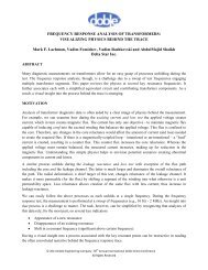
It appeared that the top yoke laminations shifted toward the end where the derailment impact occurred. When the<br />
laminations were removed from the top core yoke, some displayed deformation along the miter cut edge at one end,<br />
see Figure 12. The deformation consisted <strong>of</strong> groups <strong>of</strong> parallel ridges that appeared to be due to compression <strong>of</strong> the<br />
yoke steel at the miter joint during the derailment event. It appeared that the ridges were created by the <strong>of</strong>fset edges<br />
<strong>of</strong> the step lapped joint. The insulation was breaking away from the core steel at some <strong>of</strong> the deformed ridges.<br />
Examples <strong>of</strong> Core Steel Deformation near the Miter Cut Edges<br />
Figure 12<br />
When the core yoke was removed additional damage to the core steel was revealed. In one location a core block<br />
came loose causing damage to the core steel on the edges, see Figure 13. The insulation had delaminated from the<br />
steel due to the mechanical deformation and the steel was cracked in some locations, as indicated in the right frame<br />
<strong>of</strong> Figure 13 with a red arrow. This damage was localized to the area shown in the figure.<br />
Top Core Yoke Steel <strong>Damage</strong> due to a Loose Block<br />
Figure 13<br />
© 2010 Doble Engineering Company -77 th Annual International Doble Client Conference<br />
All Rights Reserved<br />
8