Electric SPA-PAK Heater - Rheem
Electric SPA-PAK Heater - Rheem
Electric SPA-PAK Heater - Rheem
You also want an ePaper? Increase the reach of your titles
YUMPU automatically turns print PDFs into web optimized ePapers that Google loves.
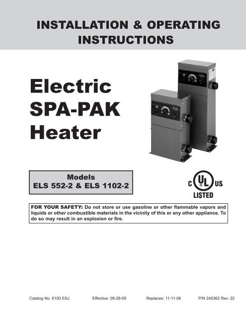
INSTALLATION & OPERATING<br />
INSTRUCTIONS<br />
<strong>Electric</strong><br />
<strong>SPA</strong>-<strong>PAK</strong><br />
<strong>Heater</strong><br />
Models<br />
ELS 552-2 & ELS 1102-2<br />
FOR YOUR SAFETY: Do not store or use gasoline or other flammable vapors and<br />
liquids or other combustible materials in the vicinity of this or any other appliance. To<br />
do so may result in an explosion or fire.<br />
Catalog No. 6100.53U Effective: 09-28-09 Replaces: 11-11-08 P/N 240362 Rev. 22
WATER CHEMISTRY<br />
For your health and the protection of your pool equipment,<br />
it is essential that your water be chemically<br />
balanced. The following levels must be used as a<br />
guide for balanced water.<br />
CAUTION: Corrosive water voids all warranties.<br />
Occasional chemical shock dosing of the pool or spa<br />
should not damage the heater providing the water is<br />
balanced.<br />
Automatic chemical dosing devices and salt chlorinators<br />
are usually more efficient in heater water, unless<br />
controlled, they can lead to excessive chlorine level<br />
which can damage your heater.<br />
Further advice should be obtained from your pool or<br />
spa builder, accredited pool shop, or chemical supplier<br />
for the correct levels for your water.<br />
Recommended<br />
Level(s)<br />
Fiberglass Pools<br />
Fiberglass Spas<br />
Other Pool and Spa<br />
Types<br />
Water Temperature 68-88°F (20-31°C) 89-104°F (31-40°C) 68-104°F (20-40°C)<br />
pH 7.3-7.4 7.3-7.4 7.6-7.8<br />
Total Alkalinity (ppm) 120-150 120-150 80-120<br />
Calcium Hardness (ppm) 200-300 150-200 200-400<br />
Salt (ppm) 6000 Maximum 6000 Maximum 6000 Maximum<br />
Free Chlorine (ppm)* 2-3 2-3 2-3<br />
Total Dissolved Solids<br />
(ppm)<br />
3000 Maximum 3000 Maximum 3000 Maximum<br />
*Free Chlorine MUST NOT EXCEED 5 ppm!<br />
Rev. 22 reflects the following: Changes to: The C-UL Listed Mark on page 1.<br />
2
INTRODUCTION<br />
NOTE: PVC pipe may be used.<br />
The Spa-Pak spa <strong>Heater</strong>s have been designed to provide<br />
efficient, pollution-free, electric pool heating while<br />
requiring minimal installation. The Spa-Pak consists of<br />
a sheathed resistance element installed in a copper<br />
tank.<br />
NOTE: When using two speed pumps, do not install<br />
gate valve on inlet.<br />
This tank has a 1-1/2” inlet and outlet on the side for<br />
plumbing connections. The heater voltage is 208/240V<br />
single-phase. The control circuit passes through a<br />
manual switch, the temperature control, and the magnetic<br />
contactor coil. All items are pre-wired and<br />
installed in a baked enamel steel case.<br />
It is essential that the heater be installed in accordance<br />
with the instructions given herein. Failure to do<br />
so may cause damage to the heater and to the equipment<br />
to which it is connected, or may prevent the<br />
heater from operating in a correct manner. The heater<br />
is to be installed in accordance with article 680 of the<br />
National <strong>Electric</strong>al Code ANSI/NFPA No. 70. Consult<br />
State and local codes BEFORE installing this unit.<br />
Where such codes have requirements beyond the<br />
instructions given herein, the codes shall have precedence<br />
over these instructions.<br />
Location<br />
These heaters are listed by UL for either indoor or outdoor<br />
use. Unit must be mounted on a level base<br />
parallel to the ground. Allow 6” clearance at sides and<br />
18” clearance at top and front for maintenance. Secure<br />
the unit with 5/16” mounting hardware using the holes<br />
provided. The heater must be located where leakage<br />
of heat exchanger or connections will not damage the<br />
area adjacent to the heater or structure.<br />
Water Connections<br />
Check Valve<br />
To Spa<br />
Filter<br />
Chlorinator<br />
The Spa-Pak has 1-1/2” male NPT inlet and outlet<br />
connections at the right side of the heater. The inlet is<br />
at the base of the heater and must be piped directly to<br />
the filter discharge to ensure proper flow direction.<br />
Minimum flow rate through the heater is 15 gpm, maximum<br />
is 60 gpm. If this is exceeded, an external<br />
bypass must be added as shown. Unions should be<br />
used on piping connections. A shut-off valve should be<br />
included on the heater inlet to prevent draining the spa<br />
when performing maintenance.<br />
CAUTION: No shut-off valves are to be installed in<br />
the piping between the heater outlet and the spa.<br />
Any chlorinators, valves, etc., that can cause return<br />
line blockage will void the warranty.<br />
Automatic Chlorinators and<br />
Chemical Feeders<br />
All chemicals must be introduced and completely diluted<br />
into the spa water before being circulated through<br />
the heater. Do not place chlorine tablets or bromine<br />
sticks in the skimmer. High chemical concentrations<br />
will result when the pump is not running (e.g.<br />
overnight).<br />
Bypass<br />
(Customer Installed)<br />
Drain Valve<br />
(Customer Installed)<br />
Gate Valve<br />
From Spa<br />
Pump<br />
Chlorinators must feed downstream of the heater and<br />
have an anti-siphoning device to prevent chemical<br />
backup into the heater when the pump is shut off.<br />
3
CAUTION: High chemical concentrates from feeders<br />
and chlorinators that are out of adjustment will<br />
cause very rapid corrosion to the heater. Such damage<br />
is not covered under the warranty.<br />
Thermostat<br />
The heater thermostat located on the front of the unit,<br />
may be set for any desired spa temperature.<br />
codes. Keep wire runs as short as possible to minimize<br />
voltage drop. Bring wires of size indicated from a<br />
fused disconnect switch (customer furnished) with an<br />
amp rating of at least 125% of the amp rating shown<br />
on the spa heater nameplate. A ground lug is provided<br />
for connection to the supply ground. A wiring diagram<br />
of the heater is shown at right. It is also affixed to the<br />
inside front cover of the units.<br />
Field Wiring<br />
TYPICAL COMFORTABLE<br />
TEMPERATURE<br />
RANGE FOR <strong>SPA</strong>S<br />
TYPICAL COMFORTABLE<br />
TEMPERATURE<br />
RANGE FOR POOLS<br />
<strong>Heater</strong> requires three-wire service. With 240 VAC<br />
there are two hot wires and a grounding conductor.<br />
Even when metallic conduit is used, the grounding<br />
conductor must be run to the supply ground.<br />
Field wiring connections are made to the electrical<br />
entry at the left side of the unit. A hole in the jacket is<br />
provided for a 1” trade size conduit hub. The location<br />
of the field wiring box is shown below. Wire nuts are<br />
used to connect all leads except the grounding conductor,<br />
for which a pressure lug is provided.<br />
NOTE: <strong>Heater</strong> grounding conductor shall be the<br />
same or larger than the live power supply conductor.<br />
Maximum Temperature Setpoint<br />
(Knobstop Adjustment)<br />
Adjustment to a different maximum setting is a simple<br />
task. Loosen the small set screw on the knobstop and<br />
rotate the knobstop ring until vertical “stop” tab is at the<br />
desired maximum setting. Retighten the set screw.<br />
ELECTRICAL<br />
WARNING: The power supply circuit to this heater<br />
shall be protected by a ground-fault circuit interrupter<br />
(GFCI), in accordance with Art. 680 of the latest edition<br />
of the National <strong>Electric</strong>al Code (NEC). Failure to<br />
do so could result in severe personal injury or death.<br />
The GFCI devices shall be of the self-contained types,<br />
circuit breaker types or the receptacle types. Feeder<br />
ground-fault protection is not required where GFCI is<br />
already provided in the branch circuits or receptacles<br />
supplying power to the heater.<br />
<strong>Electric</strong>al Disconnect<br />
An electrical disconnect and over-current protection<br />
device must be provided in accordance with local<br />
Recommended Wire Sizes<br />
for Field Connection<br />
Use type THWN copper wire to the unit, with the AWG<br />
wire sizes (Internal wire sizes may differ) listed in Table<br />
A on the following page.<br />
4
Model Amp Draw Conduit Size<br />
Wire Size<br />
(including<br />
ground)<br />
Size of Fused<br />
Disconnect (amps)<br />
ELS 1102-2 46 1” 6 60<br />
ELS 552-2 23 *1/2” 10 30<br />
*Use a reducer bushing.<br />
Table A: Wire Sizes for Field Connection<br />
LADDER DIAGRAM<br />
L1<br />
L2<br />
SCHEMATIC DIAGRAM<br />
MODEL<br />
ELS 552-2<br />
ONLY<br />
5
Controls<br />
Spa-Pak spa heaters have integral thermostats and<br />
contactors. They are also equipped with a high temperature<br />
limit thermostat which will open the circuit<br />
cutting off power to the heating element in the event of<br />
excessive water temperature. This high limit thermostat<br />
is factory set at 140°F. A pressure switch is utilized<br />
to ensure water flow through the heater before the unit<br />
will function.<br />
NOTE: The filter must be kept clean so the flow rate<br />
will be maintained above 15 gpm. Failure to do so<br />
will cause the pressure switch to drop out, and the<br />
heater will become inoperative.<br />
OPERATION<br />
Preliminary<br />
MAKE SURE THAT POWER TO THE UNIT IS OFF.<br />
Remove any tools or other foreign objects from the<br />
inside of the unit. Replace the removable lower panel.<br />
Place temperature control in the off position. Check<br />
tightness of electrical screw terminals.<br />
Filling<br />
Open all valves in the inlet piping and fill the system<br />
with water. Turn on the filter pump and purge all air<br />
from the system. On in-ground spa installations it may<br />
be necessary to prime the pump. Check the unit and<br />
all piping connections for leaks.<br />
Start-up<br />
FILTER PUMP MUST BE ON FOR THE HEATER TO<br />
OPERATE. Turn on the main power to the unit, then<br />
set the temperature control to the desired position and<br />
turn the switch to the “ON” position to place the heater<br />
in operation. Shut pump off and on to be certain that<br />
heater shuts off when pump is off.<br />
A thermal cutout prevents the unit from overheating.<br />
Should overheating occur, the control circuit may be<br />
made operational by depressing the manual reset button<br />
through the grommet on the front panel. This will<br />
be possible only after the unit has cooled down for<br />
several minutes.<br />
IMPORTANT SAFETY<br />
INSTRUCTIONS<br />
CAUTION: Elevated water temperature can be<br />
hazardous.<br />
The U.S. Consumer Product Safety Commission recommends<br />
the following guidelines. When using this<br />
electrical equipment, basic safety precautions should<br />
always be followed, including the following:<br />
1. READ AND FOLLOW ALL INSTRUCTIONS.<br />
2. To reduce the risk of injury:<br />
a. The water in a pool or tub should never<br />
exceed 104°F (40°C). A water temperature in<br />
excess of 104°F is considered unsafe for all<br />
persons. Lower water temperatures are recommended<br />
for extended use (exceeding 10 –<br />
15 minutes) and for young children.<br />
b. Since excessive water temperatures have a<br />
high potential for causing fetal damage during<br />
the early months of pregnancy, pregnant or<br />
possibly pregnant women should limit pool or<br />
tub water temperatures to 100°F (38°C).<br />
c. Before entering a pool or tub, the user should<br />
measure the water temperature at several<br />
occupant locations using an accurate thermometer<br />
since the tolerance of water<br />
temperature-regulating devices may vary as<br />
much as ±5°F (±3°C).<br />
d. Alcohol, drugs, or medication should not be<br />
used before or during pool or tub use since<br />
their use may lead to unconsciousness with<br />
the possibility of drowning.<br />
e. Persons suffering from obesity or with a medical<br />
history of heart disease, low or high blood<br />
pressure, circulatory system problems, or diabetes<br />
should consult a physician before using<br />
a pool or tub.<br />
f. Persons using medication should consult a<br />
physician before using a pool or tub since<br />
some medication may induce drowsiness<br />
while other medication may affect heart rate,<br />
blood pressure, and circulation.<br />
6
WARNING: The use of alcohol, drugs, or medication<br />
can greatly increase the risk of fatal<br />
hyperthermia in pools and tubs.<br />
NOTE: Hyperthermia occurs when the internal temperature<br />
of the body reaches a level several degrees<br />
above the normal body temperature of 98.6°F<br />
(37°C). The symptoms of hyperthermia include dizziness,<br />
fainting, drowsiness, lethargy, and an increase<br />
in the internal temperature of the body. The effects of<br />
hyperthermia include (1) unawareness of impending<br />
hazard, (2) failure to perceive heat, (3) failure to recognize<br />
the need to exit pool or tub, (4) physical<br />
inability to exit pool or tub, (5) fetal damage in pregnant<br />
women, and (6) unconsciousness resulting in a<br />
danger of drowning.<br />
3. A green terminal (or wire connector marked "G",<br />
"GR", "GROUND" or "GROUNDING") is provided<br />
within the control box. To reduce the risk of electric<br />
shock, connect this terminal or connector to the<br />
grounding terminal of the electric service or supply<br />
panel with a continuous copper wire in accordance<br />
with the Canadian <strong>Electric</strong>al Code, Part I.<br />
4. This product shall be protected by a Class A<br />
ground fault circuit interrupter (GFCI).<br />
5. SAVE THESE INSTRUCTIONS.<br />
Pressure Switch Adjustment<br />
Pressure switch is normally factory set for universal<br />
spa applications. <strong>Heater</strong> must not be installed more<br />
than five feet above water level or five feet below. If the<br />
heater is installed below the spa level or if a two speed<br />
filter pump is used it is necessary to reset the pressure<br />
switch as follows:<br />
1. With pump and heater on, turn adjustment knob<br />
clockwise until a click is heard.<br />
2. Turn adjustment knob counter clockwise 1/4 turn.<br />
3. Turn pump off and on several times. <strong>Heater</strong> should<br />
shut off immediately. If it does not, repeat steps<br />
above until proper adjustment is made.<br />
Shut Down<br />
Turn off electrical power to heater at main disconnect<br />
when draining spa.<br />
MAINTENANCE<br />
WARNING: ONLY QUALIFIED PERSONNEL<br />
SHOULD ATTEMPT MAINTENANCE ON THIS<br />
EQUIPMENT (N.E.C. ARTICLE 100-1971) (MAIN-<br />
TENANCE MUST BE DONE WITH MAIN<br />
DISCONNECT OPEN).<br />
Spa Water Chemistry<br />
Chemical imbalance can cause severe damage to<br />
your heater and associated equipment. Maintain your<br />
water chemistry according to the chart on page 8. If<br />
the mineral content and dissolved solids in the water<br />
become too high, scale forms inside the heat exchanger<br />
tubes, reducing heater efficiency and also<br />
damaging the heater. If the pH drops below 7.2, the<br />
heater will be severely damaged. This will result in corrosion<br />
of the heat exchanger. Heat exchanger<br />
damage resulting from chemical imbalance is not<br />
covered by the warranty.<br />
Element Inspection and<br />
Replacement<br />
The element assembly head is removed as follows:<br />
1. Turn off electrical power to heater at the main disconnect<br />
and turn off water supply line.<br />
2. Drain the heater.<br />
3. Remove access panel.<br />
4. Disconnect all wires to terminals of elements.<br />
5. Remove four bolts holding element in place.<br />
6. Remove element assembly.<br />
7. Replace element assembly and gasket using<br />
reverse procedure.<br />
Removing the Aquastat<br />
1. Turn off electrical power to heater at main disconnect.<br />
2. Remove screw holding aquastat to mounting<br />
plate.<br />
3. Disconnect wires from aquastat and control knob.<br />
7
4. Remove retainer clip at bulb and remove capillary<br />
bulb.<br />
5. Remove aquastat, using extreme care to see that<br />
the capillary tube is not kinked or broken. (Never<br />
use anything but fingers to bend capillary tubing).<br />
Removing the High Limit<br />
1. Turn off electrical power to heater at main disconnect.<br />
2. Disconnect wires from high limit.<br />
3. Remove screws holding high limit to tank.<br />
Removing the Pressure Switch<br />
1. Turn off electrical power to heater at main disconnect.<br />
2. Drain heater.<br />
3. Disconnect pressure switch leads.<br />
4. Unscrew pressure switch.<br />
Removing the Magnetic<br />
Contactor<br />
1. Turn off electric power to heater at main disconnect.<br />
2. Remove wires from contactor.<br />
3. Remove screw holding contactor to cabinet.<br />
Winterizing<br />
Damage will occur if water is allowed to freeze inside<br />
the heater. Normally the heater will drain when the spa<br />
is drained. If the heater is positioned lower than the<br />
spa a drain valve must be added at the heater inlet.<br />
The water must be drained from the heater and the<br />
main disconnect switch shut off.<br />
Filter<br />
CAUTION: Do not allow filter to become clogged to<br />
the extent that cycling of the pressure switch occurs.<br />
This can result in accelerated wear of the magnetic<br />
contactor. Contactor damage caused by dirty filter is<br />
not covered by warranty.<br />
8
TROUBLESHOOTING<br />
Problem Cause Solution<br />
Nothing happens when the thermostat<br />
is turned on<br />
It takes a long time to heat the spa<br />
Spa does not reach temperature<br />
Heating element continuously<br />
burning out<br />
Continuous shutdown of manual<br />
reset high limit<br />
Fuses blow or circuit breaker<br />
opens<br />
Low flow..........................................<br />
High limit.........................................<br />
Thermostat not calling for heat.......<br />
Low input voltage…………………..<br />
Undersized heater……...................<br />
Heat loss from poor weather conditions<br />
(cold, high winds)……….....<br />
Defective heating element………...<br />
Mis-adjusted knob-stop……………<br />
Low flow……………………………..<br />
High input voltage………………….<br />
Poor water chemistry......................<br />
Heating element split open………..<br />
Mis-adjusted or defective pressure<br />
switch…………………….................<br />
Shorted heating elements………....<br />
Undersized wire…………………….<br />
1. Check filter, skimmer basket,<br />
pump.<br />
2. If a 2-speed pump is used, turn<br />
to high speed. If heater operates,<br />
adjust pressure switch for<br />
low speed operation.<br />
Push reset button.<br />
Turn thermostat to higher temperature.<br />
Call electric company.<br />
Calculate temperature in Heat rise<br />
°/hr.= <strong>Heater</strong> input (kw) x 410 divided<br />
by spa gallonage (This does not<br />
take into account heat loss due to<br />
weather).<br />
Use spa cover.<br />
Call electrician. Check resistance/<br />
element bundle:<br />
240V 11 kw = 5.0 to 5.8 OHMS<br />
240V 5.5 kw = 10.0 to 11.6 OHMS<br />
Re-adjust knob-stop.<br />
Check filter, skimmer basket,<br />
pump.<br />
Call electric company.<br />
See Water Chemistry on page 11.<br />
Over-acid condition. Watch pH,<br />
add acid slowly.<br />
Replace pressure switch.<br />
Replace element.<br />
Replace wire.<br />
Contactor hum<br />
Circuit breaker or fuses too small..<br />
Contactor contacts dirty or worn….<br />
(NOTE: Some hum is normal)<br />
Replace.<br />
Replace contactor.<br />
Contactor chatter Low flow…………………………….. Check filter skimmer basket and<br />
pump.<br />
9
12 9<br />
8<br />
PART DESCRIPTION ELS 552-2 ELS 1102-2<br />
1 Element<br />
001801F 001802F<br />
2 Element Gasket (Not Shown) 800164 800164<br />
3 Element Tube Assy. 001805F 001808F<br />
4 Sensor Well<br />
004087F 004087F<br />
5 Well Retaining Clip 300203 300203<br />
6 Pressure Switch 062237B 062237B<br />
7 High Limit<br />
001811F 001811F<br />
8 Contactor/Wire Kit 001813F 001813F<br />
9 Thermostat Control 003346F 003346F<br />
10 Toggle Switch<br />
650761 650761<br />
11 Indicator Light<br />
001812F 001812F<br />
12 Knob<br />
006885F 006885F<br />
13 Knobstop<br />
006886F 006886F<br />
14 Dial Plate<br />
900615 900615<br />
15 Wire Kit (Complete) N/A N/A<br />
16 Jacket Top<br />
N/A N/A<br />
17 Upper Front Panel<br />
N/A N/A<br />
18 Lower Front Panel<br />
N/A N/A<br />
10
www.raypak.com<br />
Raypak, Inc., 2151 Eastman Avenue, Oxnard, CA 93030 (805) 278-5300 Fax (805) 278-5468<br />
Litho in U.S.A.


