Jandy JE Pro Series Operation Manual - Poolheatpumps.com
Jandy JE Pro Series Operation Manual - Poolheatpumps.com
Jandy JE Pro Series Operation Manual - Poolheatpumps.com

You also want an ePaper? Increase the reach of your titles
YUMPU automatically turns print PDFs into web optimized ePapers that Google loves.
<strong>Jandy</strong> ® <strong>Pro</strong> <strong>Series</strong> <strong>JE</strong> Heat Pumps | Installation and <strong>Operation</strong> <strong>Manual</strong>Table of ContentsENGLISHPage 1Section 1. General Information...................31.1 Introduction.......................................................... 31.2 Consumer Information and Safety....................... 31.3 Warranty.............................................................. 41.4 Codes and Standards.......................................... 41.5 Technical Assistance........................................... 41.6 Materials Needed For Installation........................ 41.7 Specifications...................................................... 5Section 2. Installation Instructions.............52.1 General Information............................................. 52.2 Location Requirements....................................... 5Section 3. Water Connections ....................83.1 Plumbing Layout ................................................. 83.2 Water Connections at Heat Pump....................... 83.3 Check Valve Installation...................................... 83.4 Multiple Unit Installation...................................... 9Section 4. Electrical Connections..............94.1 General Information............................................. 94.2 Main Power....................................................... 104.3 Bonding............................................................. 154.4 Optional Remote Controls................................. 15Section 5. <strong>Operation</strong>..................................185.1 Initial Start-up Precautions................................ 185.2 Operating the Controller.................................... 185.3 Operating Features of Hybrid Units withOptional Chiller.................................................. 195.4 User Setup Options........................................... 205.5 Set Point Lockout.............................................. 215.6 Water Pressure Switch Adjustment................... 21Section 6. General Maintenance...............216.1 Water Chemistry................................................ 216.2 Winterizing......................................................... 226.3 Spring Start-Up.................................................. 226.4 Inspection and Service...................................... 22Section 7. <strong>Pro</strong>fessional Maintenanceand Service...............................237.1 Heat Pump Design............................................ 237.2 Heat Pump Components and <strong>Operation</strong>........... 23Section 8. Troubleshooting.......................258.1 Troubleshooting Guide...................................... 258.2 Diagnostics........................................................ 25Section 9. Replacement Parts...................269.1 Ordering Information......................................... 269.2 Zodiac <strong>JE</strong> Heat Pumps Parts List...................... 269.3 Zodiac <strong>JE</strong>1500 Heat Pumps Exploded View .... 279.4 Zodiac <strong>JE</strong>2000 Heat Pumps Exploded View .... 289.5 Zodiac <strong>JE</strong> Single Phase Electric Box................ 299.6 Zodiac <strong>JE</strong> Three Phase Electric Box................. 29Figures and TablesFigure 1. Zodiac ® <strong>JE</strong> Heat Pumps Dimensions..........7Figure 2. Anchor Clamp Positions.............................9Figure 3. Anchor Clamp Installation...........................9Figure 4. Standard Plumbing Layout....................... 11Figure 5. Plumbing For Heating SystemCombinations............................................ 11Figure 6. Two (2) Heat Pump Plumbing Layout.......12Figure 7. Four (4) Heat Pump Plumbing Layout......12Figure 8. <strong>JE</strong> Single-Phase Electrical SupplyWiring Diagram.........................................13Figure 9. <strong>JE</strong> 3-Phase Electrical Supply WiringDiagram....................................................14Figure 10. <strong>JE</strong> Heat Pump Front View........................15Figure 11a. Remote Pool-Off-Spa Connection(3-Wire Connection).................................16Figure 11b. AquaLink RS or Remote TSTATConnection (2-Wire Connection)..............16Figure 12. AquaLink ® RS to <strong>JE</strong> Heat Pump...............17Figure 13. <strong>JE</strong> Heat Pump Connection to PowerCenter.......................................................18Figure 14. Main Control Panel...................................20Figure 15. Winterizing the <strong>JE</strong> Heat Pump..................22Figure 16. Zodiac <strong>JE</strong>1500 Heat Pumps ExplodedView (<strong>JE</strong>1500 Shown)..............................27Figure 17. Zodiac <strong>JE</strong>2000 Heat Pumps ExplodedView (<strong>JE</strong>2000 Shown)..............................28Figure 18. Zodiac <strong>JE</strong> Heat Pump Single PhaseElectric Box...............................................29Figure 19. Zodiac <strong>JE</strong> Heat Pump Three PhaseElectric Box...............................................29Table 1. <strong>JE</strong> Heat Pump TechnicalSpecifications.............................................6Table 2. Heat Pump Clearances..............................7Table 3. Optimal Water Chemistry Ranges............23Table 4. Heat Pump Troubleshouting Guide..........24Table 5. Heat Pump Diagnostics............................25
Page 2ENGLISH<strong>Jandy</strong> ® <strong>Pro</strong> <strong>Series</strong> <strong>JE</strong> Heat Pumps | Installation and <strong>Operation</strong> <strong>Manual</strong>
<strong>Jandy</strong> ® <strong>Pro</strong> <strong>Series</strong> <strong>JE</strong> Heat Pumps | Installation and <strong>Operation</strong> <strong>Manual</strong>Section 1. General InformationENGLISHSpa/Hot Tub Safety RulesPage 31.1 IntroductionThis manual provides installation and operationinstructions for the <strong>Jandy</strong> <strong>Pro</strong> <strong>Series</strong> <strong>JE</strong> models ofheat pumps. Read these installation and operationinstructions <strong>com</strong>pletely before proceeding withthe installation. Consult Zodiac Pool Systems, Inc.(“Zodiac”) with any questions regarding this equipment.To obtain additional copies of this manual contact us at800-822-7933.Zodiac Pool Systems, Inc.2620 Commerce WayVista, CA 92081 USAThe <strong>Jandy</strong> <strong>Pro</strong> <strong>Series</strong> <strong>JE</strong> heat pump gets electrical powerfrom an external source and provides a dual digitalthermostat control system for pool/spa <strong>com</strong>binations orpreheat convenience.This heat pump is specifically designed for heatingfresh water swimming pools and spas. Do not use itas a general service heater. Consult your dealer for theappropriate Zodiac ® products for these applications.Note “Fresh water swimming pools and spas” includesystems that utilize saltwater chlorine generatorunits, such as the Zodiac AquaPure ® ElectronicChlorine Generator. Please ensure that the saltcontent of the pool/spa does not exceed4500 ppm and water flow rate is within30-70 gpm (110-265 lpm).AttentionInstallation and service must be performed bya qualified installer or service agency.To the Installer:To the User:After installation, theseinstructions must be given tothe homeowner or left on ornear the heat pump.This manual containsimportant information thatwill help you in operating andmaintaining this heat pump.Please retain it for futurereference.1.2 Consumer Information and SafetyThe <strong>Jandy</strong> <strong>Pro</strong> <strong>Series</strong> <strong>JE</strong> series of heat pumps aredesigned and manufactured to provide many years ofsafe and reliable service when installed, operated andmaintained according to the information in this manualand the installation codes referred to in later sections.Throughout the manual, safety warnings and cautionsare identified by the “ “ symbol. Be sure to read and<strong>com</strong>ply with all of the warnings and cautions.WARNINGThe U.S. Consumer <strong>Pro</strong>duct Safety Commissionwarns that elevated water temperature canbe hazardous. Consult heater operation andinstallation instructions for water temperatureguidelines before setting temperature.WARNINGThe following “Safety Rules for Hot Tubs,”re<strong>com</strong>mended by the U.S. Consumer <strong>Pro</strong>ductSafety Commission, should be observed whenusing the spa.WARNINGSpa or hot tub water temperature should neverexceed 104°F (40°C). One hundred degreesFahrenheit (100°F [38°C]) is considered safe fora healthy adult. Special caution is re<strong>com</strong>mendedfor young children.WARNINGThe drinking of alcoholic beverages before orduring spa or hot tub use can cause drowsinesswhich could lead to unconsciousness, andsubsequently result in drowning.WARNINGPregnant women take note! Soaking in water above102°F (38.5°C) can cause fetal damage during thefirst three (3) months of pregnancy (which couldresult in the birth of a brain-damaged or deformedchild). If pregnant women are going to use a spa orhot tub, they should make sure the water temperatureis below 100°F (38°C) maximum.WARNINGThe water temperature should always be checkedwith an accurate thermometer before entering a spaor hot tub. Temperature controls may vary by asmuch as 1F° (1°C).WARNINGPersons with a medical history of heart disease,diabetes, circulatory or blood pressure problemsshould consult their physician before using a hot tubor spa.WARNINGPersons taking any medication which inducesdrowsiness (e.g., tranquilizers, antihistamines, oranticoagulants) should not use spas or hot tubs.
Page 4ENGLISH<strong>Jandy</strong> ® <strong>Pro</strong> <strong>Series</strong> <strong>JE</strong> Heat Pumps | Installation and <strong>Operation</strong> <strong>Manual</strong>WARNING<strong>Pro</strong>longed immersion in hot water can inducehyperthermia.WARNINGHyperthermia occurs when the internal bodytemperature reaches a level several degrees abovethe normal body temperature of 98.6°F (37°C).Symptoms include dizziness, fainting, drowsiness,lethargy, and an increase in the internal bodytemperature. The effects of hyperthermia include:• Lack of awareness of impending hazard• Failure to perceive heat• Failure to recognize need to leave spa• Physical inability to leave spa• Fetal damage in pregnant women• Unconsciousness resulting in a danger ofdrowningSwimming Pool Energy Saving TipsIt is important to note that a heat pump will not heata pool as fast as a large gas or electric pool heater. Ifthe pool water is allowed to cool significantly, it maytake several days to return to the desired swimmingtemperature. For weekend use, it is more economicalto maintain the pool water temperature at or near yourdesired swimming temperature. If you do not plan touse your pool for a prolonged period, then you mightchoose to turn the heat pump <strong>com</strong>pletely off or decreasethe temperature setting of the control several degrees tominimize energy consumption.Zodiac offers the following re<strong>com</strong>mendations to helpconserve energy and minimize the cost of operatingyour heat pump without sacrificing <strong>com</strong>fort.1. The American Red Cross re<strong>com</strong>mends a maximumwater temperature of 78°F (25°C). Use an accuratepool thermometer. A difference of 4°F (2°C),between 78°F and 82°F (26°C and 28°C), willsignificantly increase energy consumption.2. Carefully monitor the water temperature of yourpool in the summertime. You can reduce heatpump usage due to warmer air temperatures.3. During the winter or when on vacation for longerthan a week, turn off the heat pump.4. Find the proper setting on the heat pumptemperature control and use the Set Point Lockoutor lock the cover on the heat pump controller todiscourage further adjustments.5. Set the pump time clock to start the pump noearlier than 6:00 AM during the pool heatingseason. This is the time when nightly heat lossbalances.6. Where possible, shelter the pool from prevailingwinds with well-trimmed hedges or otherlandscaping, cabanas, or fencing.7. The use of an automatic pool cover, if installed,provides a valuable safety feature, reduces heatloss, conserves chemicals, and reduces the load onfiltration systems..8. The use of a solar blanket can reduce the heat losscaused by evaporation on the surface area of thepool.1.3 WarrantyThe <strong>Jandy</strong> <strong>Pro</strong> <strong>Series</strong> <strong>JE</strong> heat pump is sold with alimited factory warranty.Make all warranty claims to your Zodiac ® dealer ordirectly to Zodiac. Claims must include the heat pumpserial number and model (this information can be foundon the rating plate), installation date, and name of theinstaller. Shipping costs are not included in the warrantycoverage.The warranty does not cover damage caused byimproper assembly, installation, operation, winterizing,field modification, or failure to earth bond andproperly ground the unit. Any changes to the heatpump, evaporator, heat exchanger, wiring, or improperinstallation may void the warranty.1.4 Codes and StandardsThe <strong>Jandy</strong> <strong>Pro</strong> <strong>Series</strong> <strong>JE</strong> heat pump is listed by ETL ® as<strong>com</strong>plying with the latest edition of the “UL Standardfor Safety for Heating and Cooling Equipment”, UL1995 and CSA C22.2 No. 236.All Zodiac heat pumps must be installed in accordancewith the local building and installation codes as per theutility or authority having jurisdiction. All local codestake precedence over national codes. In the absence oflocal codes, refer to the latest edition of the NationalElectrical Code ® (NEC ® ) in the United States andthe Canadian Electrical Code (CEC ® ) in Canada forinstallation.1.5 Technical AssistanceConsult the Zodiac technical support department oryour local Zodiac dealer with any questions or problemsinvolving your Zodiac equipment. An experiencedtechnical support staff is ready to assist you in assuringthe proper performance and application of Zodiacproducts. For technical support call the Zodiac technicalsupport department at (800) 822-7933.1.6 Materials Needed For InstallationThe following items are needed and are to be suppliedby the installer for all heat pump installations:1. Plumbing connections (2”).2. Level surface for proper drainage. (See equipmentpad for pitch requirements)3. Suitable electrical supply line. See rating plate onunit for electrical specifications. A junction box is
<strong>Jandy</strong> ® <strong>Pro</strong> <strong>Series</strong> <strong>JE</strong> Heat Pumps | Installation and <strong>Operation</strong> <strong>Manual</strong>ENGLISHPage 5not needed at the heat pump; connections are madeinside of the heat pump electrical <strong>com</strong>partment.Conduit may be attached directly to the heat pumpjacket.NOTE Flex conduit is re<strong>com</strong>mended for connectingthe electrical supply wires to the heat pump sothat the front panel may be removed easily forservicing.4. Electric cutout switch that will interrupt all powerto the unit. This switch must be within line of sightof the heat pump.5. Watertight conduit to run the electrical supply line.Re<strong>com</strong>mended: Zodiac re<strong>com</strong>mends installingisolation valves on the inlet and outlet waterconnections for ease of serviceability.1.7 SpecificationsSuitable for indoor and outdoor use. Clearances shownin Table 2 must be adhered to.Water Pipe/Heater ConnectionPlastic2” PVC (Unions included)Flow RateMaximumOptimumMinimumMaximum Working WaterPressureElectrical SupplyVoltage Requirements1-Phase3-PhaseMaximum Working RefrigerantPressure70 gpm (265 lpm)60 gpm (230 lpm)20 gpm (76 lpm)75 psi230 VAC 60Hz230 VAC 60Hz(Model dependent)600 PSIDimensionsSee Figure 1 for heat pump’s dimensions and fordimensions to critical connections.Technical SpecificationsSee Table 1 for the <strong>Jandy</strong> <strong>Pro</strong> <strong>Series</strong> <strong>JE</strong> heat pumptechnical specifications.Section 2. Installation Instructionsinclude the following:1. Field assembly (if required).2. Appropriate site location and clearances.3. Sufficient air ventilation.4. <strong>Pro</strong>per electrical wiring.5. Adequate water flow.This manual provides the information needed tomeet these requirements. Review all application andinstallation procedures <strong>com</strong>pletely before continuing theinstallation.2.2 Location RequirementsNOTE Indoor installations require specialconsiderations for condensate drainage andventing the cold air produced by the heatpump. Contact the Zodiac technical supportdepartment at (800) 822-7933.CAUTIONWhen pool equipment is located below the poolsurface, a leak from any <strong>com</strong>ponent can causelarge scale water loss or flooding. Zodiac cannotbe responsible for such water loss or flooding orresulting damage.Avoid placing the heat pump in locations where it cancause damage by water or condensate leakage. If this isnot possible, provide a suitable drain pan to catch anddivert any leakage.All criteria given in the following sections reflectminimum clearances. However, each installation mustalso be evaluated, taking into account the prevailinglocal conditions such as proximity and height of walls,and proximity to public access areas.ClearancesThe heat pump must be placed to provide clearances onall sides for maintenance and inspection. See Table 2.Access in front of the heat pump of 24” (60 cm)provides adequate room for serviceability.If the heat pump is to be installed in a garage or undera vertical overhang, the unit must have a minimum of5 feet (1.5 meters) clearance from the top of the heatpump.In the U.S., the heat pump must be installed at least 5 feet(1.5 meters) from the inside wall of the pool or spa unless the2.1 General InformationInstall the Zodiac ® heat pumps in accordance with theprocedures in this manual, local codes and ordinances,and in accordance with the latest edition of theappropriate national code. (See Section 1.4, “Codes andStandards”.) Correct installation is required to assuresafe operation. The requirements for Zodiac heat pumps
Page 6ENGLISH<strong>Jandy</strong> ® <strong>Pro</strong> <strong>Series</strong> <strong>JE</strong> Heat Pumps | Installation and <strong>Operation</strong> <strong>Manual</strong>Table 1. <strong>Jandy</strong> <strong>Pro</strong> <strong>Series</strong> <strong>JE</strong> Heat Pump Technical SpecificationsMODEL <strong>JE</strong>1500T <strong>JE</strong>2000T <strong>JE</strong>2500T <strong>JE</strong>2500T-3 <strong>JE</strong>3000T <strong>JE</strong>3000TR <strong>JE</strong>3000T3 <strong>JE</strong>3000TR3VOLTAGE 230V/60HZ 230V/60HZ 230V/60HZ 208/230V/60HZ/3 230V/60HZ 208/230V/60HZ/3OUTPUT* 72,000 BTUs 108,000 BTUs 119,000 BTUs 137,000 BTUsINPUT* 3.83 kW 5.03 kW 5.34 kW 6.37 kWCOP* 5.5 6 6.2 6.3OUTPUT, STANDARD RATING CONDITIONS** 67,000 BTUs 92,000 BTUs 106,000 BTUs 127,000 BTUsCOP, STANDARD RATING CONDITIONS** 5.2 5.7 5.6 6.0 5.9 6.0 5.9OUTPUT, LOW AMBIENT** 46,000 BTUs 64,000 BTUs 74,000 BTUs 86,000 BTUs 86,000 BTUsCOP, LOW AMBIENT** 4.0 4.0 4.0 4.2 4.0 4.2 4.0RLA (RUNNING LOAD AMPS) 19.87A 30.77A 32.05A 23.21A 32.05A 25.00ALRA (LOCKED ROTOR AMPS) 105A 178A 148A 164A 185A 164AMINIMUM CIRCUIT AMPACITY 26.14A 40.21A 41.81A 30.76A 41.81A 33.0AMAX OVER CURRENT PROTECTION*** 45A 60A 60A 45A 60A 50AHEAT EXCHANGER TitaniumCOMPRESSOR Reciprocating Scroll Scroll ScrollCABINET ABSREFRIGERANT 64 Oz, R410A 78 Oz, R410A 78 Oz, R410A 78 Oz, R410A 118 Oz, R410A 126 Oz, R410A 118 Oz, R410A 126 Oz, R410AREFRIGERANT HIGH PRESSURE ALARM 600 PSI (reset to 460 PSI)REFRIGERANT LOW PRESSURE ALARM -HEATING UNITS58 PSI (reset to 127 PSI)REFRIGERANT LOW PRESSURE ALARM -REVERSE UNITS35 PSI (reset to 74 PSI)LOW WATER FLOW ALARM 20 GPMMAXIMUM HEIGHT BELOW WATER LEVEL 10 feet below pool levelMINIMUM HEIGHT ABOVE WATER LEVEL 5 feet above pool levelOPTIMAL WATER FLOW 30 GPM 42 GPM 48 GPM 48 GPM 57 GPM 57 GPMMINIMUM WATER FLOW 20 GPMMAXIMUM WATER FLOW 70 GPMAIR FLOW 2100 CFM 3600 CFMWATER TEMPERATURE DIFFERENTIAL (DELTAT)Adjustable between 1°F to 5°FUNION SIZE 2”WEIGHT 175 lbs 220 lbs 223 lbs 223 lbs 228 lbs 230 lbs 228 lbs 230 lbs* Test Conditions: 80˚ F Air, 80% RH, 80˚ F Water, Outside the scope of AHRI Standard 1160 (I-P)** Rated in accordance with AHRI Standard 1160 (I-P)*** Max Over Current <strong>Pro</strong>tection refers to the maximum breaker size allowed. If this value is not a standard breaker size, use the next smallest standard size breaker.The breaker size must not be smaller than the Minimum Circuit Ampacity value.
<strong>Jandy</strong> ® <strong>Pro</strong> <strong>Series</strong> <strong>JE</strong> Heat Pumps | Installation and <strong>Operation</strong> <strong>Manual</strong>ENGLISHPage 7Figure 1.<strong>Jandy</strong> <strong>Pro</strong> <strong>Series</strong> <strong>JE</strong> Heat Pumps DimensionsMODEL SIZEDIMENSIONSA B C D E F<strong>JE</strong>1500T 33” 34” 12.5” 9” 7” 39”<strong>JE</strong>2000/2500T 36” 40” 13.8” 19” 15” 43”<strong>JE</strong>3000T 36” 44” 13.8” 19” 15” 43”AFBDE3.5"C8"heat pump is separated from the pool or spa by a 5 foot (1.5meters) high solid fence or other permanent barrier.In Canadian installations, the minimum distance to bemaintained from the inside wall of the pool or spa is 3meters (approx. 10 feet).Equipment PadPlace the heat pump on a flat slightly pitched surface,such as a concrete or fabricated slab (pad). This allowsproper drainage of condensation and rain water from thebase of the unit. If possible, the pad should be placed atthe same level or slightly higher than the filter systemequipment pad.Note Ensure that the pad is pitched not more than ¼inch per foot cm per toward the <strong>com</strong>pressor end(front) of the heat pump. Pitch slab from back tofront ¼ inch per foot maximum and level fromside to side.Condensation and DrainageCondensation will occur from the evaporator coil whilethe unit is running and drain at a steady rate, usually3 to 5 gallons (11.4 to 18.9 liters) per hour, dependingupon ambient air temperature and humidity. The morehumid the ambient conditions, the more condensationwill be produced. Keep the drain holes of the base of theunit clear of debris.If the heat pump is installed indoors*, means ofcondensate disposal must be provided* Indoor installation requires factory consultationLawn SprinklersKeep lawn sprinkler heads from spraying on the heatpump to prevent corrosion and damage. Use a deflectorSide ofHeatpumpTable 2. Heat Pump ClearancesMinimum Clearances for<strong>Operation</strong>Re<strong>com</strong>mended Clearancesfor ServiceabilityInches Centimeters Inches CentimetersFront 24 60 36 90Rear 12 30 24 60Left 12 30 24 60Right 12 30 24 60Top 60 150 60 150NOTE: Clearances listed in Table 2 are manufacturer’s tested values.These are given as minimum values. Where local and national codesapply, and values are different than those listed in Table 2, use thegreater value to ensure safe and proper operation.if needed.Roof Run-offMake sure the heat pump is not located where largeamounts of water may run-off from a roof into the unit.Sharp sloping roofs without gutters will allow massiveamounts of rain water, mixed with debris from the roofto be forced through the unit. A gutter or down spoutmay be needed to protect the heat pump.Installation of Anchor ClampsIn Florida, building codes require that the heat pump beanchored to the equipment pad or platform to withstandhigh wind pressures created during hurricanes. Otherjurisdictions may have similar requirements. Pleasecheck your local codes for further details.This heat pump is provided with anchor clampsdesigned to hold the unit to the equipment pad in highwind conditions. Installation of the anchor clamps isre<strong>com</strong>mended in all installations and are required inFlorida (reference Florida Building Code, MechanicalSection 301.13).
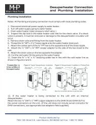
Page 8ENGLISH<strong>Jandy</strong> ® <strong>Pro</strong> <strong>Series</strong> <strong>JE</strong> Heat Pumps | Installation and <strong>Operation</strong> <strong>Manual</strong>To install the anchor clamps:1. Be sure that the heat pump is in its permanentlocation on the equipment pad.2. Place the clamps at the base of the heat pump inthe locations indicated in Figure 2.3. Fit the hook of each clamp over the lip on thebase panel of the heat pump. The hook shouldfit between the lip of the base panel and theevaporator coil guard (see Figure 3).4. Mark the position of the hole in each clamp on theequipment pad.5. Drill a hole in the cement using a masonry drillbit, with a diameter as determined by the concreteanchor, at each of the marks on the equipment pad.The hole should be approximately 1-3/4” deep.6. Insert a bolt anchor into each of the holes. Be surethe anchors are set <strong>com</strong>pletely into the holes.7. Position the anchor clamps so that the holes in theclamps are over the bolt anchors. Be sure that theclamp hooks are over the lip of the heat pump base(see Figure 3).8. Insert an anchor bolt through each clamp into theanchor and tighten to secure the clamp and heatpump to the equipment pad.Section 3. Water Connections3.1 Plumbing LayoutFigure 4 illustrates the standard plumbing layout with asingle heat pump unit. Following the diagram from rightto left, the plumbing sequence is as follows:Pool > Pool Pump > Filter > Heat Pump > CheckValve > Chemical Loop > Chlorinator > PoolNote For normal installations, do not install a shutoffvalve or any kind of variable restriction in thewater piping between the heat pump outlet andthe pool/spa.Arrangement of pool system <strong>com</strong>ponents other thanas illustrated in the preceding and following diagramscan affect the operation of the heat pump’s waterpressure switch. Location of the heat pump above orbelow the pool water surface can also affect operationof the switch. In general, the pressure switch can beadjusted to ac<strong>com</strong>modate this effect if the heat pumpwater connections are no more than 10 feet below thepool water surface or no more than 5 feet above it. Seeinstructions for pressure switch adjustment (Section5.6) in the heat pump start-up section of this manual formore information. If the heat pump is installed outsideof this range, an external flow switch may need to beinstalled in the plumbing upstream of the heat pump.Call the Zodiac technical support department at(800) 822-7933 for details.Be advised that when pool equipment is locatedbelow the pool surface a leak can result in large scalewater loss or flooding. Zodiac cannot be responsiblefor such water loss or flooding or the damage causedby either occurrence.3.2 Water Connections at Heat PumpShipping plugs have been installed in the water inletand outlet ports of the heat pump at the factory.Before installing any plumbing, remove the shippingplugs. Filtered water is plumbed to the inlet, located onthe right side of the heat pump front panel. Heated waterflows through the outlet, located on the left side of theheat pump front. Two inch unions are provided.Plastic piping (PVC Schedule 40) should be connectedto the heat pump. The unions, provided with the unit,accept 2” PVC pipe.CAUTIONMake sure that flow requirements and poolwater turn over rates can be maintained withthe installation of additional heat pumps andplumbing restrictions.3.3 Check Valve InstallationWARNINGA check valve can interfere with the properoperation of certain Suction Vacuum ReleaseSystem (SVRS) products. To avoid possibleentrapment hazard, serious injury, or death,make sure to review the operation/ownersmanual of your particular SVRS productbefore installing the check valve.The heat pump must be protected from back-siphoningof water. If there is any chance of back-siphoning,provide a check valve between the pool and the filterpump inlet.When an automatic chemical feeder is installed in theplumbing, it must be installed downstream of the heatpump. A check valve must be installed between theheat pump and the chemical feeder to prevent backsiphoningof chemically saturated water into the heat
Page 10ENGLISH<strong>Jandy</strong> ® <strong>Pro</strong> <strong>Series</strong> <strong>JE</strong> Heat Pumps | Installation and <strong>Operation</strong> <strong>Manual</strong>4.2 Main PowerElectrical wiring to the heat pump must be inaccordance with the latest edition of the NationalElectric Code ® (NEC ® ), ANSI/National Fire <strong>Pro</strong>tectionAssociation (NFPA 70 ® ) in the United States, and inCanada, the Canadian Electrical Code (CSA ® C22.1),unless local code requirements indicate otherwise.The heat pumps <strong>com</strong>e factory-wired intended for usewith either 230 VAC, 60 Hz single phase or 3 phasefield electrical supply depending on the model. See therating plate for the electrical specifications. All wiringmust be done by a certified electrician.The following is the procedure to wire the <strong>Jandy</strong> <strong>Pro</strong><strong>Series</strong> <strong>JE</strong> heat pump to the electrical source specified onthe Rating Plate:1. Be sure the power to the circuit for the heat pumpis turned off.2. Remove the five (5) screws that attach the service/access panel to the heat pump unit (see Figure 10).3. Remove the front cover of the junction box.4. Electrical supply lines must be run throughwatertight conduit. Route the wires and conduitthrough the knock-out designated for high voltageon the right side of the heat pump. Connect to thebottom of the sheet metal junction box. See Figure10 for knock-out location.5. Connect the wires to the terminals on the maincontactor as shown in the wiring diagrams. Referto Figures 8 and 9.6. Connect the ground wire to the ground lugprovided in the electrical <strong>com</strong>partment.7. Replace the cover of the junction box.8. Replace the service access panel and replace thescrews to hold it in place.9. Connect a copper bonding wire (8 AWG). (InCanada, it shall be not smaller than 6 AWG(13.3 mm 2 ) to the bonding lug on the right side ofthe heat pump.WARNINGELECTRICAL SHOCK HAZARD. This heatpump contains wiring that carries high voltage.Contact with these wires may result in severeinjury or death. Disconnect power circuit beforeconnecting the heat pumpCAUTIONLabel all wires prior to disconnection whenservicing controls. Wiring errors can causeimproper and dangerous operation. Verify properoperation after servicing.
Page 12ENGLISH<strong>Jandy</strong> ® <strong>Pro</strong> <strong>Series</strong> <strong>JE</strong> Heat Pumps | Installation and <strong>Operation</strong> <strong>Manual</strong>2” PVC3” PVCOptionalIsolation ValvesFrom Filter<strong>Manual</strong> Bypass ValveTo PoolFigure 6.Two (2) Heat Pump Plumbing Layout2” PVCOptionalIsolation ValvesFrom Filter3” PVCTo Pool<strong>Manual</strong> Bypass ValveFigure 7.Four (4) Heat Pump Plumbing Layout
<strong>Jandy</strong> ® <strong>Pro</strong> <strong>Series</strong> <strong>JE</strong> Heat Pumps | Installation and <strong>Operation</strong> <strong>Manual</strong>ENGLISHPage 13L2L1WATERDEFROSTTEMP DEFROSTTEMPHIGH REFRIGERANTPRESS SWITCHLOW REFRIGERANTPRESS SWITCHWPOWERINTERFACEBRFAN RELAYRYBKBLBKBRWBLYBKW24 VACTRANSFORMERBKRBLWYYBKBKRBKWCONTACTORYYWRBKRHARD STARTCAPACITOR(OPTIONAL)FANCAPACITORRRWREVERSING VALVE(OPTIONAL)W<strong>JE</strong> 3000TR & <strong>JE</strong>3000TR3 ONLYFACTORY INSTALLED 208/230 VACCOMPRESSORFIELD INSTALLED 208/230 VACFACTORY 24 VAC HARNESSGRFACTORY OPTIONAL 24 VACFACTORY OPTIONAL 208/230 VACR BK BLFAN MOTORBRGRBR/WBK WBLBKCOMPRESSORCAPACITORRBKWATER PRESSURESWITCHGROUND<strong>JE</strong> SERIES230 VACSINGLE PHASE60 HzWIRING DIAGRAMFigure 8.<strong>JE</strong> Single-Phase Electrical Supply Wiring Diagram
Page 14ENGLISH<strong>Jandy</strong> ® <strong>Pro</strong> <strong>Series</strong> <strong>JE</strong> Heat Pumps | Installation and <strong>Operation</strong> <strong>Manual</strong>WATERTEMPHIGH REFRIGERANTPRESSURE SWITCHLOW REFRIGERANTPRESSURE SWITCHL3L2L1USER INTERFACEBLBLDEFROSTTEMPSENSORYYPOWER BOARD COMPRESSORBKBRWBLYW WBKRBLR BL BKBKRBKFANRELAYBKYWBLY BKYYRRYWBKWBLWRBLBKFAN CAPACITORCONTACTORBKGROUNDREVERSINGVALVE(OPTIONAL)WWWATER PRESSURESWITCH<strong>JE</strong> 3000TR & <strong>JE</strong>3000TR3 ONLYFACTORY INSTALLED 208/230 VACFIELD INSTALLED 208/230 VACFACTORY 24 VAC HARNESSFACTORY OPTIONAL 24 VACGRFAN MOTORGR/YBRBR/WWBK<strong>JE</strong> SERIES230 VACTHREE PHASE60 HzWIRING DIAGRAMFigure 9.<strong>Jandy</strong> <strong>Pro</strong> <strong>Series</strong> <strong>JE</strong> 3-Phase Electrical Supply Wiring Diagram
<strong>Jandy</strong> ® <strong>Pro</strong> <strong>Series</strong> <strong>JE</strong> Heat Pumps | Installation and <strong>Operation</strong> <strong>Manual</strong>ENGLISHPage 15SERVICE ACCESSPANEL (5 SCREWS)CONNECTOR FORHIGH VOLTAGE WIRESCONNECTOR FORLOW VOLTAGE WIRESFigure 10. <strong>Jandy</strong> <strong>Pro</strong> <strong>Series</strong> <strong>JE</strong> Heat Pump Front View4.3 BondingCAUTIONThis heater must be connected to a bondinggrid with a solid copper wire not smaller indiameter than 8 AWG (In Canada, it shall be nosmaller than 6 AWG.)The National Electrical Code ® and most other U.S.codes require that all metallic <strong>com</strong>ponents of a poolstructure, including reinforcing steel, metal fittings,and above ground equipment be bonded together witha solid copper conductor not smaller than 8 AWG. Theheat pump, along with pumps and other pool equipmentmust be connected to this bonding grid. A bonding lugis provided on the right hand side of the heat pump toensure this requirement is met.4.4 Optional Remote ControlsElectrical wiring must be in accordance with allapplicable national and local codes and ordinances.Connection to a Remote Pool-Off-Spa Selector(3-Wire Connection)Install the Remote Pool-Off-Spa Selector1. Turn off the power to both the pool/spa controlsystem and the heat pump unit.2. Remove the screws that attach the service/accesspanel to the heat pump unit and the cover to thejunction box (see Figure 10).3. Run the wires from the pool/spa control systeminto the conduit connection labeled “Low VoltageConnection”, located on the lower right hand sideof the heat pump (see Figure 10).4. Connect the wiring from the pool/spa controlsystem to the heat pump remote control terminal(see Figure 11a).5. Restore power to the heat pump and the pool/spacontrol system.Configure the Control Panel1. Make sure the control is in the OFF mode.2. To enter the Service Setup mode, press and holdthe MENU, POOL, and SPA buttons for 5seconds.NOTE The display will revert back to OFF after oneminute since the last key press.3. Press the Up or Down button to displayREMOTE. Press the MENU button. TheSELECT REMOTE OFF (default remote)appears, use the Up or Down button to scrollthrough the Remote options. When you reach HI-LO-COM, press the MENU button to select theremote. Press POOL or SPA to exit the ServiceSetup mode.
Page 16ENGLISH<strong>Jandy</strong> ® <strong>Pro</strong> <strong>Series</strong> <strong>JE</strong> Heat Pumps | Installation and <strong>Operation</strong> <strong>Manual</strong>Two-Wire Connection to an AquaLink ® RSor TSTATConfigure the AquaLink RS ControlSystem1. Turn off the power to both the pool/spa controlsystem and the heat pump unit.2. Connect two (2) wires to the AquaLink RS green10-pin terminals 1 and 2.3. Put DIP S2-1 (pin #1 of the 4 position DIP switch)into the ON position (see Figure 12).Install the Remote TSTAT1. Turn off the power to both the pool/spa controlsystem and the heat pump unit.2. Remove the screws that attach the service/accesspanel to the heat pump unit and the cover to thejunction box (See Figure 10).3. Run the wires from the pool/spa control systeminto the conduit connection labeled “low voltageconnection”, located on the lower right hand sideof the heat pump (See Figure 10).4. Connect the wiring from the pool/spa controlsystem to the heat pump remote control terminal(See Figure 11b).5. Restore power to the heat pump and the pool/spacontrol system.Configure the Control Panel1. Make sure the control is in the OFF mode.2. To enter the Service Setup mode, press and holdthe MENU, POOL, and SPA buttons for 5seconds.3. Press the Up or Down button to displayREMOTE. The SELECT REMOTE OFF(default remote) appears, use the Up or Downbutton to scroll through the Remote options. Whenyou reach REMOTE TSTAT, press the MENUbutton to select the remote. Press POOL or SPAto exit the Service Setup mode.4. Press SPA. For heating, adjust the setpoint to themaximum setting. For chilling, adjust the setpointto the minimum setting.RS485 (4 wire) Connection to AquaLink ® RS1. Confirm the <strong>Jandy</strong> <strong>Pro</strong> <strong>Series</strong> <strong>JE</strong> heat pump andAquaLink RS software revisions are <strong>com</strong>patible.<strong>Jandy</strong> <strong>Pro</strong> <strong>Series</strong> <strong>JE</strong> HeatPump Power InterfaceSoftware Rev.3.0 or Later N or LaterAquaLink ® RS SoftwareRevisionNOTE Only a revision “N”, or higher, program chip inthe RS system will support the <strong>Jandy</strong> <strong>Pro</strong> <strong>Series</strong><strong>JE</strong> heat pump interface.2. Turn off the power to both the heat pump andthe RS control and open the RS Power Centerenclosure and remove the front dead panel.3. Remove the two (2) screws holding the bezel inplace and turn the bezel over to view the circuitboard on the back.4. Locate the programmed chip on the Power CenterBoard. In the center of the chip is the revisionletter. If the revision letter is “N” or higher go tostep 5. If the revision level is “MMM” or lower,replace the board or connect as shown in Section4.5NOTE The display will revert back to OFF after oneminute since the last key press.Figure 11a.remote Pool-Off-Spa Connection(3-Wire Connection)Figure 11b.aquaLink RS or Remote TSTATConnection (2-Wire Connection)
Thu January, 2009 3:03 PMFILTER SPA POOL SPA AUX1 AUX2 AUX3 OtherPUMPHEAT HEATDevicesOn/OffHome Menu OneTouch Help Back Status Photos Power<strong>Jandy</strong> ® <strong>Pro</strong> <strong>Series</strong> <strong>JE</strong> Heat Pumps | Installation and <strong>Operation</strong> <strong>Manual</strong>5. Use 22 gauge 4-conductor wire (Zodiac ® Part No.4278) to run between the heat pump and the RScontrol, and match the wire color order.6. The wires <strong>com</strong>ing from the <strong>Jandy</strong> <strong>Pro</strong> <strong>Series</strong> <strong>JE</strong>heat pump can be “doubled up” on the red terminalbar with the four (4) wires <strong>com</strong>ing from the indoorcontroller.NOTE If you need to install more than two (2) wires ineach terminal, order a Zodiac ® Multiplex PCBKit, which includes the Multiplex Board (ZodiacPart No. 6584). Never put more than two (2)wires into each of the pins of the terminal bar.7. Check all wiring, then apply power to both theheat pump and the RS control system. <strong>Operation</strong>can be verified in either Service or Auto mode. Seethe RS Control System manual for instructionsabout operation.When the <strong>Jandy</strong> <strong>Pro</strong> <strong>Series</strong> <strong>JE</strong> heat pump is firstpowered and there is an RS control connected to theheat pump, the display on the heat pump will show“JANDY REMOTE ONLINE PUSH MENU TODISABLE”. When the <strong>JE</strong> heat pump is online withthe RS control, all functionality of the control on theheat pump is disabled. The heat pump functions can becontrolled only at the RS unit.To temporarily use the heat pump controls, pressthe MENU button. The message “JANDY REMOTEONLINE PUSH MENU TO DISABLE” will disappearfrom the heat pump display. All functionality has nowbeen returned to the control on the heat pump. In thismode the RS unit is no longer controlling the heatpump.ENGLISHPage 17To return the functionality to the RS unit, cycle (turn offand then turn on) the power to the heat pump, or pressthe MENU button for 5 seconds to enter the User SetupMode and then enable the Zodiac Remote.Note If connecting more than two (2) items to the RSPower Center red, 4-pin connector, a MultiplexPCB is required.Connection to a Secondary User Interface1. Turn off the power to the heat pump.2. Remove the five (5) screws that attach the frontpanel to the heat pump and remove the cover tothe junction box. See Figure 10.3. Run four (4) 22 AWG solid copper wires into theconduit labeled “Low Voltage Connection” locatedon the lower right hand side of the heat pump. SeeFigure 10. The wires may be up to 300 feet(91.4 m) in length.4. Connect the wires to the 4 position terminal onthe upper left hand corner of the Power InterfacePC Board, labeled “User Interface1”. The wireswill be added to the existing wiring to the UserInterface installed on the heat pump.5. Ensure the wiring is consistent when connectingthe wires to the second User Interface. Forexample, BK goes to BK, O goes to O, etc.6. Re-install the junction box cover and serviceaccess panel and restore power to the heat pump.AquaLink TouchPool Temp86ºAir Temp78ºHeat PumpConnector for LowVoltage WiresGreen - EnabledRed - OnGreen - EnabledRed - OnHeat Pump ConnectionsTerminals 1 and 2S11 2 3 4 5 6 7 8 1 2 3 4OFF ONOFFS2ONS1S2DIP SwitchesS1 and S24 3 2 1 4 3 2 1RESETAUTOSERVICETIME OUTFILTER PUMPAUX 16 5 4 3 2 1 10 9 8 7 6 5 4 3 2 1AUX 2AUX 3AUX 4RS6 & RS8 ONLYRS8 ONLYAUX 5AUX 6AUX 7HEATER SOLARPOOL MODESPA MODESPA DRAINSPA FILLFigure 12. AquaLink RS to <strong>Jandy</strong> <strong>Pro</strong> <strong>Series</strong> <strong>JE</strong> Heat Pump - T-Stat (2 wire) connection
FILTERPUMPSPAPOOLHEATSPAHEATThu January, 2009 3:03 PMAUX1 AUX2 AUX3 OtherDevicesOn/OffHome Menu OneTouch Help Back Status Photos PowerJANDY AquaLink RS06/26/04 MON6:00 PMFILTER PUMP OFFAIR 79°EQUIPMENT ON/OFFONETOUCH ON/OFFMENU / HELPS1S24 3 2 1 4 3 2 1RESETAUTOSERVICETIME OUTAUX 16 5 4 3 2 1 10 9 8 7 6 5 4 3 2 1AUX 2AUX 3AUX 4RS6 & RS8 ONLYAUX 5AUX 6RS8 ONLYAUX 7HEATERSOLARPOOL MODESPA MODESPA DRAINSPA FILLPage 18®ORENGLISHSection 5. <strong>Operation</strong>AquaLink TouchPool Temp86ºAir Temp78ºORCAUTIONDo not use this heat pump if any part hasbeen under water. Immediately call a qualifiedservice technician to inspect the heater andreplace any part of the control system whichhas been under water.CAUTIONKeep all objects off the top of the heat pump.Blocking air flow could damage the unit andmay void the warranty.5.1 Initial Start-up PrecautionsBe sure that there is water in the pool and that thesurface level is above the skimmer or other inlet of thepool’s filter system.With any new pool or spa installation, operate the filterpump with the heat pump off long enough to <strong>com</strong>pletelyclean the water. This will remove any installationresidue from the water.Clean the filter at the end of this operation beforestarting the heat pump. When raising the temperatureof a cold pool, program the time clock to run the pumpcontinuously.GRNYEL4 3 2 1<strong>Jandy</strong> ® <strong>Pro</strong> <strong>Series</strong> <strong>JE</strong> Heat Pumps | Installation and <strong>Operation</strong> <strong>Manual</strong>BLKREDFILTER PUMPThis lets the filter system and heat pump operatecontinuously until the water reaches the temperaturesetting on the temperature control. When that happens,the heat pump will automatically shut off, but the filterpump will keep running.5.2 Operating the ControllerYour new <strong>Jandy</strong> <strong>Pro</strong> <strong>Series</strong> <strong>JE</strong> heat pump is controlledby an advanced microprocessor based controller thatprovides a sophisticated yet simple interface to operateyour heat pump for maximum efficiency and enjoymentof your pool. To locate the control buttons, see Figure14.Off ModeWhen the control panel is turned off, the screen displaysHEAT PUMP is OFF pRESS Pool or Spa.Pool Mode - (Normal Heat)To enable the pool mode, press POOL. The associatedleft green LED indicator will light and the unit willdisplay SET:xxx°.Note XXX represents the current temperature settingon the control. The default setting for pooltemperature is 80°F (26°C).You can change the temperature set point by pressingthe Up or Down button. Repeatedly press the Up orDown button until you reach the desired temperature setpoint. After 5 seconds of inactivity, the new set point isstored in memory.When the water temperature falls to 1 degree belowthe temperature setting and after a 5 minute delay, thecontrol will start the heat pump and the associated rightLED will light RED.REDBLKYELGRN4-ConductorWire1 2 3 4<strong>Jandy</strong> <strong>Pro</strong> <strong>Series</strong> <strong>JE</strong> Heat Pump Power InterfaceOPTIONALRS PowerCenterPool Mode - (Optional Maintain Heat)If connected, the Maintain Heat mode allows the heatpump to monitor the temperature of the water 24 hoursa day by turning the pool pump on and sampling thewater temperature.A Maintain Temp Relay is required and the feature mustbe enabled.When the water temperature drops below theprogrammed temperature set point, the control will startthe heat pump.To operate in pool mode with the Maintain Heat feature,press POOL, then press MENU, press the Down buttonuntil MAINTAIN POOL HEAT is displayed, press theMENU button.The associated left green LED indicator will light andthe unit will display SET:xxx°. Change the temperatureset point by pressing the Up or Down button untilthe desired set point is displayed. After 5 seconds ofinactivity, the new set point is stored in memory.Figure 13. <strong>Jandy</strong> <strong>Pro</strong> <strong>Series</strong> <strong>JE</strong> Heat Pump toPower Center - RS485 (4 wire) connection
<strong>Jandy</strong> ® <strong>Pro</strong> <strong>Series</strong> <strong>JE</strong> Heat Pumps | Installation and <strong>Operation</strong> <strong>Manual</strong>Spa Mode - (Normal Heat)To enable the spa mode, press SPA. The associated leftgreen LED indicator will light and the unit will displaySET:xxx°.Note XXX represents the current temperature settingon the control. The default setting for spatemperature is 102°F (38°C).You can change the temperature set point by pressingthe Up or Down button. Repeatedly press the Up orDown button until you reach the desired temperatureset point. After 5 seconds of inactivity, the new set pointis stored in memory. When the water temperature fallsto 1 degree below the temperature setting and after a 5minute delay, the control will start the heat pump andthe associated right LED will light RED.Spa Mode - (Optional Maintain Heat)If connected to an AquaLink, the Maintain Heat modeallows the heat pump to monitor the temperature of thewater 24 hours a day by turning the spa pump on andsampling the water temperature.Note This feature only works when connected toan AquaLink.To operate in spa mode with the Maintain Heat feature,press SPA, then press MENU, press the Down buttonuntil MAINTAIN SPA HEAT is displayed, press theMENU button. The associated left green LED indicatorwill light and the unit will display SET:xxx°. Changethe temperature set point by pressing the Up or Downbutton until the desired set point is displayed. After5 seconds of inactivity, the new set point is stored inmemory.5.3 Operating Features of Hybrid Unitswith Optional ChillerNote The chiller is an optional equipment. Not allunits are provided with chiller.Pool Mode - (Normal Chill)To enable the pool mode, press POOL. The associatedleft green LED indicator will light and the unit willdisplay SET:xxx°.Note XXX represents the current temperature settingon the control. The default setting for pooltemperature is 80°F (26°C).Press the MENU button. Press the Up or Down buttonuntil you reach POOL CHILL, press the MENU button.Note POOL CHILL will not be displayed if the unit isnot provided with chiller.You can change the temperature set point by pressingthe Up or Down button. Repeatedly press the Up orDown button until you reach the desired temperatureENGLISHPage 19set point. After 5 seconds of inactivity, the new set pointis stored in memory. When the water temperature risesto 1 degree above the temperature setting and after a 5minute delay, the control will start the heat pump andthe associated right LED will light GREEN.Pool Mode - (Optional Maintain Chill)If connected, the Maintain Chill option mode allows theunit to monitor the temperature of the water 24 hoursa day by turning the pool pump on and sampling thewater temperature.A Maintain Temp Relay is required (provided) and thefeature must be enabled.When the temperature of the water rises above thedesired temperature setting, the control will then turn onthe unit and the associated right green LED will light.To operate in pool mode with the Maintain Chill feature,press POOL, then press MENU, then press the Downbutton until Maintain Pool Chill is displayed,press the MENU button. The associated left green LEDindicator will light and the unit will display Set:XXX°.Change the temperature set point by pressing the Upor Down button until the desired set point is displayed.After 5 seconds of inactivity, the new set point is storedin memory.Spa Mode - (Optional Maintain Chill)If connected to an AquaLink, the Maintain Chill modeallows the heat pump to monitor the temperature of thewater 24 hours a day by turning the spa pump on andsampling the water temperature.Note This feature only works when connected toan AquaLink.When the water temperature rises above theprogrammed temperature set point, the control will startthe heat pump.To operate in the spa mode with the Maintain Chillfeature, press SPA, then press MENU, press the Downbutton until Maintain spa Chill is displayed,press the MENU button. The associated left green LEDindicator will light and the unit will display Set:XXX°.Change the temperature set point by pressing the Upor Down button until the desired set point is reached.After 5 seconds of inactivity, the new set point is storedin memory.
Page 20ENGLISH<strong>Jandy</strong> ® <strong>Pro</strong> <strong>Series</strong> <strong>JE</strong> Heat Pumps | Installation and <strong>Operation</strong> <strong>Manual</strong>5.4 User Setup OptionsThe User Setup options allow the user to select specificLanguages, Temperature Scale, Spa Timer, and DisplayLight options.Language Setup1. Make sure the control is in the OFF mode.2. To enter the User Setup mode, press and hold theMENU button for 5 seconds.NOTE The display will revert back to OFF after oneminute since the last key press.3. To select a language, use the Up or Down buttonto display SELECT USER SETUP LANGUAGE.Press the MENU button. The SELECTLANGUAGE ENGLISH (default language)appears, use the Up or Down button to scrollthrough the language options. When you reach thedesired language, press the MENU button to selectthe language. Press POOL or SPA to exit theUser Setup mode.Temperature Scale Setup1. Make sure the control is in the OFF mode.2. To enter the User Setup mode, press and hold theMENU button for 5 seconds.3. To select temperature scale, use the Up or Downbutton to scroll through to display SELECTUSER SETUP TEMPERATURE SCALE. Pressthe MENU button. The SELECT TEMP SCALE°F (default temperature scale) appears, use theUp or Down button to scroll through the scaleoptions. When you reach the desired temperaturescale, press the MENU button to select. PressPOOL or SPA to exit the User Setup mode.Spa Timer Setup1. Make sure the control is in the OFF mode.2. To enter the User Setup mode, press and hold theMENU button for 5 seconds.3. To select spa timer, use the Up or Down button toscroll through to display SELECT USER SETUPSPA TIMER. Press the MENU button. TheSELECT SPA TIMER CONTINUOUS (defaultspa timer setting) is displayed. To turn the spaon or off indefinitely, press the MENU button toselect.To select the length of time for the spa to run,use the Up or Down button to scroll to displaySELECT SPA TIMER TIME SELECTION. Pressthe MENU button to select. The display SELECTSPA TIME 01:00 HRS (default time setting) isdisplayed. Use the Up or Down button to selectthe length of time for the spa to run (between00:15 to 23:00 hours incremented by 00:15minutes). Press the MENU button to select howlong the spa will run. Press POOL or SPA to exitthe User Setup mode.Display Light Setup1. Make sure the control is in the OFF mode.2. To enter the User Setup mode, press and hold theMENU button for 5 seconds.3. To select display light setup, use the Up or Downbutton to scroll through to display SELECTUSER SETUP DISPLAY LIGHT. Press theMENU button. The SELECT DISPLAY LIGHT2 MIN TIMEOUT (default display light setting) isdisplayed. This option allows the display light toturn off after 2 minutes. Press the MENU buttonto select. Use the Up or Down button to scrollto display SELECT DISPLAY LIGHT LIGHTOFF, this option allows the display light to turnoff, press the MENU button to select. Use theUp or Down button to scroll to display SELECTDISPLAY LIGHT LIGHT ON, this option allowsthe display light to turn on, press the MENUbutton to select. Press POOL or SPA to exit theUser Setup mode.Figure 14. Main Control Panel
<strong>Jandy</strong> ® <strong>Pro</strong> <strong>Series</strong> <strong>JE</strong> Heat Pumps | Installation and <strong>Operation</strong> <strong>Manual</strong>ENGLISHPage 215.5 Set Point LockoutMake sure the control is in the ON mode (POOL orSPA), press and hold the Up and Down buttons for 5seconds. The set point will be locked and the controlwill operate in the mode it was in when the Set PointLockout occurred. If an attempt to change the set pointis made while the control is in Set Point Lockout, thecontrol will display SET POINT LOCKED. To unlockthe Set Point Lockout, press and hold the Up and Downbuttons for 5 seconds. The unit will display SET POINTUNLOCKED.5.6 Water Pressure Switch AdjustmentCAUTIONThe water pressure switch should be adjustedto turn the heater off when the pump is off.Setting the switch to close at too low of a flowcan damage the appliance. Adjust the switchto turn the heater off, not on.The pressure switch is preset at the factory foractivation at 2 psi (14 kPa). This is the minimum settingfor the water pressure switch and works for all basicinstallations. Only adjust the water pressure switch ifthe heat pump does not operate when the proper flowis applied to unit or if the heat pump does not shutoff when the filter pump is off. Occasionally, unusualplumbing configurations or necessary restrictions inthe plumbing may cause pressure sensing problems. Inthese rare situations, the plumbing system configurationmay require adjustment of the water pressure switch.Adjustment of the pressure switch may be necessaryif any part of the filter system piping is 3 feet (1 m) ormore above the top of the heat pump jacket.Do not adjust the pressure switch if the heat pump isinstalled more than 5 feet (1.5 m) above or 10 feet(3 m) below the pool surface. Consult your localZodiac ® dealer for re<strong>com</strong>mendations.On some installations, the piping from the heat pumpto the pool is very short. The back pressure could betoo low to trigger the pressure switch. If this happens,it may be necessary to install a directional fitting orelbows where the return line enters the pool. This willincrease back pressure enough for the heat pump tooperate properly. If this configuration is necessary,be sure to check that the system flow is above theminimum requirement of 30 gpm (114 lpm) after thedirection fitting or elbow has been installed.Make sure the pool filter is clean before making anypressure switch adjustment: A dirty filter will restrict thewater flow and the pressure switch cannot be adjustedproperly.To adjust the pressure switch:1. Be sure that all valves in the system are set toallow water flow through the heat pump. Start thefilter pump.2. Set the heat pump control to call for heat. Set theheat pump control to the POOL HEAT mode.3. If the heat pump control displays “NO FLOW”,then the flow in the system may be below theminimum flow of 30 gpm (114 lpm) needed forthe safe operation of the heat pump. Investigateand correct any flow problems before adjusting thewater pressure switch.4. Remove the heat pump’s control access panel. Thewater pressure switch is located in the lower leftcorner of the control <strong>com</strong>partment.5. After confirming the flow rate is at a minimumof 30 gpm (114 lpm), slowly rotate the thumbwheel on the water pressure switch in acounterclockwise direction until the “NO FLOW”indicator disappears from the control display.Remember that there is a time delay before theheat pump <strong>com</strong>pressor will start.6. Once the heat pump is running, turn off the filterpump. The heat pump should turn off immediately.7. If the heat pump continues to operate when thefilter pump is off, turn the thumb wheel on thewater pressure switch in a clockwise directionuntil “NO FLOW” is displayed on the control andthe heat pump shuts down.8. Check the setting of the water pressure switch bystarting and stopping the filter pump and checkingthe control display and operation of the heaterbetween each flow change.9. If the water pressure switch cannot be adjustedto ac<strong>com</strong>modate the conditions listed above,an external flow switch must be added to theplumbing system to ensure that the heat pump willnot operate without the proper flow through theheat exchanger.Section 6. General Maintenance6.1 Water Chemistry<strong>Pro</strong>per chemical balances are necessary for sanitarybathing conditions as well as ensuring your heat pump’slong life. Be sure to keep your chemical and mineralconcentration levels within the values indicated inTable 3.Note For spas, it is also necessary to perform waterchanges in addition to chemical treatment. It isre<strong>com</strong>mended to change the spa water every60 days for light usage and every 30 days ifusage is heavy.6.2 WinterizingCAUTIONFailure to winterize could cause damage to theheat pump and will void the warranty.In areas where freezing temperatures occur, you shouldprotect your pump, filter, and heat pump from the ele-
Page 22ENGLISH<strong>Jandy</strong> ® <strong>Pro</strong> <strong>Series</strong> <strong>JE</strong> Heat Pumps | Installation and <strong>Operation</strong> <strong>Manual</strong>ments. Perform the following steps to <strong>com</strong>pletely drainthe heat pump (see Figure 15).1. Turn off the electrical power to the heat pump atthe main breaker panel.2. Shut off the water supply to the heat pump.3. Disconnect the water inlet and outlet unions aswell as the winterizing drain plug (if applicable)located on the lower front panel of the heat pump.The heat exchanger will drain through these waterconnections.4. Cover only the top of the heat pump to preventdebris from falling into the unit. Do not wrap thesides of the heat pump with any plastic or othermaterial that will retain heat or moisture insidethe unit.6.3 Spring Start-UpIf your heat pump has been winterized, perform thefollowing steps when starting the system in the Spring:1. Uncover the heat pump and inspect the top andsides for any debris or structural problems.2. Connect the water inlet and outlet unions locatedon the lower front panel of the heat pump.3. Turn on the filter pump to supply water to theheat pump. Circulate water through the systemlong enough to cycle all of the pool water throughthe filter. Check for leaks in and around the heatpump.4. Check the pool chemistry and balance asnecessary.5. Turn on the electrical power to the heat pump atthe main breaker panel.6.4 Inspection and ServiceZodiac ® heat pumps are designed and constructedto provide long performance life when installed andoperated properly under normal conditions. Periodicinspections are important to keep your heat pumprunning safely and efficiently through the years.Owner InspectionCAUTIONDo not use this heat pump if any part has beenunder water. Immediately call a qualified servicetechnician to inspect the heater and replace anypart of the control system which has been underwater.Figure 15. Winterizing the <strong>JE</strong> Heat PumpZodiac re<strong>com</strong>mends that you inspect your heat pumpon a regular basis and especially after abnormal weatherconditions. The following basic guidelines are suggestedfor your inspection:1. Keep the top and surrounding areas of the heatpump clear of all debris.2. Keep all plants and shrubs trimmed and away fromthe heat pump.The heat pump will produce condensation (water) whilein operation. The heat pump base is designed to allowthe condensation to exit through the bottom drain portwhen the unit is running. The condensation will increaseas the outdoor air humidity level increases. Checkthe following at regular intervals to ensure propercondensate drainage:1. Visually inspect and clear the bottom drain portsof any debris that could clog the ports.2. Ensure that condensate water does not puddleinside the heat pump3. Ensure that condensate run-off is properly directedaway from the equipment pad to keep it fromundermining the pad.During normal operation, the heat pump produces3 to 5 gallons of condensate per hour. If condensatedrainage is above this range during operation or if watercontinues to drain from the base when the heat pumpis not in operation for more than an hour, a leak in theinternal plumbing may have occurred. Call a qualifiedheat pump technician to investigate the problem.Keep the top air flow discharge and air flow intake areaclear of debris so the air flow though the heat pumpis not restricted. The cooler discharge air from the topshould not accumulate and be drawn into the side airintake coils. Keep all plants and shrubs trimmed awayfrom the heat pump.Make sure the front of the unit is accessible for futureservice.Keep lawn sprinkler heads from spraying on the heatpump to prevent corrosion and damage. Use a deflectorif needed.If the unit is installed under a very sharp roof pitch orunder a roof without a gutter, a gutter or diverter shouldbe fitted to prevent excessive water from pouring downinto the unit.<strong>Pro</strong>fessional InspectionInspections performed at least once a year by a qualifiedtechnician are required to maintain your heat pump’ssafe and efficient operation. The following basic safetychecks must be performed.1 Check for loose or broken wires and terminalconnections.2. Verify the pressure switch or flow switchoperation. Turn the heat pump OFF. Disconnectthe power to the pump time clock, or turn thepump time clock to an OFF position. Turn the heatpump back ON. The heat pump must not <strong>com</strong>e on.
<strong>Jandy</strong> ® <strong>Pro</strong> <strong>Series</strong> <strong>JE</strong> Heat Pumps | Installation and <strong>Operation</strong> <strong>Manual</strong>ENGLISHPage 233. Inspect the electrical controls, specifically thefollowing:a. High and Low Limitsb. Pressure Switch or Flow Switchc. Temperature Control4. Inspect the evaporator coil for blockage and cleanas necessary.5. Check for spider webs or debris in the condensatedrain; clean if necessary.6. Conduct a normal operating cycle and observe thatthe unit operates properly.Section 7. <strong>Pro</strong>fessional Maintenanceand Service7.1 Heat Pump DesignThe Zodiac ® heat pump is one of the most efficientways to heat a pool or spa. The heat pump transfers heatfrom the outside air to the pool or spa water by meansof an internal heat exchanger.When the fan is turned on, warm air is drawn throughthe refrigerant charged evaporator, turning the coldliquid refrigerant to a warm gas. The gas then flowsthrough the <strong>com</strong>pressor where it is <strong>com</strong>pressed resultingin a much higher temperature.The hot gas enters the heat exchanger where the waterextracts the heat. The pump pulls in cool pool water,which in turn converts the hot gas back into a liquidrefrigerant and starts the cycle over again.The <strong>JE</strong> heat pump and the EE-Ti heat pump uses arefrigerant called R-410A. It is a non-ozone depletingrefrigerant that is accepted by the EPA. R-410A hashigher operating pressures and cooling capabilities thanR-22, which is the refrigerant used in the AE-Ti heatpump. Therefore, R-410A should NEVER be used inany of the AE-Ti heat pumps.The EPA requires certification to purchase or useR-410A. It is re<strong>com</strong>mended that service personnel betrained in installation, service, brazing, and maintenanceprocedures. They are similar to what the industry hasused for the R-22 system, however, they should beredefined for the higher operating pressures.note The maximum heat output and efficiency ofa heat pump is dependent upon the qualityand performance of the major <strong>com</strong>ponentsused. Equally important are the environmentalconditions (for example, air temperature,humidity, water temperature, and wind).7.2 Heat Pump Components and<strong>Operation</strong>Evaporator - As air passes through the evaporator, therefrigerant in the evaporator absorbs heat from theambient air. The warmer the ambient air and thelarger the surface area of the evaporator the moreheat it can collect.Fan - The heat pump fan produces high volume airflow.Adequate airflow is required to move warm airthrough the large evaporator.Compressor - The <strong>com</strong>pressor <strong>com</strong>presses therefrigerant gas to a higher pressure, increasing thetemperature.Heat Exchanger - As the final step to the heatingprocess, the heat exchanger transfers the heatfrom the hot gas to the water. (Also known as acondenser.)Reversing Valve - (For Hybrid Units with OptionalChiller and Hot Gas Defrost) The reversing valvereverses the flow of the refrigerant, which resultsin transferring cold gas to the water, thus loweringthe temperature.Table 3. Optimal Water Chemistry RangesTestRe<strong>com</strong>mended LevelFree Chlorine orBromine1.0 to 3.0 ppm2.0 to 4.0 ppmpH 7.2 to 7.8 (Ideal ranges being between 7.4 and 7.6)Total Alkalinity (TA)Calcium Hardness (CH)Cyanuric AcidTotal Dissolved Solids (TDS)80 to 120 ppm175 to 400 ppm30 to 50 ppm1000 to 2000 ppm (Excluding dissolved NaCl from SaltChlorine Generator)* Concentration levels taken from “Basic Pool and Spa Technology” published by APSP (Association of Pool andSpa <strong>Pro</strong>fessionals).
Page 24ENGLISH<strong>Jandy</strong> ® <strong>Pro</strong> <strong>Series</strong> <strong>JE</strong> Heat Pumps | Installation and <strong>Operation</strong> <strong>Manual</strong>Section 8. Troubleshooting8.1 Troubleshooting GuideThe following table provides symptoms and solutions for general troubleshouting problems for the heat pump.Table 4. Heat Pump Troubleshouting GuideSYMPTOMHeat pump will not start, no control board display.Heat pump will not start, control board display working.Heat pump runs but does not heat.CORRECTIVE ACTIONBreaker or fuse may be tripped. Reset breaker or check fuse. Ifheat pump still does not run, call for service.Three-phase models only - The phases may bereversed or there may be a loss of phase, call for service.Heat pump may be in delay count down of 5 minutes. Makesure control board thermostat is calling for heater to <strong>com</strong>e on(check setting on thermostat and temperature reading). Makesure heat pump is not in cooling mode.Verify cold air is blowing out the top of the heat pump. If theheat pump has just been installed or if the pool water has beenallowed to cool significantly, it is necessary to run the heatpump continually for 24-48 hours. If the heat pump has been inoperation for some time, increase the circulating pump time, orswitch the control board to Maintain Heat function. If heating aspa, verify no air intake stand pipes are open. If heat pump stilldoes not heat, call for service.Heat pump does not run and control board displays:FAULT-NO FLOWVerify circulating pump is on and all necessary valves are in thecorrect positions. Verify filter and skimmers are clean. Checkwater level in pool. Temporarily turn off all fountains and waterfalls that bypass the heat pump water inlet. If this does notcorrect the problem, call for service.Heat pump does not run and control board display shows:FAULT-HIGH REF PRESSUREHeat pump does not run or short cycles and control boarddisplay shows:FAULT-LOW REF PRESSUREHeat pump leaking water.Verify circulating pump is on and that there are no water flowrestrictions to the heat pump. If the filter pump is a two speedor variable speed pump, switch to a higher speed. Make sureall necessary valves are open or in the proper positions to allowproper water flow to the heat pump. Verify filter and skimmersare clean. Check for water level in the pool. This condition mayalso appear if the heat pump has not been operated for anextended period. To clear the condition, cycle the heat pump,on and off, up to 3 times. If this does not correct the problem,call for service.Check that fan is operating and air is <strong>com</strong>ing out of the top ofthe heat pump, while short cycling. If heat pump does not run atall, call for service.Possible heat exchanger or plumbing leak. Turn the heatpump off, then turn circulating pump off for at least one hourto see if the water leak stops. If the water leak stops, normalcondensation is occurring. If the water leak continues, after theheat pump is shut off for at least one hour, call for service.
<strong>Jandy</strong> ® <strong>Pro</strong> <strong>Series</strong> <strong>JE</strong> Heat Pumps | Installation and <strong>Operation</strong> <strong>Manual</strong>ENGLISHPage 258.2 DiagnosticsIn the event a pressure switch opens or another fault condition occurs, the LCD screen will display the fault until theproblem has been resolved. Please refer to the following table for the list of diagnostic conditions.Table 5. Heat Pump DiagnosticsDIAGNOSTIC CONDITIONDESCRIPTIONFAULT-NO FLOWFAULT-LOW REF PRESSURELow or restricted water flow through the heat pump.The external bypass valve is in the wrong position, or the water flow switchhas malfunctioned. The water flow switch opens creating a fault and theheat pump shuts off.When the ambient temperature is low, the suction pressure can dropsignificantly.This fault will cause the low pressure switch to open and the control willshut off the <strong>com</strong>pressor.FAULT-HIGH REF PRESSUREWhen the head pressure builds too high, the high pressure switch will opencausing the heat pump to shut off immediately.The control will sense this fault condition and shut off the <strong>com</strong>pressor untilthe switch re-closes.FAULT-HIGH WATER TEMPWhen the POOL or SPA water temperature heats to the maximum allowedtemperature or above, there could be safety risks for anyone in the water.The water thermostat will read this temperature and the control will shut offthe heat pump unless it is in CHILLER mode.This feature also remains active when the control calls for heat through aremote thermostat. This is to insure that water temperature does not goto an abnormally high level due to a possible malfunction of the remotesensor.FAULT-SHORTED COIL SENSOR-or-FAULT-OPEN COIL SENSORFAULT-SHORTED WATER SENSOR-or-FAULT-OPEN WATER SENSORIn the event that the coil temperature sensor malfunctions or is notconnected the control will shut off the heat pump.In the event that the water temperature sensor malfunctions or is notconnected the control will shut off the heat pump.
Page 26ENGLISHSection 9. Replacement Parts<strong>Jandy</strong> ® <strong>Pro</strong> <strong>Series</strong> <strong>JE</strong> Heat Pumps | Installation and <strong>Operation</strong> <strong>Manual</strong>9.1 Ordering InformationTo order or purchase parts for the <strong>JE</strong> models of heat pumps, contact your nearest Zodiac dealer or distributor. See theZodiac web site at www.Zodiac.<strong>com</strong> for the nearest service center. If they cannot supply you with what you need,contact Zodiac customer support department, telephone (800) 822-7933.9.2 Zodiac ® <strong>JE</strong> Heat Pumps Parts ListKeyNo. Description Model No.OrderPart No.KeyNo. Description Model No.OrderPart No.1 Fan Grille 1500 R05717001 Fan Grille 2000, 2500, 3000 R05718002 Fan Motor 1500 R05719002 Fan Motor 2000, 2500, 3000 R05720003 Fan Blade 1500 R05721003 Fan Blade 2000, 2500, 3000 R05722004 Fan Top 1500 R05723004 Fan Top 2000, 2500, 3000 R05724005 Evaporator Coil / Guard 1500 R05725005 Evaporator Coil / Guard 2000, 2500 R05726005 Evaporator Coil / Guard 3000 R05727006 Compressor 1500 R05728006 Compressor 2000 R05729006 Compressor 2500 R05730006 Compressor 3000 R05731006 Compressor (3 phase) 2500 R05775006 Compressor (3 phase) 3000 R05776007 Condenser 1500 R05777007 Condenser 2000 R05778007 Condenser 2500 R05779007 Condenser 3000 R05780008 Water Manifold Inlet 1500 R05732008 Water Manifold Inlet 2000, 2500 R05733008 Water Manifold Inlet 3000 R05734009 Water Manifold Outlet 1500 R05735009 Water Manifold Outlet 2000, 2500 R05736009 Water Manifold Outlet 3000 R057370010 Base 1500 R057380010 Base 2000, 2500, 3000 R057390011 Electrical Box Cover w/ Hardware All R057400012 Front Panel 1500 R057430012 Front Panel 2000, 2500 R057440012 Front Panel 3000 R057450013 Water Temperature Sensor All R057460014 Filter Drier 1500 R057470014 Filter Drier 2000, 2500, 3000 R057480014 Filter Drier (Bi-flow) 3000TR R057490015 Thermal Expansion Valve 1500 R057500015 Thermal Expansion Valve 2000, 2500 R057510015 Thermal Expansion Valve 3000 R057520016 Air Temperature Sensor All R057530017 High Pressure Switch All R057540018 Low Pressure Switch All R057550019 Water Pressure Switch All R057560020 User Interface All R300880121 Interface Cover All R300060122 Reversing Valve (optional) 3000TR R057590023 Winterizing Drain Kit 2000, 2500, 3000 R057600024 Power Interface PCB All R300920025 Transformer All R057620026 Run Capacitor (1 phase) 1500 R057630026 Run Capacitor (1 phase) 2000, 2500, 3000 R057640027 Fan Capacitor 1500 R057650027 Fan Capacitor 2000, 2500, 3000 R057660028 Hard Start Capacitor 1500 R057670029 Contactor (1 phase) All (1 Phase) R057680029 Contactor (3 phase), All (3 Phase) R057690030 Fan Relay All R057700031 Phase Rotation Monitor (3 phase) 2500, 3000 (3 Phase) R0577100Optional Components32* Anchor Bracket Set 1500 R057720032* Anchor Bracket Set 2000, 2500, 3000 R057730033 Universal Union, Butress Set All R047270034* Bypass, External, <strong>JE</strong> Heat Pump All R0578900* Not Shown
<strong>Jandy</strong> ® <strong>Pro</strong> <strong>Series</strong> <strong>JE</strong> Heat Pumps | Installation and <strong>Operation</strong> <strong>Manual</strong>9.3 Zodiac ® <strong>JE</strong> 1500 Heat Pumps Exploded ViewENGLISHPage 27121232045C171514181211671619*See Figure 19for detailDETAIL CSCALE 1 : 8 13339810Figure 16. Zodiac <strong>JE</strong> Heat Pumps Exploded View (<strong>JE</strong>1500 Shown)
Page 28ENGLISH<strong>Jandy</strong> ® <strong>Pro</strong> <strong>Series</strong> <strong>JE</strong> Heat Pumps | Installation and <strong>Operation</strong> <strong>Manual</strong>9.4 Zodiac ® <strong>JE</strong> 2000, <strong>JE</strong>2500 & <strong>JE</strong>3000 Heat Pumps Exploded View1221342051522C1461311971918*See Figure 20for detailDETAIL CSCALE 1 : 817123382310Figure 17. Zodiac <strong>JE</strong> Heat Pumps Exploded View (<strong>JE</strong>2000 Shown)
<strong>Jandy</strong> ® <strong>Pro</strong> <strong>Series</strong> <strong>JE</strong> Heat Pumps | Installation and <strong>Operation</strong> <strong>Manual</strong>9.5 Zodiac ® <strong>JE</strong> Single Phase Electric BoxENGLISHPage 2924 2530262928 27<strong>JE</strong>1500 ONLYFigure 18. Zodiac <strong>JE</strong> Single Phase Electric Box199.6 Zodiac ® <strong>JE</strong> Three Phase Electric Box24 312527302919Figure 19. Zodiac <strong>JE</strong> Three Phase Electric Box
Zodiac Pool Systems, Inc.2620 Commerce Way, Vista, CA 920811.800.822.7933 | www.ZodiacPoolSystems.<strong>com</strong>Zodiac Pool Systems Canada, Inc.2115 South Service Road West, Unit 3 Oakville, ON L6L 5W21-888-647-4004 | www.ZodiacPoolSystems.caETL LISTEDCONFORMS TOUL STD 1995CERTIFIED TOCAN/CSA C22.2 NO.236ZODIAC ® is a registered trademark of Zodiac International, S.A.S.U., used under license.All trademarks referenced herein are the property of their respective owners.©2013 Zodiac Pool Systems, Inc. H0408600 Rev C